Casting Foundry or casting is the process of


 • Machine tool")


")


 Moisture Content Test : The moisture Content Test is carried out")
 Permeability Test Inverted bell Jar Air Water Seal Permeability Tester Standard Size rammed")


 Top Gate: ØAlso called drop gate because molten metal just drops on")


 Moulding Machine: - ØConsist of cylinder & piston attached to")


 Pressure Die-Casting Ø")


/ Buckle (Tensile Strength @ Solidify)/ Cold Shut (Two")


- Slides: 65
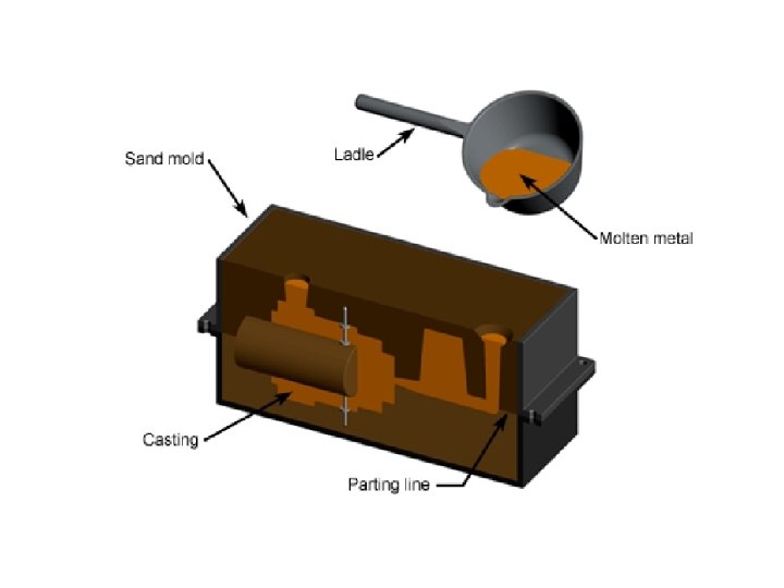
Casting “Foundry or casting is the process of producing metal/alloy component parts of desired shapes by pouring the molten metal/alloy into a prepared mould (of that shape) and then allowing the metal/alloy to cool and solidify. The solidified piece of metal/alloy is known as a CASTING”.
Patterns also have core prints that create registers within the molds into which are placed sand cores Cope & drag (top and bottom halves of a sand mold), with cores in place on the drag
Steps involved in making a casting: 1. Make the pattern out of Wood , Metal or Plastic. 2. Prepare the necessary sand mixtures for mould and core making. 3. Prepare the Mould and necessary Cores. 4. Melt the metal/alloy to be cast. 5. Pour the molten metal/alloy into mould and remove the casting from the mould after the metal solidifies. 6. Clean and finish the casting. 7. Test and inspect the casting. 8. Remove the defects, if any. 9. Relieve the casting stresses by Heat Treatment. 10. Again inspect the casting. 11. The casting is ready for shipping.
Advantages of Metal Casting • Casting is one of the most versatile manufacturing processes. • It provides the greatest freedom of design in terms of shape, size and quality of product. • It provides better vibration damping capacity to the cast components. • Complex and uneconomical shapes which are difficult to produced by other processes can be easily produced by casting process. • A product obtained by the casting is on piece, hence there is no need of metal joining processes. • Very heavy and bulky parts which are difficult to get fabricated, may be cast. • It used for mass production of components.
Applications of Metal Casting • In the Transportation vehicles(in automobile engine) • Machine tool structures. • Turbine vanes and power generators • Pump filters and valves. • Railway crossings and aircraft jet engine blades. • Agricultural parts. • Construction, communication and atomic energy applications, etc.
Pattern Making: • A pattern is a mould forming tool in the hands of foundry men. • A pattern is define as a model or replica of the object to be cast. • A pattern exactly resembles the casting to be made except for the various allowances. • It is the model or form around which sand is packed to give rise to a cavity called as Mould cavity, in which molten metal is poured and the casting is produced. • A pattern may not have holes and slots which a casting will have, such holes and slots make a pattern complicated, hence can be drilled in the casting after it has been made.
Function of Pattern • To prepare the mould cavity of appropriate shape and size for the purpose of making a casting. • To produce seats for the cores in the mould in which the cores can be placed, for producing cavity in the casting, such a seats is called as coreprints. • To minimize casting defects. • It should minimize overall casting cost.
Sand Casting Process
Types of Pattern The most commonly used patterns in foundry are as follows 1) SINGLE PIECE PATTERN 2) SPLIT PATTERN OR TWO PIECE PATTERN 3)MULTIPLE PIECE PATTERN 4) GATED PATTERN 4) COPE AND DRAG PATTERN 5) MATCH PLATE PATTERN 6) LOOSE PIECE PATTERN 7) FOLLOW BOARD PATTERN 8) SWEEP PATTERN 9) SKELETON PATTERN http: //wiki. answers. com/Q/Different_types_of_pattern_used_for_metal_casting#ixzz 1 z. XIhmi. RI http: //books. google. co. in/books? id=4 yj 4 Bgr. YZq. YC&pg=PA 78&lpg=PA 78&dq=follow+board+pattern&source=bl&ots=7 ui 0 Dg 2 JT 8&sig=VCABb. Yx. C z 1 Uk 5 qhzts. Gdu 5 Ky. Wo&hl=en&sa=X&ei=O 8 rz. T 42 HBMj. Mr. Qeuv. Kja. Bg&ved=0 CE 0 Q 6 AEw. BA#v=onepage&q=follow%20 board%20 pattern&f=false http: //books. google. co. in/books? id=l. Ureee. P 2 w. Og. C&pg=RA 1 -PR 1&lpg=RA 1 PR 1&dq=follow+board+pattern&source=bl&ots=CLp. LAWy. Kau&sig=c. Jk. F 9 RK 99 Wz. Jkem. Nkkksjgk. AZng&hl=en&sa=X&ei=O 8 rz. T 42 HBMj. Mr. Qeuv. Kja Bg&ved=0 CEYQ 6 AEw. AQ#v=onepage&q=follow%20 board%20 pattern&f=false
Design Rules INCORRECT Part with thick walls Non-uniform wall thickness (t 1 ≠ t 2) Sharp corner No draft angle CORRECT Part redesigned with thin walls Uniform wall thickness (t 1 = t 2) Rounded corner Draft angle (q)
Solid Pattern:
Allowances §Contraction allowances / Shrinkage allowance §Draft allowance §Finishing or Machining allowance §Shake allowance §Distortion allowance
Types of Sand Used in Sand Casting: Naturally BondedØ Ø less expensive but it includes organic impurities reduce the temperature of the sand for the casting, lower the binding strength require a higher moisture content. Synthetic SandØ Ø Ø mixed in a manufacturing lab starting with a pure (Si. O 2) sand base. composition can be controlled more accurately which imparts the casting sand mixture with higher green strength more permeability, and greater refractory strength. For these reasons synthetic sand is mostly preferred in sand casting manufacture.
Properties of a Sand Casting Mixture Ø Type and Content of binder and other additives (key to controlling the properties) Ø Moisture Content (steam bubbles- affects strength and permeability) Ø Collapsibility (it allow for free shrink during solidification and avoids hot tearing or cracking) Ø Refractory Strength (bear up levels of extreme temperature- mold must not melt, burn, crack, or sinter) Ø Strength (hold its geometric shape) Ø Permeability (permit to escape-air, gases, steam) Ø Thermal Stability ( to avoid breaking, buckling of mould surface at higher temp) Ø Flowability (ability of sand to get compacted to a uniform density) Ø Grain Size (affect the properties of sand) Ø Shape of Grains ( round, sub angular or very angular)
Sand Testing 1) Moisture Content Test : The moisture Content Test is carried out by using Moisture Determining apparatus Consist of : - ØCast Iron Base, ØInfrared heating bulb ØDrying Pan Procedure : - Ø 20 to 40 gm sand sample in pan ØHeated 2 to 3 minutes ØMoisture is evaporated Moisture Determining apparatus ØPan removed & sample is reweighted ØDiff in weights expressed in % of total weight of the sand sample.
2) Permeability Test Inverted bell Jar Air Water Seal Permeability Tester Standard Size rammed Specimen Tube Pressure Manometer It is Property of moulding sand which permits to escape the steam & othergasesgeneratedinthe sand during hot metal pouring Depends on: ØGrain Shape & Size ØWater amount ØGrain Distribution ØDegree of Ramming Procedure: Ø 2000 c. c of air forced to pass through the sand specimen. ØStabilized pressure reading on manometer (Air entering is equal to air escaped through specimen) ØAt same time, the time req. for 2000 cc of air to pass through sand recorded by using stop watch. Permeability No. = V x h / a x p x t Where , V = Volume of air (2000 cc) h = Height of specimen (5. 08 cm) a = Area of specimen (20. 268 cm^2) t = Time for 2000 cc air ( in minutes)
Grain Fineness Test ØDetermines : - grain size, distribution & grain fineness. ØEleven std. sleeve Mounted one above the other on power driven shaker ØPan is placed under the bottom-most sleeve ØThe coarsest sleeve at top & finest at the bottom and remaining placed top to bottom in order of fineness. ØWhole unit is shaken by electric motor. ØSample of dry sand placed in upper most sleeve & vibrated for definite period of time. ØThe amount of sand retained on each sleeve is weighted & find % distribution of sand. AFA Grain fineness No. = Sum of products Total sum of the % of sand retained on pan & each sleeve
Compression Strength Test: - Consist : ØHand wheel ØTwo Indicators of high strength & low strength ØFixed & movable Jaw Working: ØBuild up the hydraulic pressure on specimen ØMeasured deformation occurring in specimen by using dial indicator ØThe first one for testing low strength moulding sand & second for high strength ØSame apparatus is also used for testing tensile strength , shear strength of sand
Cores Horizontal Core : - ØPositioned Horizontally ØAccording to Shape & size ØUniform Cores mostly placed at parting Line Vertical Core : - ØPositioned Vertically ØTapper of core as shown in fig. ØMajor portion generally remains in the drag.
Hanging Core: - ØAlso called as cover core ØSupported from above & Hangs vertically ØNo support from bottom Balanced Core : - ØSupported & balanced from its one end only ØIt req. long core seat to avoid fall into mould cavity.
Kiss Core: - ØDoes not req. core seats for support ØIt is held in position between drag & cope due to pressure exerted by core on the drag Drop Core: - ØAlso called as stop off core ØIt is use to make cavity which can not be made with other
Shell Moulding Ø metal, 2 -piece pattern, 175 C-370 C Ø remove patterns, Ø coated with a lubricant (silicone) Ø join half-shells mold Ø mixture of sand, Ø pour metal Ø cure (baking) Ø solidify (cooling) Ø break shell part
Gating System Ø The method of forming channels in the sand. Ø By means of which molten metal is delivered Diff passage are: - ØPouring cups : - Funnel Shape cup, Easer for crucible operator to direct flow of metal from crucible to sprue. ØPouring basins : - Acts as reservoir , It prevent the mould form dirt, which floats on the top of molten metal. ØSprue : - the channel through which metal is enters in runner & gates, may be square or round, up to 20 mm dia. it is round, where as larger are generally rectangular. ØRunner: - A passage through which molten metal is carried to several gates called as runner, Shape & location ( cope or drag ) is depending upon casting,
Gates : ØChannel which connects runner with the mould cavity, for filling molten metal. ØLocation & size depending upon casting , ØMore than One is employed to feed a fast freezing casting. ØNot having sharp edges to avoid damage ØIngate is the end of the gate where it joins the mould cavity. ØRunner Extension is used to reduce the speed (K. E. energy) molten metal for smoother flow. Gate Ratio = Sprue base area Total runner area + Total ingate area Types : 1) Parting Line Gates ØMould cavity along the parting line ØSimple in construction
2 ) Top Gate: ØAlso called drop gate because molten metal just drops on the sand. ØIt is not favourable 3) Bottom Gate : ØProvided in drag ØMolten metal fills rapidly from bottom ØNot use in large & deep casting because metals cools during pouring. 4) Side Gate : ØProvided either left or right side of casting ØEnters near bottom first, & then other level.
Riser ØAlso called as feeder head. ØA passage of sand permits the molten metal to rise above the highest point. ØAlso permits the air & gas to exit. ØActs as indicator (completely fill or not) Top Riser ØAlso called as dead riser or cold riser. ØLocated at the top of casting. ØMore saving of material as compared to other. Side Riser ØAlso called as Live riser or hot riser. ØFilled at the last & contain hottest metal.
Open Riser : - Blind Riser: - ØOpen to the atmosphere at the top. ØNot open & surrounding by moulding sand ØGenerally cylindrical in shape. ØIt is connect at top or side or parting line. ØAtm. Pressure & the force of gravity till ØIt associate a slow cooling rate. the surface of it solidifies. ØDifficult to mould.
Hand Moulding Equipments Shovel: - ØConsists of an iron pan with wooden handle ØUsed for mixing & conditioning the foundry sand. Rammers : Used for a sand to pack it uniformly around the pattern. Lifter or cleaner : Finishing tool & used for repairing & finishing mould. Used for draw the patterns from mould. Bellow : Used to blow away the loose & unwanted sand.
Hand Moulding Equipments Hand Riddle : - ØConsists of a wooden frame with wire mesh ØUsed for cleaning & removing foreign materials. Slicks: - ØUsed for repairing & finishing the mould surface & edge. ØCommonly used are heart & square, heart & spoon. Draw spike : - ØTapper steel rod having ring at one end & sharp point at other. ØUsed to rap & draw patterns from the mould. Sprue Cutter: - ØHollow taper pipe inserted in sand to produce a hole. Striking off bar: - ØFlat bar made of wood or iron shown in fig ØUsed to remove excess sand from the top of moulding box.
Hand Moulding Equipments Vent wire : - ØA thin steel rod or wire carrying a pointed edge ØCreating a vent to permits a gas to exit. Trowels: - ØAre used for finishing flat surfaces & joints in mould Draw Screws & rapping Plate: - ØUsed for lifting plate form sand ØPlate is provided with several holes shown in fig Mallet: - ØUsed for rapping Gate Cutter: - ØUsed to cut the gate
Hand Moulding Equipments Smoothers & Corner slicks : - ØFinishing tool ØUse for finishing flat & round surfaces Sprue pin : - ØTapper rod of wood or iron ØPlaced & rammed the sand then removed. ØForm a hollow tapper cavity called sprue. Brush & Dust bag : - ØBrush used for sweeping away the mould sand ØDust bag used for parting compound
Moulding Machine Squeeze Moulding Machine: ØVery useful for shallow patterns. ØCompress the sand above & around the pattern by using plate , pressure board. ØSand is rammed harder at mould box & softer at pattern face. ØIn another type of m/c, pressure created by compressed air on rubber diaphragm. ØThe pressure obtained by the rubber diaphragm is higher than a piston type.
Moulding Machine Jolt (Jar) Moulding Machine: - ØConsist of cylinder & piston attached to m/c table. ØMoulding flask fitted with sand allow to drop by gravity. ØFlask rest on table & sudden jolt is caused. ØFalling table is stopped by the solid base of m/c ØInertia of sand causes it to pack with greatest density at deepest portion & top portion, sand packing will be negligible due to less density. ØDepending up on density of sand the desired number jolts are used & pneumatically operated. ØJolting will continue until the valve remains open.
Moulding Machine Jolt- Squeeze Machine : - ØIt overcomes the drawback of both squeeze m/c ØMostly used for match plat moulding. ØSand around pattern is rammed due to jolting action , while upper side is rammed by squeezing action for uniform ramming. ØFor two separate action separate two cylinder & piston are provided whose timings are well adjusted to give the desired effects of jolting & squeezing one after the other.
Moulding Machine Sand Slinger : Ramming Head ØSand rammed by throwing a very high velocity. ØConsist of Impeller or Ramming head ØPicks-up the sand & throws it downwards into the flask. ØRate of discharging of sand is 300 to 2000 kg/minute. ØBucket elevator are used to conveyed the sand up to ramming head. ØMovement is control by swinging arm. Øm/c are mostly used in large foundries.
Casting Processes : - Type of Casting Process : - 1) Pressure Die-Casting Ø Hot Chamber Die-Casting Ø Cold Chamber Die-Casting 2) Centrifugal Casting Ø True Centrifugal Casting Ø Semi- Centrifugal Casting Ø Centrifuging 3) Investment Casting 4) Continues Casting
Casting Processes : Hot Chamber Die-Casting : - ØMolten metal is poured into a metal mould known as Die. ØMetal is forced into the mould & pressure is maintained by a plunger or comp. air. Port ØA port is provided for entry of molten metal. ØIn downward stroke port is closed & applies pressure on metal present in goose-neck. ØTo forced molten metal in to die cavity through the injecting nozzle. ØDies are open & casting is ejected. ØAgain change the die & repeat the cycle. ØGenerally used for low melting point metals. (i. e. Zinc, Tin, Lead. )
Casting Processes : - Advantages Disadvantages ØHigh dimensional accuracy ØHigh initial cost ØFast Production Ølimited to high fluidity metals ØThinner walls are achievable (0. 6 -0. 8 mm) (Zinc, Al, Mg, Cu, Lead and Tin) ØWide range of shapes ØCastings must be smaller ØGood finish
Casting Processes : - Cold Chamber Die-Casting : - ØConsist of separate furnace for melting the metal. ØSeparate melted metal transferred to cold chamber by using small hand ladle. ØTo forced the metal into the die by plunger. ØAfter solidification, the die is opened & casting is ejected. ØLife is more because melting unit is separate. ØUse for aluminum, brass, magnesium.
Casting Processes : Centrifugal Casting : - ØAlso known as liquid forging. ØMould is rotated at high speed & molten metal is poured in it. ØDue to centrifugal force, metal is directed outwards from the centre with high pressure ØUniform thickness of metal is deposited on inner surface. ØCasting is with greater accuracy & better physical properties for symmetrical shapes. Classified as : - Ø True Centrifugal Casting. Ø Semi - Centrifugal Casting. Ø Centrifuging
Casting Processes : True Centrifugal Casting. Ø Axis of rotation of mould & that of the casting are same. Ø No need of central core for producing central hole. Ø Flask is dynamically balanced to reduce vibrations during the process. Ø Molten metal is poured, centrifugal force throws the metal towards outer walls. Ø Outer surface of the mould is water cooled. Ø Used to cast hollow cylindrical objects , i. e. pipes, barrels,
Casting Processes : Semi - Centrifugal Casting : - Ø Molten metal is poured through a central sprue. Ø As the speed of rotation is low, centrifugal force & pouring pressure produced is low. Ø Method is used for produce larger sized symmetrical casting , i. e. pulleys, gears,
Casting Processes : Centrifuging : - Ø Also called as pressure casting. Ø Several casting cavities are located around the outer portion of mould & metal is fed by radial gates. Ø Centrifugal force produces sufficient pressure to force the metal in to cavity. Ø Used for unsymmetrical objects.
Casting Processes : Investment Casting : ØAlso known as lost-wax process. ØAllowed to form a hard layer around pattern. ØMould cavity is obtained by melting wax pattern. Steps : ØDie Making : - Made by using master pattern. ØWax patterns & gating Systems: -wax is injected into the die at 700 c to 800 c at pressure of 8 to 150 kg/cm 2. Assembling : - Gates, Sprues assembles with the help of heated tool known as hot wire welder. It is used to minimize the operation time.
Casting Processes : Precoating : - silica solution is proved for uniform coating Investing : - The whole system is then vibrate & material settles by gravity & mould is then allowed to air-set. Wax melting : - at 2000 c Pouring : - Air pressure may be applied to fill the mould cavity. Cleaning & Inspection : - After solidification gates, riser are then chipped off. Inspected through the specified inspection method.
Casting Processes : -
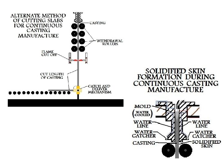
Continuous Casting
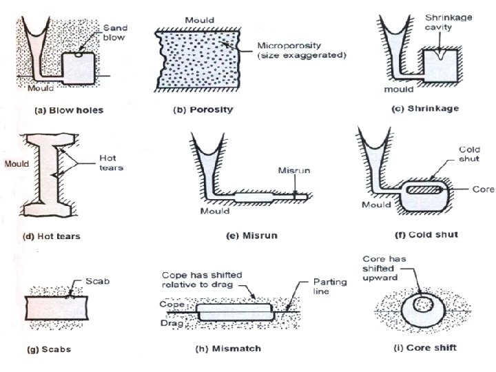
Casting Defects Flash Improper filling-weight down the mold Jt. Flash or Run out Mold Shift/ Mismatch Sand Inclusions Improper alignment Short Casting/ Misrun Porosity/ Metal Penetration
Casting Defects Rat tail (excess part)/ Buckle (Tensile Strength @ Solidify)/ Cold Shut (Two metal fusion) Gas Shrinkage Depression Defect Rough Surface Defect too rough and uneven in surface Crack Defect inside of metal castings Blowhole Defect Hot Tears inadequate compensation of solidification shrinkage by melt flow in the presence of thermal stresses
Casting Inspection & Testing §Visual- Misrun/Cracks §Dimensional Insp. - Tools/ Gauge §Metallurgical Control- Chem. Composition /Mech. Properties §Pressure Testing- Water/air §Radio graphical test (X ray- Gamma Ray )Internal defects/ cracks/voids/cavities §Magnetic Test- Internal defects/ cracks §Ultra sonic Testing-
Sand Casting Methods 1. Green sand 2. Air set method. Green sand • These expendable molds are made of wet sands that are used to make the mold's shape. The name comes from the fact that wet sands are used in the molding process. Green sand is not green in color, but "green" in the sense that it is used in a wet state (akin to green wood). Unlike the name suggests, "green sand" is not a type of sand on its own, but is rather a mixture of: • silica sand (Si. O 2), or chromite sand (Fe. Cr 2 O), or zircon sand (Zr. Si. O 4), 75 to 85%, or olivine, or staurolite, or graphite. • bentonite (clay), 5 to 11% • water, 2 to 4% • inert sludge 3 to 5% • anthracite (0 to 1%) Air set method The air set method uses dry sand bonded with materials other than clay, using a fast curing adhesive Dry-Sand molds are baked in an oven, (at 300 F - 650 F for 8 -48 hours), prior to the casting operation, in order to dry the mold. This drying strengthens the mold, and hardens its internal surfaces. Dry-Sand molds are manufactured using organic binders rather than clay.
Centrifugal casting or rotocasting
Investment casting or lost-wax casting, Valve for Nuclear Power station The investment shell for casting a turbocharger rotor A wax pattern used to create a jet engine turbine blade A view of the interior investment shows the smooth surface finish and high level of detail The completed work-piece
Steps in Investment Castings Process Prepare Patterns by investment casting wax i. e. injected into a metal wax injection die (Fig. 1). Once a wax pattern is produced, it is assembled with other wax components on a central wax stick, called a sprue, to form a casting cluster or assembly or tree (Fig. 2).
The entire wax assembly is then dipped in a ceramic slurry and covered with a sand stucco (refractory material) and allowed to dry. - Fig. 3 (dipping and stuccoing process is repeated until shell of ~6 -8 mm (1/4 -3/8 in) is applied. ) After drying the entire assembly is placed in a steam autoclave to remove most of the wax. The remaining amount of wax soaked into the ceramic shell is burned out in a furnace. Fig. 4 At this point, all of the residual pattern and gating material is removed, and the ceramic mold remains. The mold is then preheated to a specific temp. and filled with molten metal, creating the metal casting (Fig. 5).
Once the casting has cooled sufficiently, the mold shell is chipped away from the casting (Fig. 6). Next, the gates and runners are cut from the casting (Fig. 7). After minor final post processing (sandblasting, machining), the castings - identical to the original wax patterns - are complete and ready for shipment (Fig. 8).
Aluminium Silicon alloy casting ring broken from the mould after room temperature cooling.
Advantages • • Better surface finish Better dimensional tolerances. Reduced Machining. Less foundry space required. Semi skilled operators can handle the process. The process can be mechanized. Disadvantages · The raw materials are relatively expensive. · The process generates noxious fumes which must be removed. · The size and weight range of castings is limited. One major disadvantage is that the gating system must be part of the pattern because the entire mold is formed from the pattern, which can be expensive. Application • Crankshaft fabrication • Steel casting parts, fittings • Moulded tubing fabrication
References Øhttp: //wiki. answers. com/Q/Different_types_of_pattern_used_for_metal _casting#ixzz 1 z. XIhmi. RI Øhttp: //books. google. co. in/books? id=4 yj 4 Bgr. YZq. YC&pg=PA 78&lpg=PA 78 &dq=follow+board+pattern&source=bl&ots=7 ui 0 Dg 2 JT 8&sig=VCABb. Yx. Cz 1 Uk 5 qhzts. Gdu 5 Ky. Wo&hl=en&sa=X&ei=O 8 rz. T 42 HBMj. Mr. Qeuv. Kja. Bg&ved=0 CE 0 Q 6 AEw. BA#v=onepage&q=follow%20 board%20 pattern&f=false Øhttp: //books. google. co. in/books? id=l. Ureee. P 2 w. Og. C&pg=RA 1 PR 1&lpg=RA 1 PR 1&dq=follow+board+pattern&source=bl&ots=CLp. LAWy. Kau&sig=c. Jk. F 9 R K 99 Wz. Jkem. Nkkksjgk. AZng&hl=en&sa=X&ei=O 8 rz. T 42 HBMj. Mr. Qeuv. Kja. Bg&v ed=0 CEYQ 6 AEw. AQ#v=onepage&q=follow%20 board%20 pattern&f=false ØText Book “ Manufacturing Process” Vol. 1, by Hajra Chaudhary ØText Book “ Manufacturing Process” by Bawa