
Chemoreceptive Neuron MOS C MOS Transistors for Environmental

- Slides: 46
Chemoreceptive Neuron MOS (C MOS) Transistors for Environmental Monitoring: Detection in Fluid and Gas Ambients with Field Programmability and High Reliability Edwin C. Kan School of Electrical and Computer Engineering Cornell University RD 83
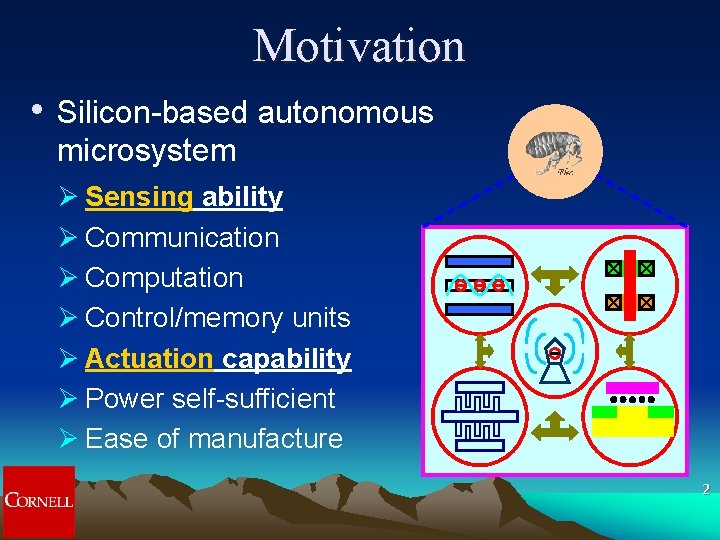
Motivation • Silicon-based autonomous microsystem Ø Sensing ability Ø Communication Ø Computation Ø Control/memory units Ø Actuation capability Ø Power self-sufficient Ø Ease of manufacture 2
Outline • C MOS Overview Ø Why – Review of literature Ø What – C MOS device structure Ø How – Device operation q Sensors q Fluid ambient (Na+, K+ , Ca 2+, BSA and SDS) q Gas ambient (CO 2) q Readout circuits q Actuators Ø Conclusion 3
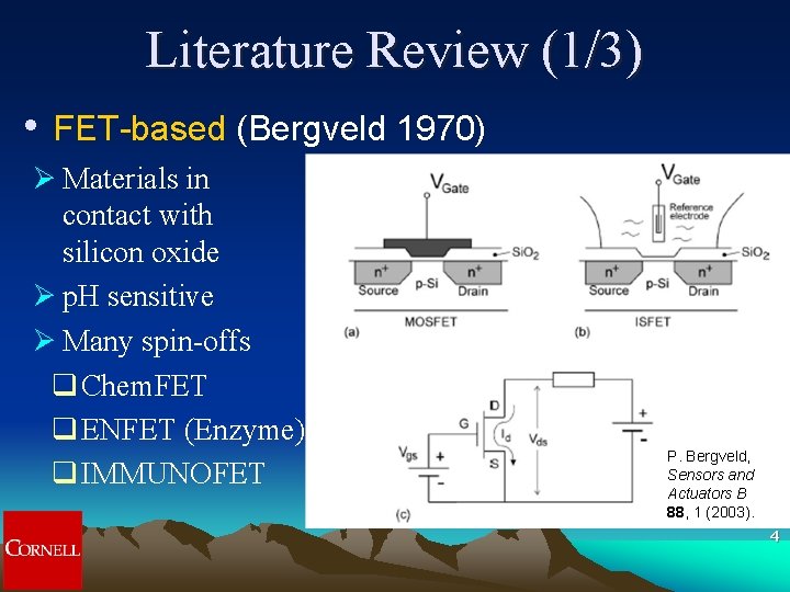
Literature Review (1/3) • FET-based (Bergveld 1970) Ø Materials in contact with silicon oxide Ø p. H sensitive Ø Many spin-offs q Chem. FET q ENFET (Enzyme) q IMMUNOFET P. Bergveld, Sensors and Actuators B 88, 1 (2003). 4
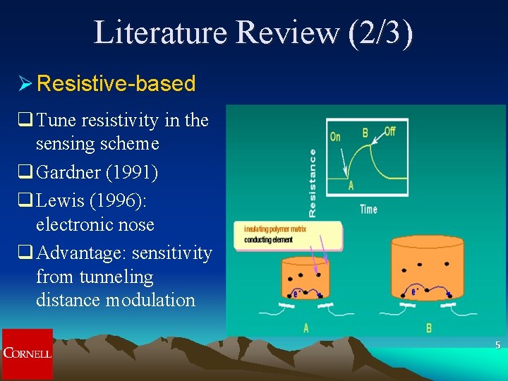
Literature Review (2/3) Ø Resistive-based q Tune resistivity in the sensing scheme q Gardner (1991) q Lewis (1996): electronic nose q Advantage: sensitivity from tunneling distance modulation 5
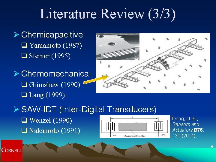
Literature Review (3/3) Ø Chemicapacitive q Yamamoto (1987) q Steiner (1995) Ø Chemomechanical q Grimshaw (1990) q Lang (1999) Ø SAW-IDT (Inter-Digital Transducers) q Wenzel (1990) q Nakamoto (1991) Dong, et al. , Sensors and Actuators B 76, 130 (2001). 6
Why C MOS? • • • Integrated device structure for sensors Enhancement of DOFs in sensing Ease of integration with current CMOS technology Charge-based operation to reduce power consumption Potential for sensor-array application Possibility to integrated sensors and actuators with the same structure 7
C MOS Objectives • • High sensitivity High selectivity Reproducibility, stability and reliability Simple calibration and reset protocols Field reconfigurability Versatile transient measurement Low power consumption in the system Low manufacturing cost 8
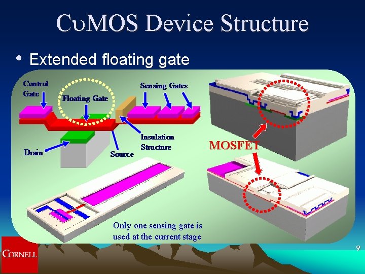
C MOS Device Structure • Extended floating gate MOSFET Only one sensing gate is used at the current stage 9
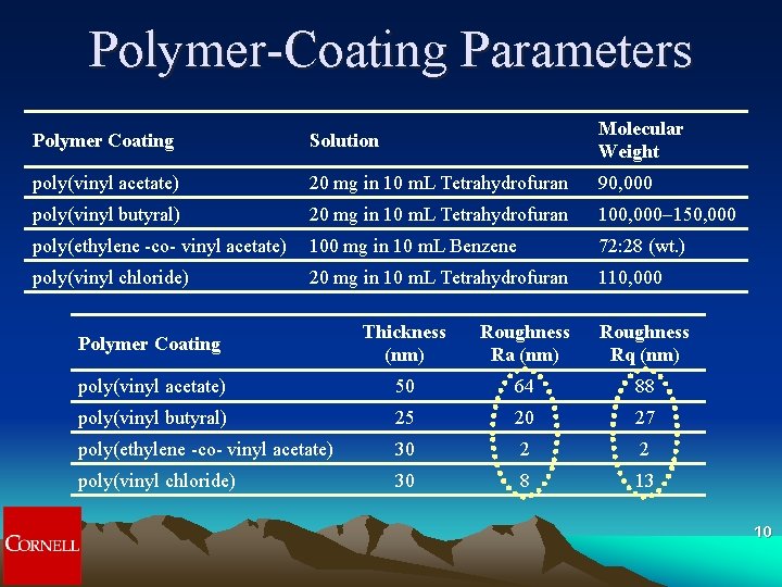
Polymer-Coating Parameters Polymer Coating Solution Molecular Weight poly(vinyl acetate) 20 mg in 10 m. L Tetrahydrofuran 90, 000 poly(vinyl butyral) 20 mg in 10 m. L Tetrahydrofuran 100, 000 -150, 000 poly(ethylene -co- vinyl acetate) 100 mg in 10 m. L Benzene 72: 28 (wt. ) poly(vinyl chloride) 20 mg in 10 m. L Tetrahydrofuran 110, 000 Polymer Coating Thickness (nm) Roughness Ra (nm) Roughness Rq (nm) poly(vinyl acetate) 50 64 88 poly(vinyl butyral) 25 20 27 poly(ethylene -co- vinyl acetate) 30 2 2 poly(vinyl chloride) 30 8 13 10
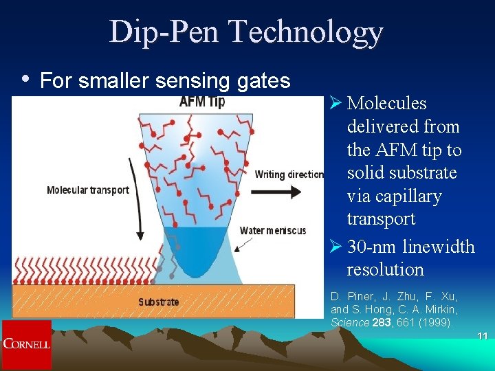
Dip-Pen Technology • For smaller sensing gates Ø Molecules delivered from the AFM tip to solid substrate via capillary transport Ø 30 -nm linewidth resolution D. Piner, J. Zhu, F. Xu, and S. Hong, C. A. Mirkin, Science 283, 661 (1999). 11
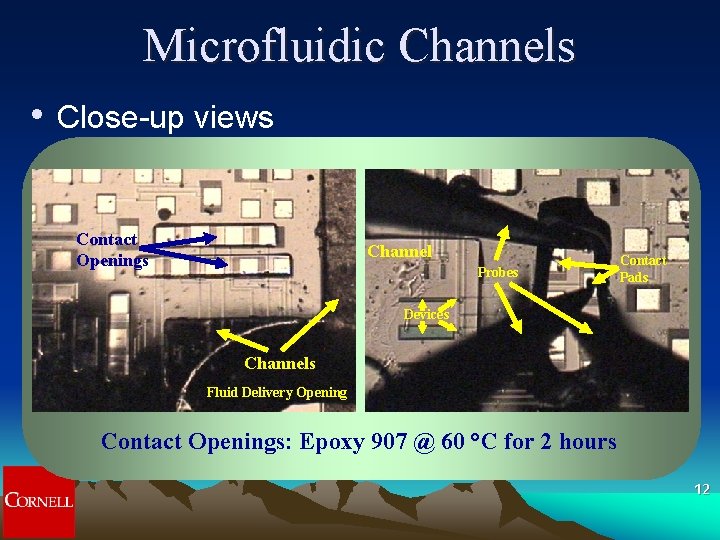
Microfluidic Channels • Close-up views Contact Openings Channel Probes Contact Pads Devices Channels Fluid Delivery Opening Contact Openings: Epoxy 907 @ 60 °C for 2 hours 12
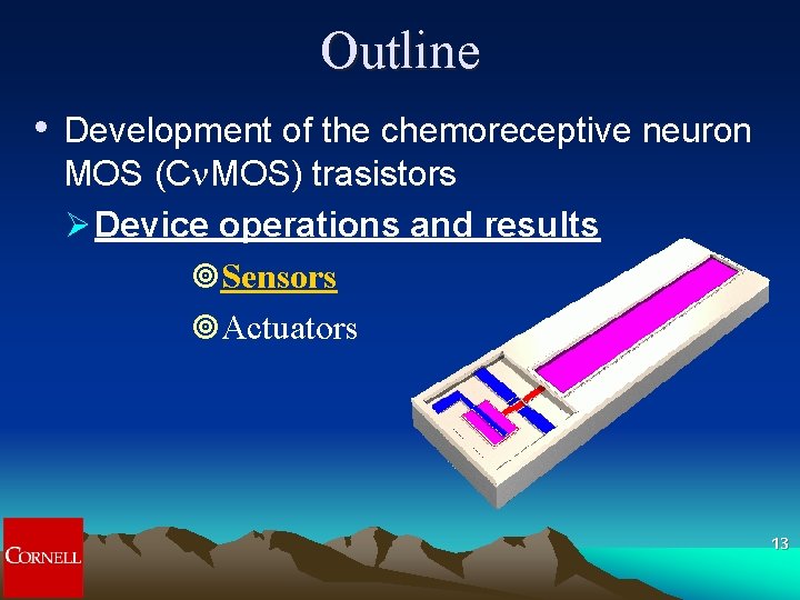
Outline • Development of the chemoreceptive neuron MOS (Cn. MOS) trasistors Ø Device operations and results ¥Sensors ¥Actuators 13
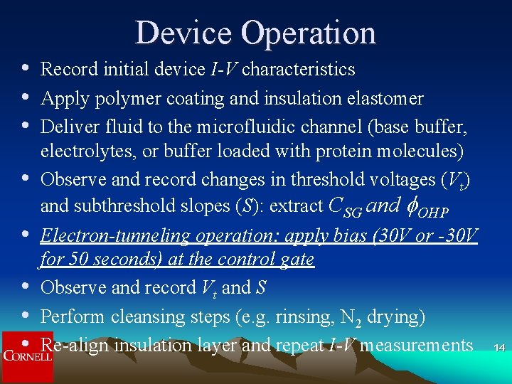
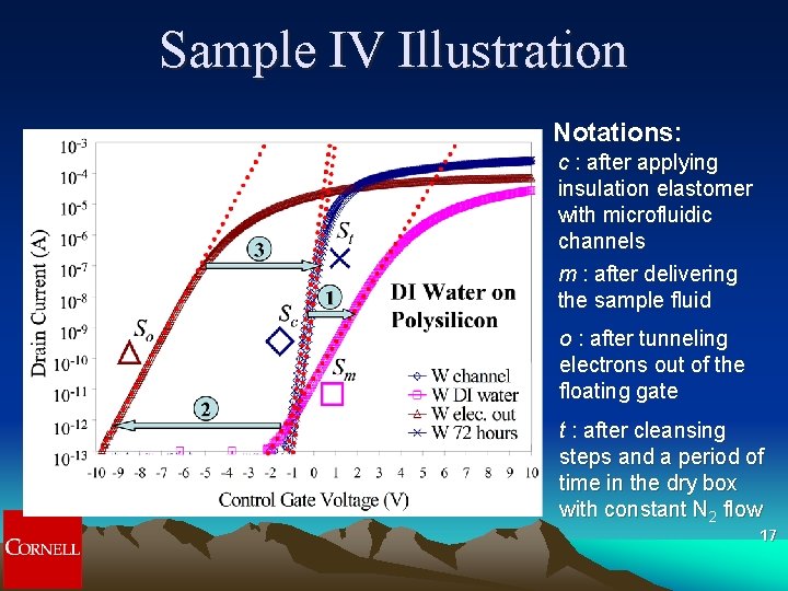
Device Operation • • Record initial device I-V characteristics Apply polymer coating and insulation elastomer Deliver fluid to the microfluidic channel (base buffer, electrolytes, or buffer loaded with protein molecules) Observe and record changes in threshold voltages (Vt) and subthreshold slopes (S): extract CSG and OHP Electron-tunneling operation: apply bias (30 V or -30 V for 50 seconds) at the control gate Observe and record Vt and S Perform cleansing steps (e. g. rinsing, N 2 drying) Re-align insulation layer and repeat I-V measurements 14
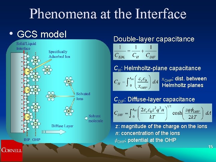
Phenomena at the Interface • GCS model Double-layer capacitance CH: Helmholtz-plane capacitance x. OHP: dist. between Helmholtz planes CDIF: Diffuse-layer capacitance z: magnitude of the charge on the ions n: concentration of the ions OHP: potential at the OHP 15
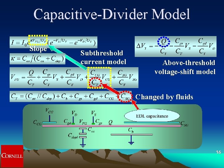
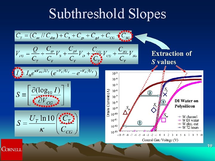
Capacitive-Divider Model Slope Subthreshold current model Above-threshold voltage-shift model Changed by fluids 16
Sample IV Illustration Notations: c : after applying insulation elastomer with microfluidic channels m : after delivering the sample fluid o : after tunneling electrons out of the floating gate t : after cleansing steps and a period of time in the dry box with constant N 2 flow 17
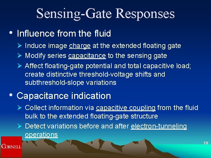
Sensing-Gate Responses • Influence from the fluid Ø Induce image charge at the extended floating gate Ø Modify series capacitance to the sensing gate Ø Affect floating-gate potential and total capacitive load; create distinctive threshold-voltage shifts and subthreshold-slope variations • Capacitance indication Ø Collect information via capacitive coupling from the fluid bulk to the extended floating-gate structure Ø Detect variations before and after electron-tunneling operations 18
Subthreshold Slopes Extraction of S values 19
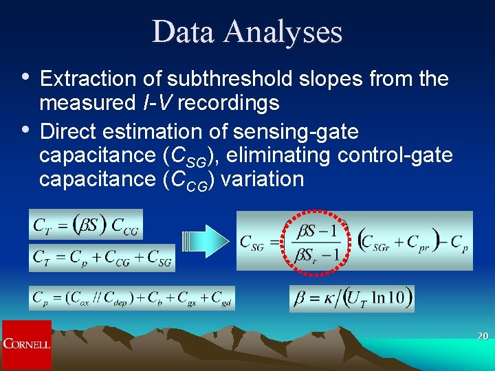
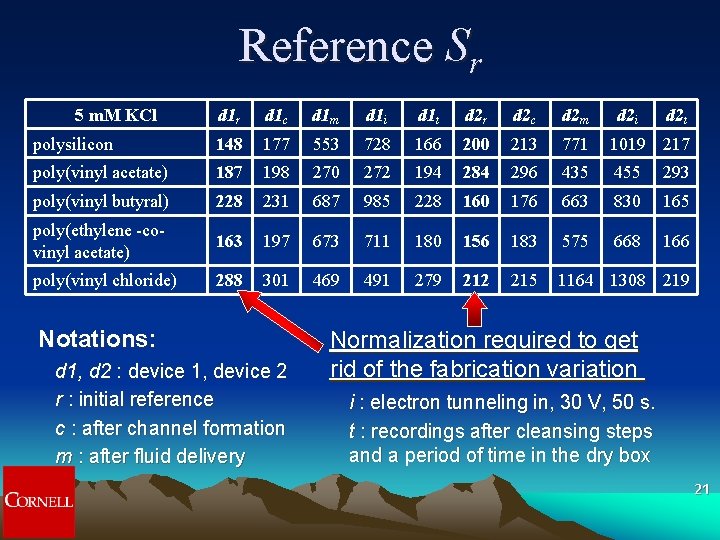
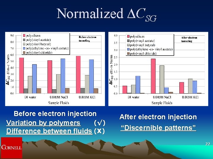
Data Analyses • • Extraction of subthreshold slopes from the measured I-V recordings Direct estimation of sensing-gate capacitance (CSG), eliminating control-gate capacitance (CCG) variation 20
Reference Sr 5 m. M KCl d 1 r d 1 c d 1 m d 1 i d 1 t d 2 r d 2 c d 2 m polysilicon 148 177 553 728 166 200 213 771 1019 217 poly(vinyl acetate) 187 198 270 272 194 284 296 435 455 293 poly(vinyl butyral) 228 231 687 985 228 160 176 663 830 165 poly(ethylene -covinyl acetate) 163 197 673 711 180 156 183 575 668 166 poly(vinyl chloride) 288 301 469 491 279 212 215 1164 1308 219 Notations: d 1, d 2 : device 1, device 2 r : initial reference c : after channel formation m : after fluid delivery d 2 i d 2 t Normalization required to get rid of the fabrication variation i : electron tunneling in, 30 V, 50 s. t : recordings after cleansing steps and a period of time in the dry box 21
Before electron injection (√) Variation by polymers Difference between fluids (X) DCSG Normalized DCSG After electron injection “Discernible patterns” 22
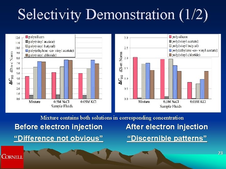
DCSG Selectivity Demonstration (1/2) Mixture contains both solutions in corresponding concentration Before electron injection “Difference not obvious” After electron injection “Discernible patterns” 23
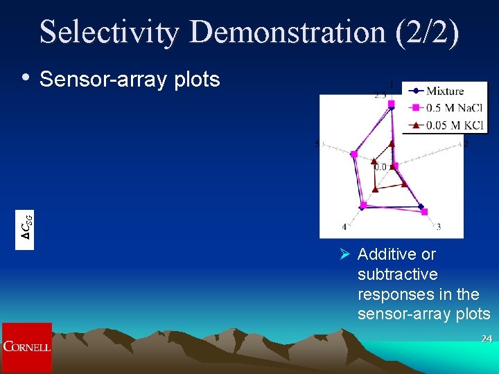
Selectivity Demonstration (2/2) Sensor-array plots DCSG • Ø Additive or subtractive responses in the sensor-array plots 24
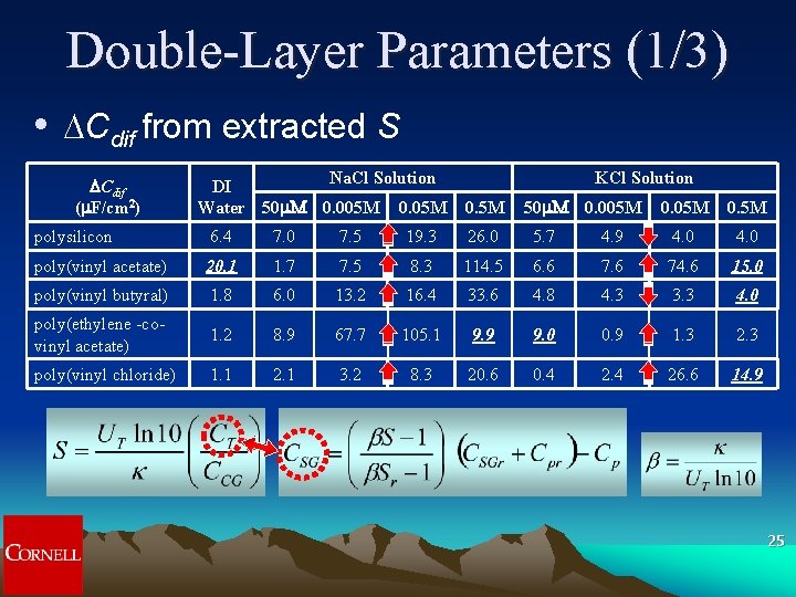
Double-Layer Parameters (1/3) • DCdif from extracted S DCdif (m. F/cm 2) Na. Cl Solution DI Water 50 m. M 0. 005 M 0. 05 M KCl Solution 0. 5 M 50 m. M 0. 005 M 0. 5 M polysilicon 6. 4 7. 0 7. 5 19. 3 26. 0 5. 7 4. 9 4. 0 poly(vinyl acetate) 20. 1 1. 7 7. 5 8. 3 114. 5 6. 6 74. 6 15. 0 poly(vinyl butyral) 1. 8 6. 0 13. 2 16. 4 33. 6 4. 8 4. 3 3. 3 4. 0 poly(ethylene -covinyl acetate) 1. 2 8. 9 67. 7 105. 1 9. 9 9. 0 0. 9 1. 3 2. 3 poly(vinyl chloride) 1. 1 2. 1 3. 2 8. 3 20. 6 0. 4 26. 6 14. 9 25
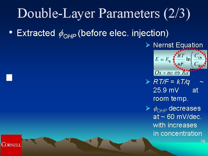
Double-Layer Parameters (2/3) • Extracted OHP (before elec. injection) Ø Nernst Equation Ø RT/F = k. T/q ~ 25. 9 m. V at room temp. Ø OHP decreases at ~ 60 m. V/dec. with increases in concentration 26
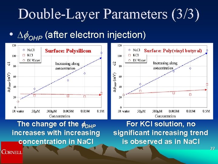
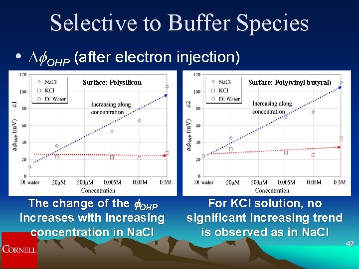
Double-Layer Parameters (3/3) • D OHP (after electron injection) Surface: Polysilicon The change of the f. OHP increases with increasing concentration in Na. Cl Surface: Poly(vinyl butyral) For KCl solution, no significant increasing trend is observed as in Na. Cl 27
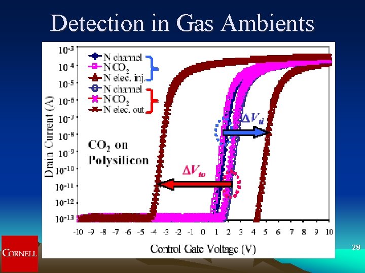
Detection in Gas Ambients 28
Protein Sensing 29 BSA: bovine serum albumin SDS: sodium dodecyl sulfate
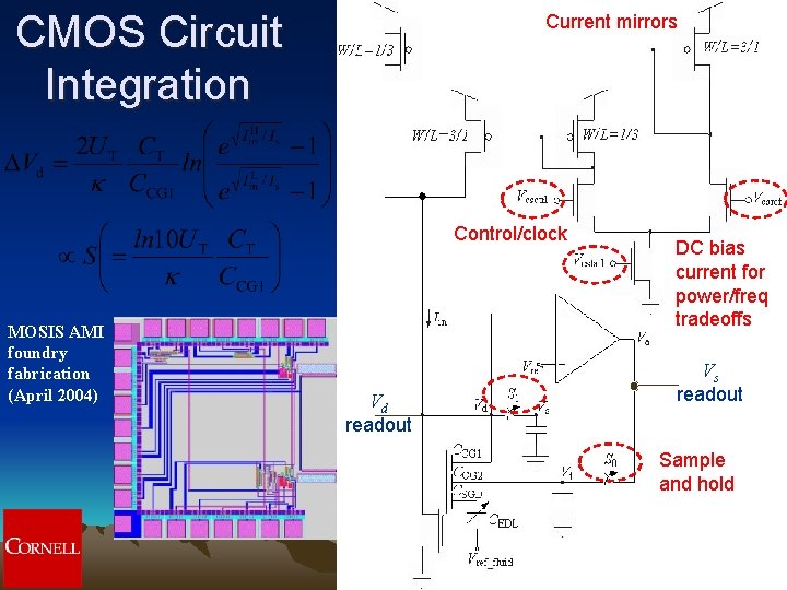
CMOS Circuit Integration Current mirrors Control/clock MOSIS AMI foundry fabrication (April 2004) Vd readout DC bias current for power/freq tradeoffs Vs readout Sample and hold 30
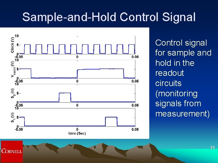
Sample-and-Hold Control Signal Control signal for sample and hold in the readout circuits (monitoring signals from measurement) 31
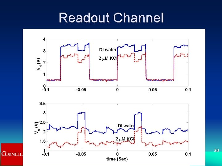
Readout Calibration Quasi-static operations with reliable resets 32
Readout Channel 33
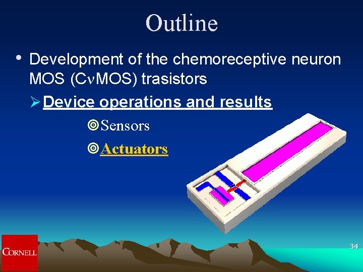
Outline • Development of the chemoreceptive neuron MOS (Cn. MOS) trasistors Ø Device operations and results ¥Sensors ¥Actuators 34
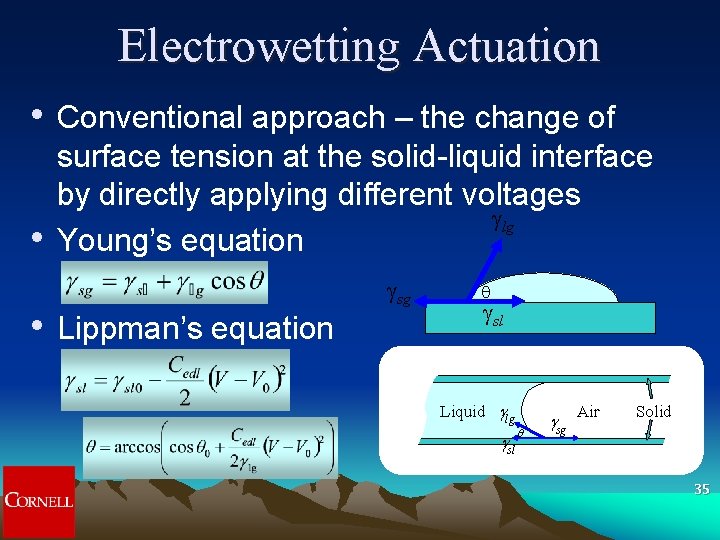
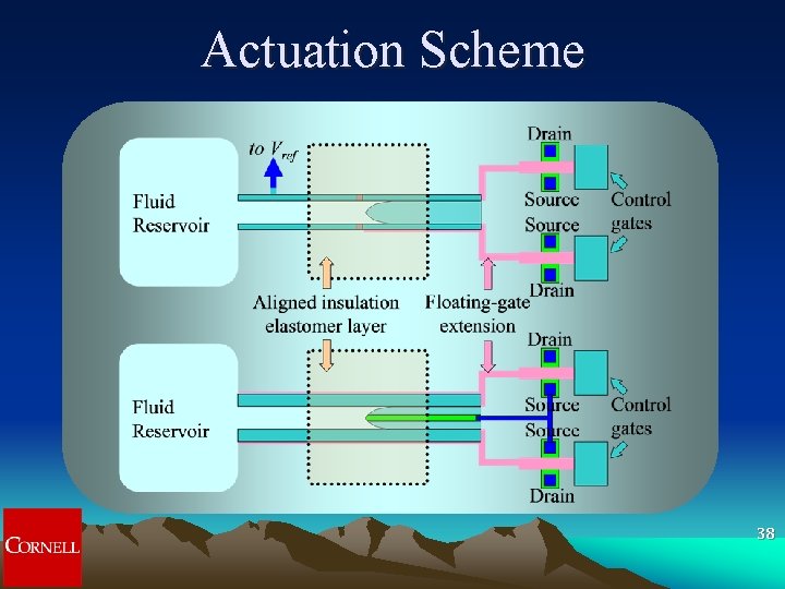
Electrowetting Actuation • • • Conventional approach – the change of surface tension at the solid-liquid interface by directly applying different voltages lg Young’s equation sg Lippman’s equation sl Liquid glg gsl q gsg Air Solid 35
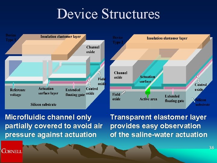
Device Structures Microfluidic channel only Transparent elastomer layer partially covered to avoid air provides easy observation pressure against actuation of the saline-water actuation 36
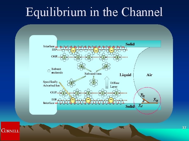
Equilibrium in the Channel 37
Actuation Scheme 38
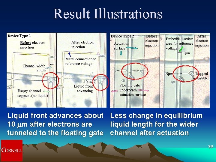
Result Illustrations Type 1 Liquid front advances about Less change in equilibrium 10 mm after electrons are liquid length for the wider tunneled to the floating gate channel after actuation 39
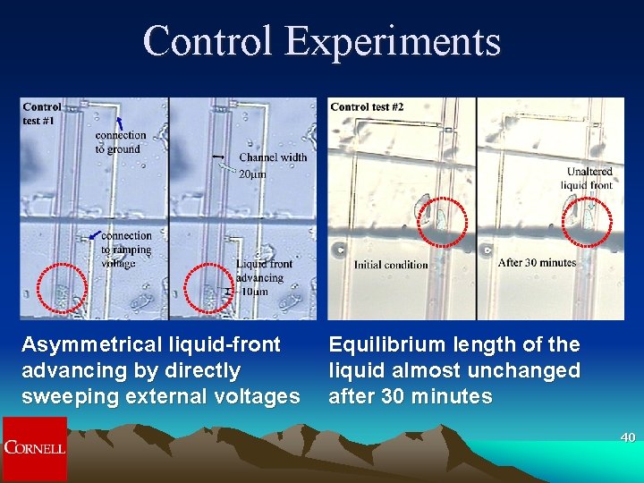
Control Experiments Asymmetrical liquid-front advancing by directly sweeping external voltages Equilibrium length of the liquid almost unchanged after 30 minutes 40
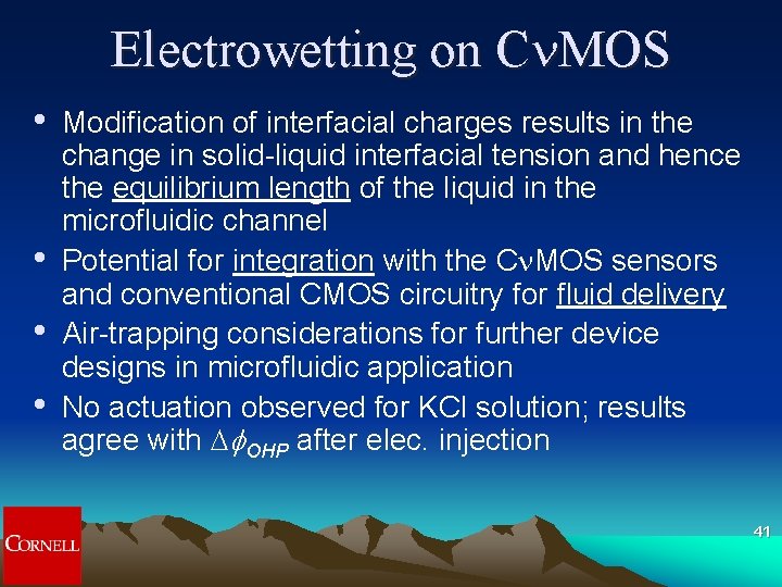
Electrowetting on Cn. MOS • • Modification of interfacial charges results in the change in solid-liquid interfacial tension and hence the equilibrium length of the liquid in the microfluidic channel Potential for integration with the Cn. MOS sensors and conventional CMOS circuitry for fluid delivery Air-trapping considerations for further device designs in microfluidic application No actuation observed for KCl solution; results agree with D OHP after elec. injection 41
Selective to Buffer Species • D OHP (after electron injection) Surface: Polysilicon The change of the f. OHP increases with increasing concentration in Na. Cl Surface: Poly(vinyl butyral) For KCl solution, no significant increasing trend is observed as in Na. Cl 42
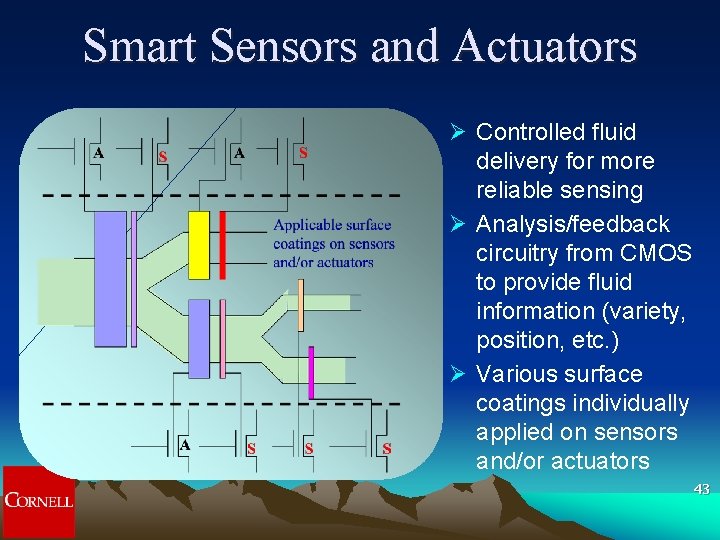
Smart Sensors and Actuators Ø Controlled fluid delivery for more reliable sensing Ø Analysis/feedback circuitry from CMOS to provide fluid information (variety, position, etc. ) Ø Various surface coatings individually applied on sensors and/or actuators 43
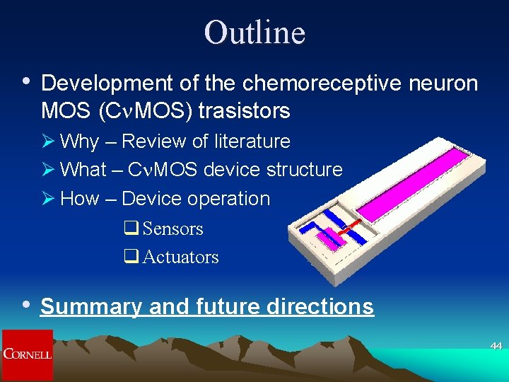
Outline • Development of the chemoreceptive neuron MOS (Cn. MOS) trasistors Ø Why – Review of literature Ø What – Cn. MOS device structure Ø How – Device operation q Sensors q Actuators • Summary and future directions 44
Summary (1/2) • • FET devices with extended floating gates for chemical sensing Floating-gate structure for electron-tunneling operations provides more DOFs for sensing Indicators from I-V characteristics: Subthreshold slopes (S) and threshold voltages (Vt) CMOS integration enables detailed control circuits 45
Summary (2/2) • • Normalized DCSG in the polymeric responses directly couples to subthreshold slopes and the patterns encourage sensor-array application in the lock-and-key implementation Electrowetting actuator for potential microvalves integrated with the sensors and conventional CMOS circuitry for fluid delivery and confinement 46