Special Casting Processes Shell Casting Investment Casting Centrifugal


")


 Two halves of a shell-mold pattern. (Bottom) The")


 Schematic illustration of the semi centrifugal casting process. Wheels")


 Single – cavity die")


- Slides: 45
Special Casting Processes
• Shell Casting • Investment Casting • Centrifugal Casting • Die Casting • Ceramic Mould • CO 2 Moulding
SHELL CASTING • • • Preparation of Metal Match plate pattern Mix the investment material Heat the pattern Invest the pattern Curing the shell Remove the shell Assemble the shells Pour the metal Remove the casting
Shell Molding / Croning or Cprocess • A heated (200 ºC to 300 ºC ) metal pattern is covered with a mixture of fine sand 5 – 10 % of thermosetting phenolic resin( phenol formaldehyde) which acts as binder • To prevent the sticking of shell with the pattern a release agent Silicone is sprayed over the hot pattern.
• This causes a skin of about 3. 5 mm (0. 125 in) of sand/plastic mixture to adhere to the pattern. • The shell thickness will depend upon the time of contact of mixture with the heated pattern
• Once more heated for around 420 ºC for 3 min for curing of shell • This skin is removed from the pattern to form the "shell mold".
• The two halves of the shell mold are secured together and the metal is poured in the shell to form the part. • Once the metal solidifies, the shell is broken.
Shell Molding
Advantages • Better surface finish, • Better dimensional tolerances, • Higher throughput due to reduced cycle times. • Less sand is used • This process can produce complex parts with good surface finish 1. 25 µm to 3. 75 µm and dimensional tolerance of 0. 5% • A fairly high capital investment is required, but high production rates can be achieved. The process overall is quite cost effective due to reduced machining and cleanup costs.
Dis advantages • • High pattern cost and resin cost Un economical for small runs Size of the casting is limited Serious dust and fume problems
Shell Molding • The materials that can be used with this process are cast irons, and aluminum and copper alloys. • Typical parts made with this process are connecting rods, gear housings, lever arms etc.
Shell-Mold Casting Figure 12 -19 (Top) Two halves of a shell-mold pattern. (Bottom) The two shells before clamping, and the final shell-mold casting with attached pouring basin, runner, and riser. (Courtesy of Shalco Systems, Lansing, MI. )
INVESTMENT CASTING • Investment casting is also called lost-wax process or precision Investment Casting • metals that are hard to machine or fabricate are good candidates for this process. • The mold is made by making a pattern using wax or some other material that can be melted away. • Term investment derives from the fact that the pattern is invested with the refractory material
INVESTMENT CASTING • This wax pattern is dipped in refractory slurry, which coats the wax pattern and forms a skin. • Slurry – Fine silica sand + water/ethyl silicate or Gypsum solution • This is dried and the process of dipping in the slurry and drying is repeated until a robust thickness is achieved. • After this, the entire pattern is placed in an oven and the wax is melted away. • This leads to a mold that can be filled with the molten metal. • Because the mold is formed around a one-piece pattern, (which does not have to be pulled out from the mold as in a traditional sand casting process), very intricate parts and undercuts can be made
Step by step procedure • Make a master pattern of the part to be cast (metal easily machined such as brass, Aluminum alloy, alloy of tin lead bismuth) • Making a master dies
Schematic illustration of investment casting 1. WAX INJECTION : Wax replicas of the desired castings are produced by injection molding. These replicas are called patterns. 2. ASSEMBLY : The patterns are attached to a central wax stick, called a sprue, to form a casting cluster or assembly. 3. SHELL BUILDING : The shell is built by immersing the assembly in a liquid ceramic slurry and then into a bed of extremely fine sand. Up to eight layers may be applied in this manner. 4. DEWAX : Once the ceramic is dry, the wax is melted out, creating a negative impression of the assembly within the shell.
• 5. CONVENTIONAL CASTING In the conventional process, the shell is filled with molten metal by gravity pouring. As the metal cools, the parts and gates, sprue and pouring cup become one solid casting. • 6. KNOCKOUT When the metal has cooled and solidified, the ceramic shell is broken off by vibration or water blasting. • 7. CUT OFF The parts are cut away from the central sprue using a high speed friction saw. • 8. FINISHED CASTINGS After minor finishing operations, the metal castings--identical to the original wax patterns-are ready for shipment to the customer.
Casting with expendable mould: Investment Casting
Advantages and Limitations • • • Parts of greater complexity and intricacy can be cast Close dimensional control 0. 075 mm Superior surface finish Un machinable Alloys can be cast The lost wax can be reused Additional machining is not required in normal course • Preferred for casting weight less than 5 kg, ( weighing 1 g – 35 Kg) • Maximum dimension less than 300 mm, Thickness is usually restricted to 15 mm • High-melting point alloys • Al, Cu, Ni, Carbon and alloy steels, tool steels etc. are the common materials • Not a cheap process
CENTRIFUGAL CASTING
CENTRIFUGAL CASTING §In centrifugal casting, a permanent mold is rotated about its axis at high speeds (300 to 3000 rpm) as the molten metal is poured. §The molten metal is centrifugally thrown towards the inside mold wall, where it solidifies after cooling. §The casting is usually a fine grain casting with a very fine-grained outer diameter, which is resistant to atmospheric corrosion, a typical situation with pipes. §The inside diameter has more impurities and inclusions, which can be machined away.
• Only cylindrical shapes can be produced with this process. Size limits are upto 3 m (10 feet) diameter and 15 m (50 feet) length. • Typical materials that can be cast with this process are iron, steel, stainless steels, and alloys of aluminum, copper and nickel. • Two materials can be cast by introducing a second material during the process. • Typical parts made by this process are pipes, boilers, pressure vessels, flywheels, cylinder liners and other parts that are axi-symmetric.
Semi centrifugal Casting Process (a) Schematic illustration of the semi centrifugal casting process. Wheels with spokes can be cast by this process. (b) Schematic illustration of casting by centrifuging. The molds are placed at the periphery of the machine, and the molten metal is forced into the molds by centrifugal force.
DIE-CASTING • In Die-casting the metal is injected into the mold under high pressure of 10210 Mpa • The mould used for making a casting is permanent, called Die. • Hot Chamber • Cold Chamber
Cold-chamber – molten metal is poured in to the injection chamber & the shot chamber is not heated • In a cold chamber process, the molten metal is ladled into the cold chamber for each shot. There is less time exposure of the melt to the plunger walls or the plunger. This is particularly useful for metals such as Aluminum, and Copper (and its alloys) that alloy easily with Iron at the higher temperatures.
Hot-chamber - involves the use of a piston to push molten metal in to the die cavity • In a hot chamber process the pressure chamber is connected to the die cavity is immersed permanently in the molten metal. The inlet port of the pressurizing cylinder is uncovered as the plunger moves to the open (unpressurized) position. This allows a new charge of molten metal to fill the cavity and thus can fill the cavity faster than the cold chamber process. The hot chamber process is used for metals of low melting point and high fluidity such as tin, zinc, and lead that tend not to alloy easily with steel at their melt temperatures.
Die Casting • Parts made from here range from: – Hand tools – Building Hardware – Automobile – Telecommuniction – Toys – Appliance components
• In Die casting the molten metal is forced to flow into a permanent metallic mold under moderate to high pressures, and held under pressure during solidification • This high pressure forces the metal into intricate details, produces smooth surface and excellent dimensional accuracy • High pressure causes turbulence and air entrapment. In order to minimize this larger ingates are used and in the beginning pressure is kept low and is increased gradually
Cycle in Hot Chamber Casting
Hot chamber Die-casting process • 1. The die is closed and the piston rises, opening the port and allowing molten metal to fill the cylinder. • 2. The plunger moves down and seals the port pushing the molten metal through the gooseneck and nozzle into the die cavity, where it is held under pressure until it solidifies.
• 3. The die opens and the cores, if any, retract. The casting remains in only one die, the ejector side. The plunger returns, allowing residual molten metal to flow back through the nozzle and gooseneck. • 4. Ejector pins push the casting out of the ejector die. As the plunger uncovers the filling hole, molten metal flows through the inlet to refill the gooseneck, as in step (1).
Cycle in Cold Chamber Casting
Cold-Die casting process • 1. The die is closed and the molten metal is ladled into the cold-chamber shot sleeve. • 2. The plunger pushes the molten metal into the die cavity where it is held under pressure until solidification.
• 3. The die opens and the plunger advances, to ensure that the casting remains in the ejector die. Cores, if any, retract. • 4. Ejector pins push the casting out of the ejector die and the plunger returns to its original position.
Process Capabilities and Machine Selection – Dies are rated according to their clamping force that is needed – Factors involved in selection of die cast machines are • Die size • Piston stroke • Shot pressure • Cost – Die-casting dies • Single cavity • Multiple-cavity • Combination-cavity • Unit dies – Ratio of Die weight to part weight is 1000 to 1 – Surface cracking is a problem with dies due to the hot metal that is poured in to them – Has ability to produce strong high- quality parts with complex shapes – Good dimensional accuracy and surface details
Various types of cavities in a die casting die. a) Single – cavity die b) Multiple – cavity die c) Combination die d) Unit die
Permanent mould casting: Die casting Graphite+oil
• 800 ton hot chamber die casting machine, DAM 8005. This is the largest hot chamber machine in the world and costs about $1. 25 million.
General Configuration of a Die Casting Machine
Advantages of Die Casting High production rates § Closer dimensional tolerances § Superior surface finish § Improved mechanical properties §
Ceramic-Shell Casting – Variation of the investment-casting process – Uses same type of wax or plastic pattern as investment casting – Patten is then dipped into fluidized bed of • Fine- grained fused silica • Zircon flour – Pattern is then dipped into coarser grained silica to build up additional coatings and proper thickness to withstand thermal shock of pouring – The rest of the procedure follows the investment casting process Fig : Investment casting of an integrally cast rotor for a gas turbine. (a) Wax pattern assembly. (b) Ceramic shell around wax pattern. (c) Wax melted out and the mold is filled under a vacuum, with molten super alloy. (d) The cast rotor produced to net or near-net shape.
Ceramic mold casting • This process is expensive, but can eliminate secondary machining operations. Typical parts made from this process include impellers made from stainless steel, bronze, complex cutting tools, plastic mold tooling.
CO 2 Moulding • A sand molding technique and uses sand grain in which is mixed a solution of sodium silicate that acts to bind the sand particles. • CO 2 gas is used to harden the sand after the mould has been prepared. • H 2 O+Na 2 Si. O 3+ CO 2 →Na 2 CO 3+Si. O 2
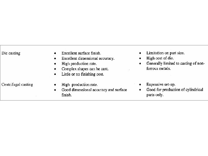
Comparison of Casting Processes