3 2Permitted locations for laying Track Structure Laying

- Slides: 77
3. 2_Permitted locations for laying, Track Structure, Laying of LWR. Periods- 1
PERMITTED LOCATIONS FOR LAYING TRACK STRUCTURE, LAYING OF LWR
Long Welded Rail (LWR) is a welded rail, the central part of which does not undergo any longitudinal movement due to temperature variations. A length of welded rail greater than 250 m on Broad Gauge will normally function as LWR.
PERMITTED LOCATIONS FOR LWR/CWR • (1) General Considerations for laying LWR/CWR: • (a) All new constructions/doublings/gauge conversions, permanent diversion shall be opened with LWR/CWR. • (b) All CTR/TSR/TRR (Primary) shall provide for LWR/CWR, wherever permissible.
PERMITTED LOCATIONS FOR LWR/CWR • (1) General Considerations for laying LWR/CWR: • (c) The existing rails on permitted locations may also be converted into LWR/CWR, provided they meet the requirements for Welding of Rail Joints by Alumino Thermic (SKV Process)/Flash Butt Process, as the case may be.
PERMITTED LOCATIONS FOR LWR/CWR • (1) General Considerations for laying LWR/CWR: (d) In yard lines, rail joints may be welded to form LWR if the condition of all the components of track is generally sound and without any deficiency, subject to such relaxation as may be approved by Chief Track Engineer, in each specific case.
PERMITTED LOCATIONS FOR LWR/CWR • (2) Alignment: • (a) LWR/CWR shall not be laid on curves sharper than 440 m radius. However, in temperature Zone-I, LWR/CWR may be laid on curves up to 350 m radius (5 o Curve) with following additional precautions: • (i) Minimum track structure should be 52 kg/m rails on PSC sleeper 1540 sleeper density with 300 mm clean ballast cushion.
PERMITTED LOCATIONS FOR LWR/CWR • (2) Alignment: • (ii) Shoulder ballast for curves shaper than 440 m radius should be increased to 600 mm on outside of curve and should be provided for 100 m beyond the tangent point. • (iii) Reference marks should be provided at every 50 m interval to record creep.
PERMITTED LOCATIONS FOR LWR/CWR • (2) Alignment: • (iv) Each curve of length greater than 250 m should preferably be provided with SEJ on either side. SEJ should be located in straight track at 100 m away from the tangent point.
PERMITTED LOCATIONS FOR LWR/CWR • (2) Alignment: • (b) LWR/CWR may be continued through reverse curves. Shoulder ballast of 600 mm over a length of 100 m on both side of the common point of a reverse curve would be provided. In case there is a straight track between the reverse curves, this 100 m would be considered from the center of the straight track. No such measure would be required if the length of straight track between the reverse curves is more than 50 m.
PERMITTED LOCATIONS FOR LWR/CWR • (3) Gradient: • The steepest permitted grade for LWR/CWR shall be 1 in 100.
PERMITTED LOCATIONS FOR LWR/CWR • (4) Approvals & deviations: • Installation of LWR/CWR, or change in its constitution at a later stage shall have the approval of the Chief Track Engineer in each case, on a detailed plan prepared in accordance with IRPWM Para 336 (1) (c). However, for any deviation from this provision, approval of Principal Chief Engineer shall be obtained.
PERMITTED LOCATIONS FOR LWR/CWR • (5) Track structure for LWR/CWR: • (a) LWR/CWR shall be laid on stable formation having stipulated formation width and ballast cushion (below the bottom of the sleeper); and with approved PSC sleepers and its matching fastening system. • (b) The minimum rail section to be used shall be of 52 kg/m. • (c) In a LWR/CWR, two different rail sections are not permitted.
PERMITTED LOCATIONS FOR LWR/CWR • (5) Track structure for LWR/CWR: • (d) In case of LWRs laid on concrete sleepers having different rail section on either side of SEJs, combination SEJ to RDSO Drg. No T-6782 (52 kg / 60 Kg) shall be provided. Alternatively, two 3 rail panels (39 m), one of each rail section shall be provided with combination fish plated joint, between the two panels.
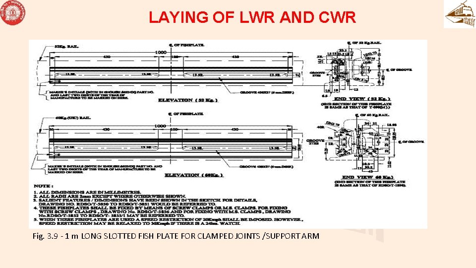
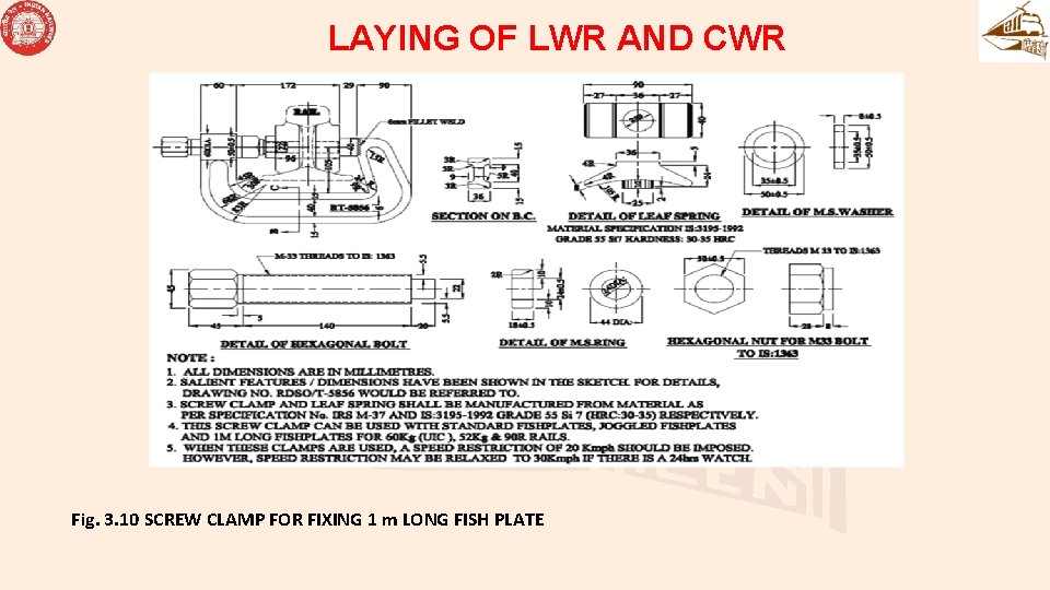
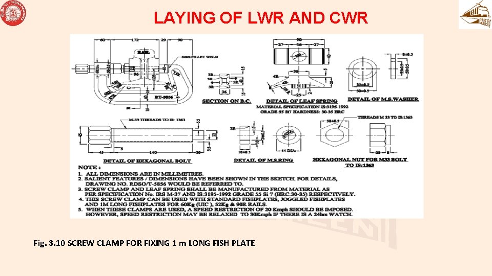
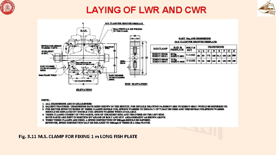
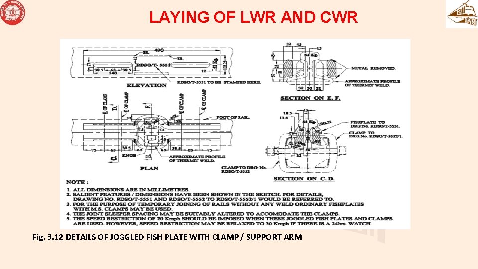
PERMITTED LOCATIONS FOR LWR/CWR • (5) Track structure for LWR/CWR: • (e) New rails used in LWR/CWR shall, as far as possible, be without fish-bolt holes. Joining of rail ends temporarily during installation of LWR/CWR shall be done by 1 m long fishplates with special screw clamps/joggled fish-plates having slotted grooves & bolted clamps as in Fig. 3. 9, 3. 10, 3. 11, 3. 12, 3. 13 with speed restrictions indicated in Annexure -3/8.
PERMITTED LOCATIONS FOR LWR/CWR
PERMITTED LOCATIONS FOR LWR/CWR • (f) Bolt holes, if any, shall be chamfered. • (6) Continuity of track structure: • Wherever LWR/CWR is followed by fish-plated track/SWR, the same track structure as that of LWR/CWR shall be continued for at least three rail lengths (39 m) beyond SEJ. • (7) Level crossings: • Level crossings situated in LWR/CWR territory shall not fall within the breathing lengths. • (8) Points and Crossings: • (a) In case, LWR is terminated near Points & Crossings, one three rail panel (39 m) shall be provided between stock rail joint (SRJ) and SEJ as well as between the crossing and SEJ. This length shall be provided with elastic fastenings with adequate toe load to arrest creep. • (b) In case, LWR/CWR is taken through Points & Crossings, the provisions contained in RDSO report no. CT-48 shall be followed.
PERMITTED LOCATIONS FOR LWR/CWR • (f) Bolt holes, if any, shall be chamfered. • (6) Continuity of track structure: • Wherever LWR/CWR is followed by fish-plated track/SWR, the same track structure as that of LWR/CWR shall be continued for at least three rail lengths (39 m) beyond SEJ.
PERMITTED LOCATIONS FOR LWR/CWR • (5) Track structure for LWR/CWR: • (7) Level crossings: • Level crossings situated in LWR/CWR territory shall not fall within the breathing lengths.
PERMITTED LOCATIONS FOR LWR/CWR • (5) Track structure for LWR/CWR: • (8) Points and Crossings: • (a) In case, LWR is terminated near Points & Crossings, one three rail panel (39 m) shall be provided between stock rail joint (SRJ) and SEJ as well as between the crossing and SEJ. This length shall be provided with elastic fastenings with adequate toe load to arrest creep. • (b) In case, LWR/CWR is taken through Points & Crossings, the provisions contained in RDSO report no. CT-48 shall be followed.
PERMITTED LOCATIONS FOR LWR/CWR • Provision of Glued Joints: • All insulations for track circuiting in LWR/CWR shall be done by providing glued joints of G 3(L) type.
Location of SEJ • The exact location of SEJ shall be fixed taking into account the location of various obligatory points such as level crossings, bridges, points and crossings, gradients, curves and insulated joints. • The various designs of SEJs in use on Indian Railways are as per Para 227
Location of SEJ • (1)The conventional SEJ (RT-4160 and RT 4165) with straight tongue and stock shall not be located on curves sharper than 0. 5° (3500 m radius).
Location of SEJ (2) The improved SEJs (RT-6902, RT-6914, RT-6922, RT-6930) may be located on curves up to 2°. SEJ beyond 2° and up to 4° shall be laid with approval of PCE in consultation with RDSO • (3) The SEJ shall not be located on transition of curves.
Bridges with ballasted deck (without bearing) • LWR/CWR can be continued over bridges with ballasted deck without bearings like slabs, box culverts and arches.
Bridges with ballasted deck (with bearing): • Detailed calculations shall be done by the Design office of Chief Bridge Engineer / CAO(C) to ascertain the effect of LWR of such bridges and its effect on the Sub-structure of the bridge as per Para 2. 8. 1. 2 of “Bridge Rules”.
Bridges with ballasted deck (with bearing): • The LWR/CWR may be permitted on a case-to-case basis based on the above calculations. In case detailed calculations are not done, LWR may be permitted as per Para 331 below for bridges with unballasted deck.
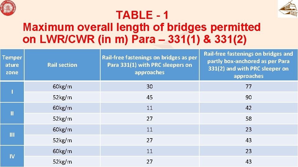
Bridges with un-ballasted deck • LWR/CWR shall be continued over such bridges with overall length as specified in sub-para (1) to (3) below: • (1) Bridges provided with rail-free fastenings (single span not exceeding 30. 5 metre and having sliding bearings on both ends)
Bridges with un-ballasted deck Overall length of the bridge should not exceed the maximum as provided in Table-1 with following stipulations: • (a) Rail-free fastenings shall be provided throughout the length of the bridge between abutments. .
Bridges with un-ballasted deck • (b) SEJ of the LWR should be located such that bridge does not fall in the breathing length of the LWR. The approach track upto 50 m on both sides shall be well anchored by providing PRC sleepers with elastic rail clips with adequate toe load so as to arrest creep.
Bridges with un-ballasted deck • (c) The ballast section of approach track upto 50 metre shall be heaped upto the foot of the rail on the shoulders and kept in well-compacted and consolidated condition during the months of extreme summer and winter.
Bridges with un-ballasted deck • (2) Bridges provided with rail-free fastenings and partly box-anchored (with single span not exceeding 30. 5 metre and having sliding bearings at both ends) • Overall length of the bridge should not exceed the maximum as provided in Table-1 with following stipulations:
Bridges with un-ballasted deck • (a) Central sleepers shall be anchored with anchoring arrangement (two each in end spans and one each in the middle spans) as per RDSO Drg. No. M-10920(1) (Fig 3. 26) and the remaining sleepers shall be provided with rail-free fastenings. • (b) The track structure in the approaches shall be laid and maintained to the standards as stated in (1) (b) & (c) above.
Bridges with un-ballasted deck • (c) The girders shall be centralized with reference to the location strips on the bearing, before laying LWR/CWR. • (d) The sliding bearings shall be inspected during the months of March and October each year and cleared of all foreign materials. Lubrication of the bearings shall be done once in two years.
TABLE - 1 Maximum overall length of bridges permitted on LWR/CWR (in m) Para – 331(1) & 331(2) Temper ature zone I II IV Rail section Rail-free fastenings on bridges as per Para 331(1) with PRC sleepers on approaches Rail-free fastenings on bridges and partly box-anchored as per Para 331(2) and with PRC sleeper on approaches 60 kg/m 30 77 52 kg/m 45 90 60 kg/m 11 42 52 kg/m 27 58 60 kg/m 11 23 52 kg/m 27 43
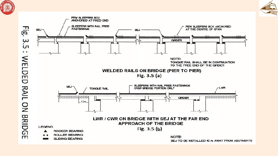
Bridges with un-ballasted deck • (3) LWR/CWR may also be continued over a bridge with the provision of SEJ at the far end approach of the bridge using rail-free fastenings over the girder bridge. The length of the bridge in this case, however, will be restricted by the capacity of the SEJ to absorb expansion, contraction and creep, if any, of the rails.
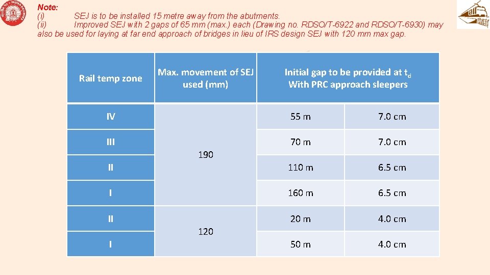
Bridges with un-ballasted deck The length of the bridge in this case, however, will be restricted by the capacity of the SEJ to absorb expansion, contraction and creep, if any, of the rails. The length of the bridges with the above arrangement that can be permitted in various rail temperature zones for LWR/CWR with SEJs having maximum movement of 120 mm and 190 mm are as under: • (3)
Note: (i) SEJ is to be installed 15 metre away from the abutments. (ii) Improved SEJ with 2 gaps of 65 mm (max. ) each (Drawing no. RDSO/T-6922 and RDSO/T-6930) may also be used for laying at far end approach of bridges in lieu of IRS design SEJ with 120 mm max gap. Rail temp zone Max. movement of SEJ used (mm) Initial gap to be provided at td With PRC approach sleepers IV 55 m 7. 0 cm III 70 m 7. 0 cm II 110 m 6. 5 cm I 160 m 6. 5 cm II 20 m 4. 0 cm 50 m 4. 0 cm 190 120 I
Bridges with un-ballasted deck • (4) Welded rails may be provided from pier to pier with rail-free fastenings and with SEJ on each pier. The rail shall be box-anchored on four sleepers at the fixed end of the girder is supported on rollers on one side and rockers on other side. In case of girder supported on sliding bearings on both sides, the central portion of the welded rails over each span shall be box-anchored on four sleepers
Bridges with un-ballasted deck • (5) Welded rails may be provided over a single span bridge with rail free fastenings and SEJs with 190 mm gap at 30 m away from both abutments. The rail shall be box anchored on four sleepers at the fixed end of the bridge if bridge is supported on rollers on one side and rockers on other side.
Bridges with un-ballasted deck • (5) In case of bridge supported on sliding bearings on both sides, the central portion of the welded rails shall be box anchored on four sleepers. The approach track upto 50 m on both sides shall be well anchored by PRC sleepers with elastic rail clips with minimum toe load as specified. The installation temperature of such welded panels shall be equal to tm.
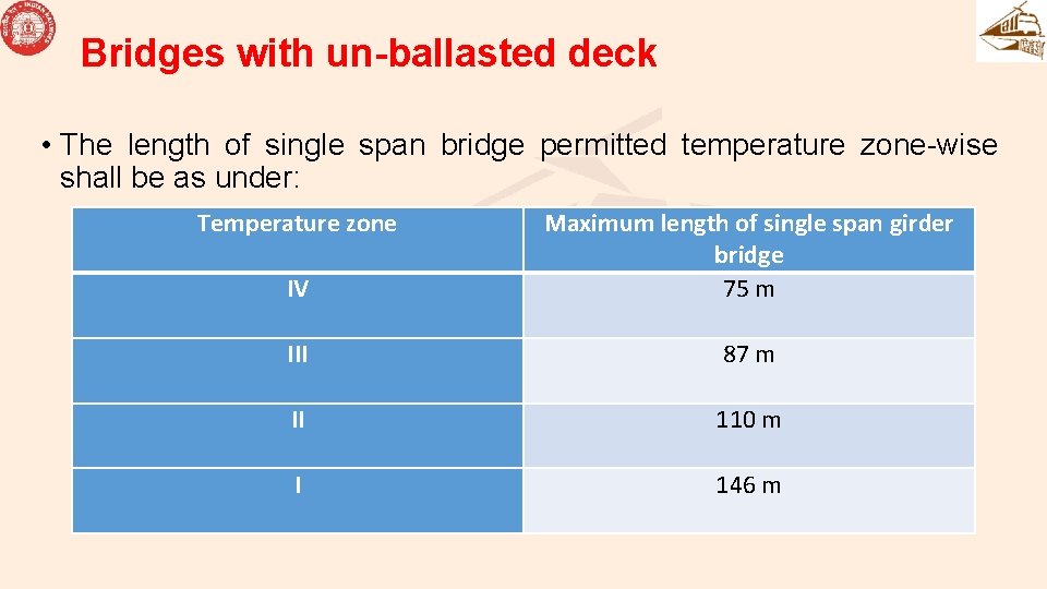
Bridges with un-ballasted deck • The length of single span bridge permitted temperature zone-wise shall be as under: Temperature zone IV Maximum length of single span girder bridge 75 m III 87 m II 110 m I 146 m
Bridges with un-ballasted deck • (6) Bridges on which LWR/CWR is not permitted/provided as per above shall be isolated by a minimum length of 30 metre of well anchored PSC sleeper track on either sides
Bridges with un-ballasted deck • (7) In case of LWR is continued over bridges as per Para 331 (3) above, the measurement of gaps of stock rail / tongue rail tip of SEJ provided at bridge approach from the reference post shall be compared with theoretical gaps as prescribed in Annexure 3/9 A. • (8) In case welded rails are provided as per Para 331 (4) or (5) above, these shall not be entered in TMS as LWR and accordingly, measurement of gaps of at such SEJs of welded panels is not warranted.
LAYING OF LWR AND CWR • (1) Survey: • (a) A foot by foot survey of the sections where LWR/CWR is proposed to be laid shall be carried out in regard to the Locations over which LWR/CWR cannot be carried through on account of constraints such as bridges having substructure/superstructure in a distressed condition, curves, gradients, points and crossings, unstable formation etc. Such stretches of track shall be isolated from the remaining portion of LWR/CWR by provision of SEJs at either end.
LAYING OF LWR AND CWR • (1) Survey: • (b) Locations where following preliminary works are required to be carried out shall be identified for completion before laying of LWR/CWR: • (i) Replacement of insulated joints by glued joints • (ii) Realignment of curves • (iii) Lifting or lowering of track to eliminate sags and humps
LAYING OF LWR AND CWR • (1) Survey: • (iv) Introduction and improvement of vertical curves • (v) Stabilisation of troublesome formation • (vi) Rehabilitation of weak bridges involving removal or lifting of rails or introduction of temporary arrangements. • (vii)Deep screening of ballast along with lifting or lowering of track, if required.
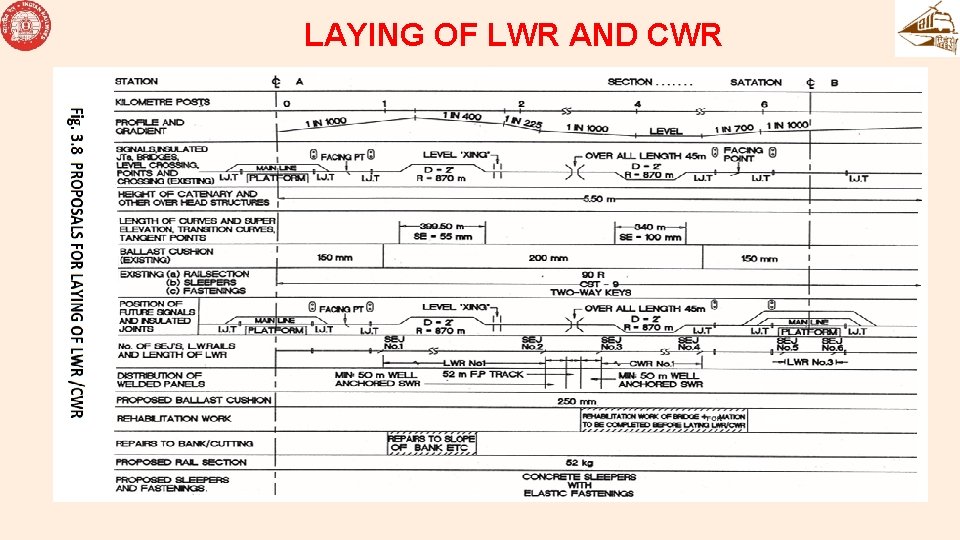
LAYING OF LWR AND CWR • (1) Survey: • (c) A detailed plan shall be made showing the exact locations of SEJs and of various other features mentioned in sub-Para (a) and (b) above. A sample of the detailed plan may be seen at Fig. 3. 8. The plans may be prepared to a horizontal scale of 1: 5000.
LAYING OF LWR AND CWR
LAYING OF LWR AND CWR • • • (2) Materials Required: Following materials are required for laying one LWR: (a) Four numbers of 4 metre or longer rail pieces of the same rail section as LWR (b) Two sets of SEJs with sleepers and fastenings (c) Adequate numbers of 1 metre long fishplates with special screw clamps/ joggled fishplates with slotted grooves & bolted clamps as in Fig. 3. 9, 3. 10, 3. 11 & 3. 12.
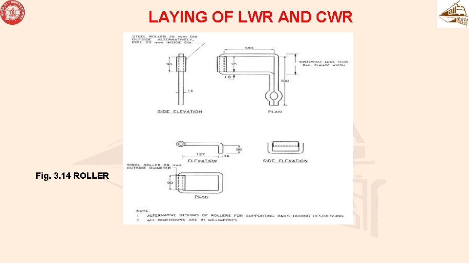
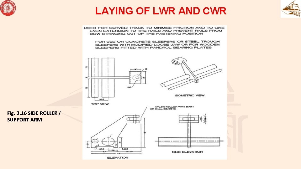
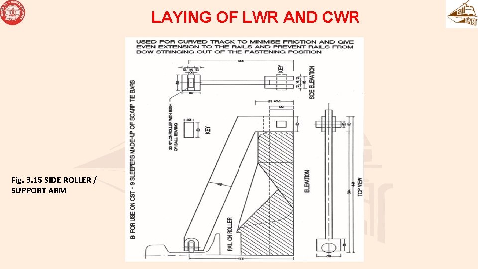
LAYING OF LWR AND CWR • Note: Slotted fishplates as in Fig. 3. 13 with fish-bolts may be used in exceptional cases. • (d) Rail closures of suitable sizes • (e) 1 metre and 10 cm straight edges • (f) Callipers and feeler gauges (2 mm to 0. 1 mm) • (g) Rail cutting equipment • (h) De-stressing equipment i. e. rollers, mechanical/hydraulic rail tensor, mallets and side rollers for curves, Fig. 3. 14, 3. 15 & 3. 16. • (i) Alumino-thermic welding equipment and consumable materials • (j) Equipment for protection of track.
LAYING OF LWR AND CWR • (2) Materials Required: • Following materials are required for laying one LWR: • (a) Four numbers of 4 metre or longer rail pieces of the same rail section as LWR • (b) Two sets of SEJs with sleepers and fastenings
LAYING OF LWR AND CWR • (2) Materials Required: • (c) Adequate numbers of 1 metre long fishplates with special screw clamps/ joggled fishplates with slotted grooves & bolted clamps as in Fig. 3. 9, 3. 10, 3. 11 & 3. 12. • Note: Slotted fishplates as in Fig. 3. 13 with fish-bolts may be used in exceptional cases.
LAYING OF LWR AND CWR Fig. 3. 9 - 1 m LONG SLOTTED FISH PLATE FOR CLAMPED JOINTS /SUPPORT ARM
LAYING OF LWR AND CWR Fig. 3. 10 SCREW CLAMP FOR FIXING 1 m LONG FISH PLATE
LAYING OF LWR AND CWR Fig. 3. 10 SCREW CLAMP FOR FIXING 1 m LONG FISH PLATE
LAYING OF LWR AND CWR Fig. 3. 11 M. S. CLAMP FOR FIXING 1 m LONG FISH PLATE
LAYING OF LWR AND CWR Fig. 3. 12 DETAILS OF JOGGLED FISH PLATE WITH CLAMP / SUPPORT ARM
LAYING OF LWR AND CWR • (2) Materials Required: • d) Rail closures of suitable sizes • (e) 1 metre and 10 cm straight edges • (f) Callipers and feeler gauges (2 mm to 0. 1 mm) • (g) Rail cutting equipment
LAYING OF LWR AND CWR • (2) Materials Required: • (h) De-stressing equipment i. e. rollers, mechanical/hydraulic rail tensor, mallets and side rollers for curves, Fig. 3. 14, 3. 15 & 3. 16. • (i) Alumino-thermic welding equipment and consumable materials • (j) Equipment for protection of track.
LAYING OF LWR AND CWR Fig. 3. 14 ROLLER
LAYING OF LWR AND CWR Fig. 3. 16 SIDE ROLLER / SUPPORT ARM
LAYING OF LWR AND CWR Fig. 3. 15 SIDE ROLLER / SUPPORT ARM
Welding of Rails to form LWR • (1) Rails shall normally be welded into sufficiently long panels of 10 to 20 rail lengths or more by flash butt welding, either in the welding depot or on cess or in-situ. The joints in between only shall be welded by Alumino-Thermic welding (SKV process)/flash butt welding (using mobile FBW plant). • (2) Before laying long welded panels and/or before welding of rails, two complete sets of SEJs, one at either end of the proposed LWR/CWR shall be inserted at pre-determined locations with gaps in mean position as per Para 338. Closure rails of suitable length (refer Para 340/341) shall be provided at LWR side/sides of SEJs to facilitate adjustment of gaps during de-stressing operation.
Welding of Rails to form LWR • (3) Laying of welded panels and/or welding of joints at site can be done at any time of the year. However, after welding into sufficiently long panels of about 1 km or longer, de-stressing as per Para 340 / 341 shall be undertaken as soon as possible. • (4) Under unavoidable circumstances where de-stressing could not be done soon after and not likely to be done within a reasonable period, a strict vigil shall be maintained on the prevailing rail temperatures, and if the rail temperature rises more than 20°C above the rail temperature at which welding of rails/laying of welded panels was done temporary destressing shall be undertaken at a rail temperature of 10°C below the maximum rail temperature likely to be attained until final de-stressing. If the rail temperature comes down appreciably, cold weather patrolling as per Para 1005(3) should be introduced. Final de-stressing shall be done after consolidation of track has been achieved.
Welding of Rails to form LWR • (5) Consolidation of track can be achieved by the following: • (a) For Existing track where maintenance activity involving disturbance to ballast compaction (tamping operation) has been undertaken. • (i) For the track structure consisting of concrete sleepers, passage of at least 50, 000 gross tonnes of traffic or a period of two days whichever is later. • (or) • (ii) At least one round of stabilisation by Dynamic Track Stabiliser (DTS).
Welding of Rails to form LWR • (5) Consolidation of track can be achieved by the following: • (b) For newly laid track (CTR/TSR) or freshly deep screened Track • Three rounds of packing, last two of which should be by on-track tamping machines • (6) Temporary speed restriction as indicated in Annexure-3/8 shall be imposed on the length of track where welded panels are joined by 1 m long fishplates with special screw clamps or joggled fishplates with slotted grooves & bolted clamps as in Fig. 3. 9, 3. 10, 3. 11 & 3. 12.
Gaps at SEJ • (1) (a) The thermal force in a LWR as shown in Para 335 is to be resisted by suitable track structure. Accordingly, the Gap at SEJ depends on following factors: • (i) Longitudinal Ballast Resistance of sleepers (taken as 13. 28 or 13. 74 kg / cm / rail per sleeper for PSC sleeper of density 1540 or 1660 per km respectively, which is indicative and can vary as per site conditions)
Gaps at SEJ • (ii) Area of rail section • (iii) Modulus of Elasticity (E) for rail steel • (iv) Coefficient of linear expansion (α) for rail steel • (v) Difference between the De-stressing temperature and prevailing rail temperature of LWR • (vi) Initial gap at SEJ at de-stressing temperature.
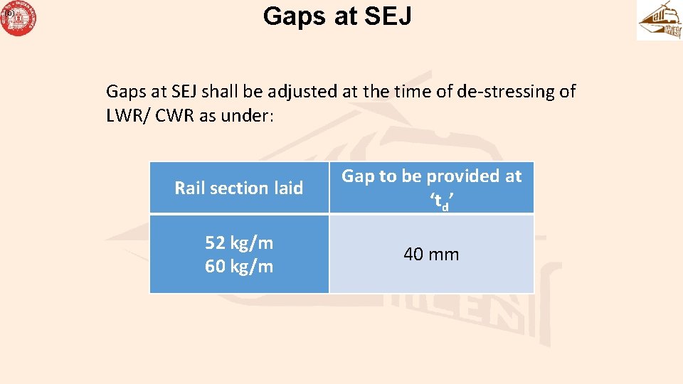
(b) Gaps at SEJ shall be adjusted at the time of de-stressing of LWR/ CWR as under: Rail section laid Gap to be provided at ‘td’ 52 kg/m 60 kg/m 40 mm
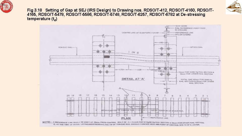
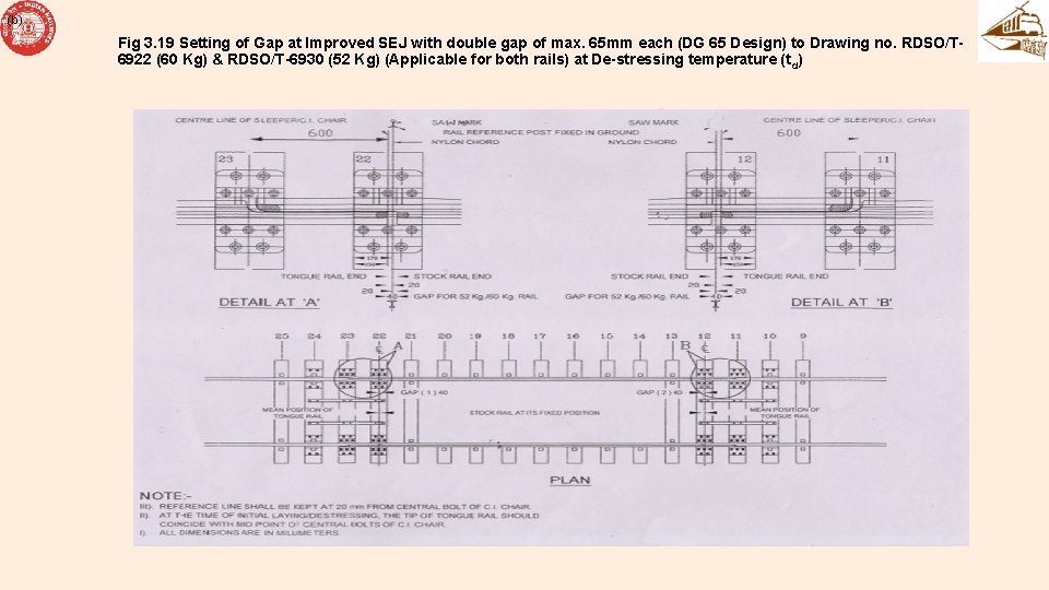
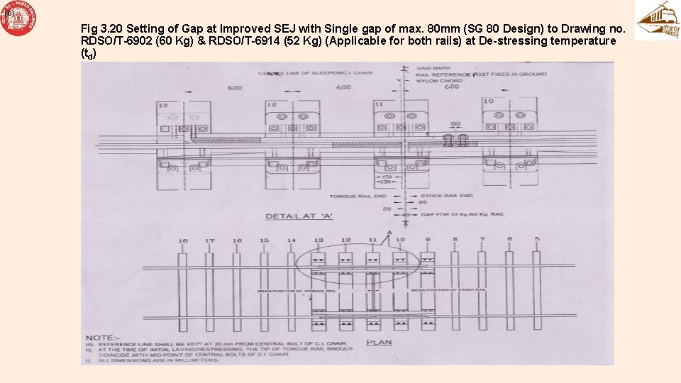
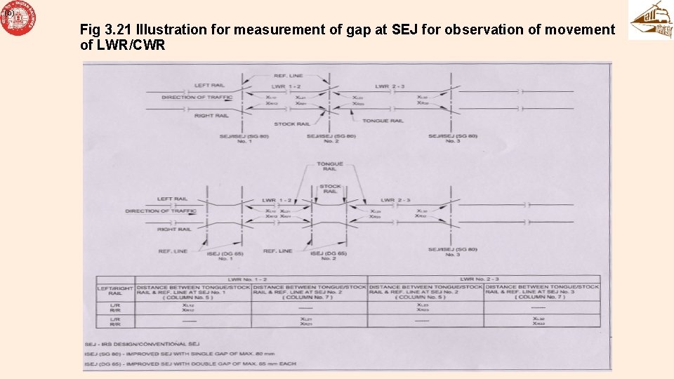
(b) Gaps at SEJ • (c) For Gaps at different types of SEJ and its laying and measurement, Fig No 3. 18, 3. 19, 3. 20, 3. 21 may be referred to:
(b) Fig 3. 18 Setting of Gap at SEJ (IRS Design) to Drawing nos. RDSO/T-412, RDSO/T-4160, RDSO/T 4165, RDSO/T-5478, RDSO/T-5586, RDSO/T-5748, RDSO/T-6257, RDSO/T-6782 at De-stressing temperature (td)
(b) Fig 3. 19 Setting of Gap at Improved SEJ with double gap of max. 65 mm each (DG 65 Design) to Drawing no. RDSO/T 6922 (60 Kg) & RDSO/T-6930 (52 Kg) (Applicable for both rails) at De-stressing temperature (t d)
(b) Fig 3. 20 Setting of Gap at Improved SEJ with Single gap of max. 80 mm (SG 80 Design) to Drawing no. RDSO/T-6902 (60 Kg) & RDSO/T-6914 (52 Kg) (Applicable for both rails) at De-stressing temperature (td)
(b) Fig 3. 21 Illustration for measurement of gap at SEJ for observation of movement of LWR/CWR
THANKS