GAS INJECTION TECHNOLOGY The gas injection technique GIT
 is a special injection molding method.")


")


 the electrical system, b) the")


 Conventional Injection Moulding Process b) Gas-Assisted Injection Moulding Process a)The evolution of pressure")
")
")

 In the case of the standard GIT, the mold is")


- Slides: 49
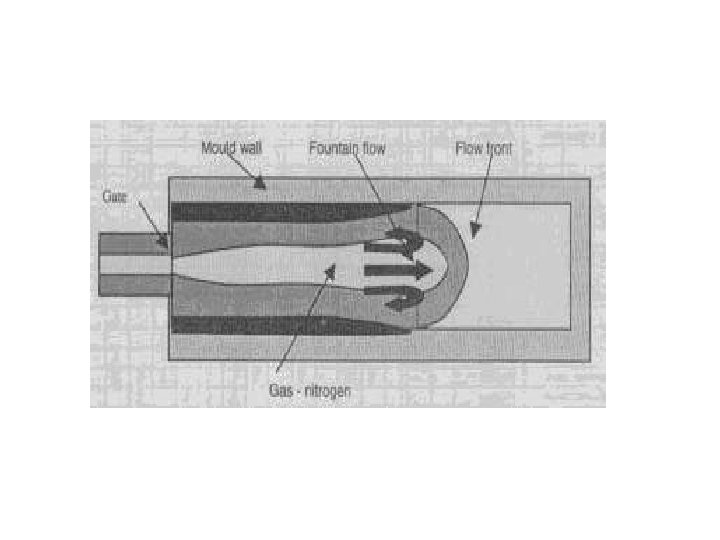
GAS INJECTION TECHNOLOGY The gas injection technique (GIT) is a special injection molding method. After the actual injection molding operation a permanent cavity is created in the molding as a second step by means of an inert compressed gas (nitrogen). The plastic is pressed against the mold wall by maintaining the gas pressure during the solidification process, thus defining the external contour of the component.
Need for Gas – Assisted Injection Moulding: ü The production of thick-walled mouldings from thermoplastics in the conventional injection moulding processes causes difficulties. ü The sink marks that occur due to volume contraction of the plastic cannot be completely compensated by the subsequent inflow of melt. ü Processes such as low-pressure structural foam moulding, gas counter pressure injection moulding, and co injection moulding were developed to avoid sink marks that occurred during the production of thick – walled moldings form thermoplastics ü During gas-assisted injection moulding, a gas is injected into the interior of the melt with the objective of counteracting volume contraction during cooling by means of the internal gas pressure inside the moulding.
Gas Assisted Injection Moulding Processes: There are two different methods of gas generation known: A) Discontinuous Pressure Generation B) Continuous Pressure Generation
Discontinuous Pressure Generation Ø A cylinder is filled with nitrogen; then the gas is compressed by a pressure intensifying system. Ø As soon as the pressure has reached the preset pressure, the gas is injected. A specific feature of this process is the volumetric control of the gas before compression. Ø For every injection cycle, the pressure has to be built up before the gas can be injected, which means there is a minimum recovery time required between two injections. Ø High gas pressures as holding pressures normally cannot be maintained during the cooling period.
Continuous Pressure Generation ü The continuous pressure generation functions with gas compressors which bring up the nitrogen pressure to a determined pressure level that is, 30 MPa at the injection point, the pressure is reduced by means of suitable valves. ü The process is characterized by pressure control. ü A basic advantage of the continuous pressure control is that even high gas pressures can be maintained for almost the complete cooling time. ü The gas injection at several injection points or for different injection moulding machines can be preformed easily by using only one pressure – generating system.
materials ü ü ü ü ü Polypropylene Acrylonitrile – Butadiene - Styrene polymer (ABS) Poly. Ethylene (PE) Poly. Propylene (PP) Poly. Styrene (PS) Styrene - Acrylonitrile copolymer (SAN) Poly. Phneyleneoxide (PPO) modified Polycarbonate(PC) Poly. Butylene Terephthalate (PBT) Blends of Poly. Carbonate (PC) – Poly. Butylene Terephtalate (PBT) ü Thermoplastic Poly. Urethane (TPU) ü Thermoplatic elastomer (TPE)
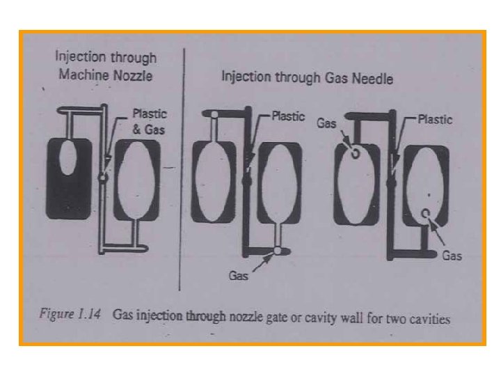
Gas Assisted Injection v Injection through the machine nozzle v Injection directly into the mould Advantages v No Sink marks v No built in stresses v Shorter cycle time v Reduction in weight
GAIM Model
Gas assisted injection moulding system Gas-assisted injection moulding: a) the electrical system, b) the hydraulic system, c) the control panel, d) the gas cylinder.
Gas injection into product
Gas Assisted Through The Nozzle: Ø Gas injection through the nozzle can be achieved generally for axisymmetric mouldings requiring no changes to the existing mould. Ø Gas injection through the nozzle is also favorable when the hole in the moulding, formed by the gas injection, cannot be accepted and thus must be sealed with plastic. Ø This is achieved by releasing the gas pressure by the sprue break at the end of the gas holding time, and subsequently injecting a finite amount of melt through the sprue. Ø Gas injection can also be done directly into the sprue. Ø An unbalanced filling of the cavities with plastic produces an uneven gas penetration.
Gas Injection Into The Mould: Ø Gas injection separate from melt injection. Ø The selected location for gas injection offers design flexibility for the manufacture of products with a high quality level. Ø Gas is injected either directly into the cavity or into the runner. Ø Gas injection modules, which are placed directly in the mould, may be stationary or retractable. Ø Stationary injection modules are fixed in the mould. Ø This type of module is used when the installation direction coincides with the demolding direction of the product. Ø Retractable injection modules have to be withdrawn before the mould opens.
SCHEMATIC OF GAS INJECTION INTO THE CAVITY USING STATIONARY AND RETRACTABLE MODULES.
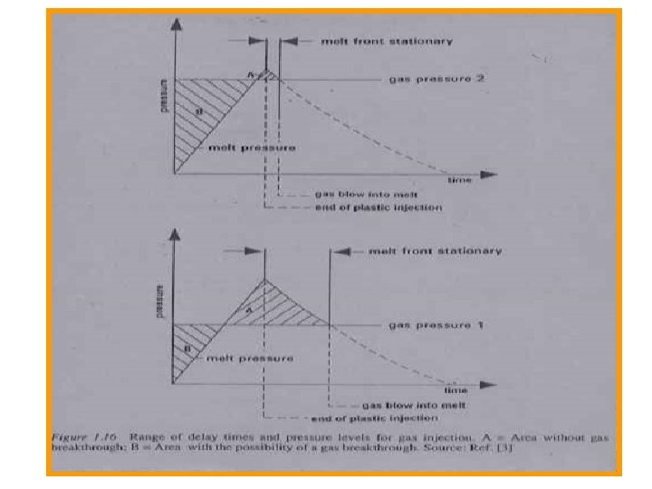
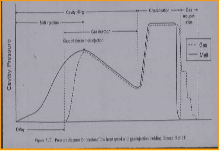
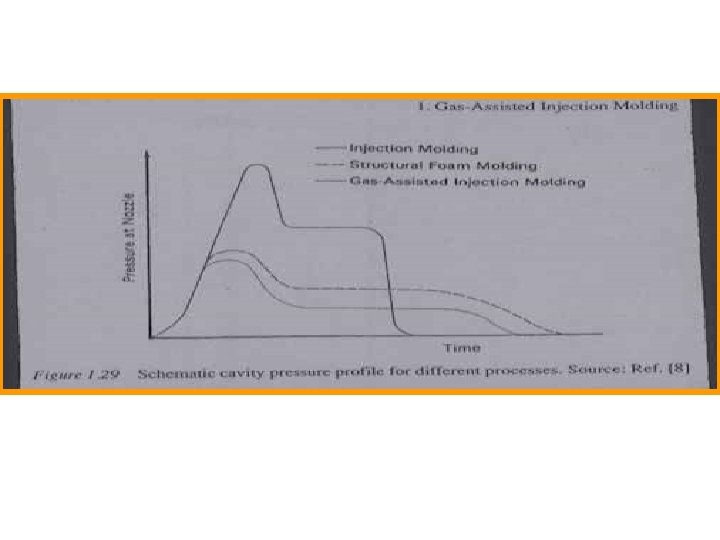
Processing Technology Injection Sequence • Nitrogen is used, as it is an inert gas. • A simultaneous injection of plastic and gas is not possible, as the gas would immediately break through the melt front. • The timing of gas injection and the gas pressure are of great importance to produce useful moulding. • Pressure versus time plots with and without breakthrough (fig) • As long as the gas pressure is greater than the melt pressure in the unfilled mould, the gas will advance and eventually break through the melt. • The gas can be injected only when the gas pressure is as high as the melt temperature. • A typical pressure diagram of mould filling ( fig).
viscosity Ø The gas viscosity is very low in comparison on the polymer viscosity. Ø When injecting gas into a flat panel the gas does not penetrate evenly, but always takes the easiest way to the end of the flow path. Ø This effect, called “Fingering” may cause flow instability.
Wall Thickness: ØFor rod-shaped mouldings, a regular wall thickness distribution is required. ØIt was found that the typical parameters such as melt temperature, mould temperature, and melt filling time have only a small influence on polymer wallthickness.
Shrinkage: ØThe shrinkage or injection mouldings depends on the polymer, filler, shape of the moulding, and processing conditions. ØTwo processing parameters that have a great influence on shrinkage are gas pressure level and gas pressure time. ØHigher gas pressure level and longer gas pressure time reduce the shrinkage of the mouldings. .
PROCESSING The processing process in gas injection molding takes place as follows: Øclosing the mold Øinjecting the plastic Øgas injection in the plastic melt Ømaintenance of the gas pressure during solidification Øreduction of gas pressure Øopening the mold Øremoval of part from mold
Injection sequence for gas injection into mould.
STAGE –I : FILLING STAGE 1 : Cycle begins 1: 2 : Resin injection stage 2 : Resin injection ends 3 : Delay time 3 -4 : Gas injection begins 4 : Cavity filling completed STAGE – 2: POST FILLING 4: 5 : Gas pressure held 5 : Gas pressure released 6 : Mould opens STAGE – 3: MOULD OPENING STAGE The machine cycle for a typical gas- assisted injection moulding process. Resininjection time is between points 1 & 2, the timer starts gas injection ar point 3, the fill time is between points 1 & 4, and gas injection time is from point 3 to point 5.
a) Conventional Injection Moulding Process b) Gas-Assisted Injection Moulding Process a)The evolution of pressure distribution for the conventional injection moulding process. b) The evolution of pressure distribution for the gas – assisted injection moulding process. The lower but more uniform pressure distribution in the case of gas – assisted injection moulding.
Inadequate pre-filling with the standard GIT (gas breakthrough)
Excessive pre-filling with the standard GIT (material accumulation, sink)
As a special feature in relation to conventional injection molding, a permanent cavity is created in a molding by means of an inert compressed gas (nitrogen) after injection of the melt. A basic distinction is made here between two methods: v The blow-up technique (standard GIT) and v The blow-out technique (secondary cavity method) or counter flow technique.
Blow-up method (standard GIT) In the case of the standard GIT, the mold is first partially filled with melt: then this melt volume "is blown up" with the help of the process gas and the molding is shaped completely in this way. Through the gas pressure inside the molding the melt is pressed against the external walls of the mold such that a hollow body is formed.
Blow-out method In the blow-out and/or counter flow technique the cavity is first completely filled with melt and then the still plastic core is "blown out" again. The melt is blown out in an overflow cavity that is additionally inserted in the mold or by blowing back into the injection cylinder. The method to be applied is primarily determined by the design of the molding. Furthermore, the patent situation also has to be taken into account in the selection of the method
ü The delay time until the changeover from melt injection to gas injection must be kept as short as possible in the standard GIT, otherwise so-called switchover markings occur due to melt stagnation. ü The blow-out technique offers advantages here since the molding surface is shaped cleanly through the initially complete filling of the cavity. ü The subsequent injection of the gas no longer influences the molding surface. ü The residual wall thicknesses that result tend to be somewhat larger than in the standard GIT. ü A disadvantage is that the overflow cavity must be cut off if it is not blown back into the machine.
ü The method applied in the end is essentially determined on the basis of the molding geometry. ü The standard GIT is suitable for rod-shaped moldings while partial material accumulations can also be blown out by means of the blow-out technique. ü The patent situation has to be considered as well when making the choice.
Advantages that result from such GIT applications in the production process are; Ø rod-shaped moldings Ø greater design freedom (thick-walled, rod-shaped parts possible) Ø high degree of rigidity due to larger closed cross-section profiles Ø reduction of sink marks Ø uniform shrinkage and thus less distortion Ø shorter cycle times as compared to thick-walled compact parts Ø with rod-shaped parts weight savings of up to approx. 50% Ø with large-area parts less locking force because the required filling pressure is less and the pressure distribution in the hold period is more even
Component design The following design instructions must be kept in mind in connection with the GIT: Ø provide deflections with large radii as far as possible Ø avoid process- or geometry-related material accumulations Ø optimize cross-sections for rod-shaped moldings (no sharp edges, instead provide edges with radii, round cross-section profile as far as possible) Ø match length and cross-section Ø favorable design of gas ducts Ø arrangement of ribs and gas ducts.
Design Guidelines: ü Design guidelines in general need to be based on v Understanding of the gas flow, v How to achieve a gas penetration in the required areas. Rod – Shaped Mouldings: ü Rod-Shaped mouldings forming a ring are more difficult to inject because of the weld line area without gas. ü A reduction of wall thickness in the expected area of the weld line is useful war to balance gas distribution.
Design instructions for GIT: cross-section design for rod-shaped moldings
Gas Channels Gas channels are needed to control the gas flow and to keep the gas out of the thin-walled areas. The following conditions have to be met: Ø The difference in wall thickness between the channel and the basic wall must be large enough to contain the gas flow in the channel. Ø The basic wall itself should not be too thick to avoid gas penetration into thicker areas. Ø The basic wall thickness should not be so thin that air is trapped in central areas because of preferred gas flow in the thicker gas channels. Ø Preferred wall thickness of panel-shaped mouldings should be in the range of 2. 5 mm to 3. 5 mm, but not more than 4. 0 mm.
ü When the basic wall thickness is above the recommended values and a reduction is not possible, a reduction of wall thickness around the gas channel is helpful to keep the gas inside the gas channel areas. ü Even deep and thick ribs can be moulded without any sink marks. Gas Penetration along Surfaces Gas penetration into wall next to gas channel
Corners and Wall Thickness Variations ü The direction of the gas flow is affected by the shape of the moulding since the gas takes the path of least resistance. ü Sharp corners create thin wall regions ü Rounded edges provide a more uniform wall thickness distribution.
Design instructions for GIT: avoidance of material accumulations due to overflow
Design instructions for GIT: coordination of cross-section dimensions / minimum lengths
Design instructions for GIT: design of gas duct geometries
Design instructions for GIT: arrangement of ribs and gas ducts
Moulding technology MOULD DESIGN • Cavity pressures in gas-assisted molding are lower than those of conventional injection mouldings. • For rod shaped mouldings, pressures are even below of structural foam mouldings. • Normally cavity pressures between 5 and 20 Mpa (700 and 3000 psi) must be expected.
Undercuts • When Undercuts of the mouldings can be eliminated by means of gas assistance, no side cover actions in the mould are needed. Elimination of Undercuts by means of Gas - Assisted Injection Mouldings
Multicavity Moulds Ø First the cavities are filled with plastic up to a predetermined level, that is 70% or 80% before the gas injection starts. Ø A balanced filling of all cavities is an important condition in achieving on identical gas penetration in all cavities. Ø Good balancing of runners and gates is essential. Ø For more than two cavities, direct gas injection into the runners or the cavities is recommended Ø Cooling channels for multi cavity moulds are to be provided symmetrically. Ø Sequential cooling or two or more cavities by connecting cooling channels gives poor reliability in production, as the gas reacts to even minor temperature differences between the cavities. Ø Water supplies should be separate for each cavity.
End Use Products Automotive Bumper Fascia Plastic Lawn Chair Telivision Cabinet Double Basin Wash Tub