Injection molding Injection Moulding is a manufacturing technique


 • The cycle is completed when the mold opens and the part")


, Injection molding press, Injection mold (Hot runner,")

 coming")


 Shot size too small (b) Material melt temperature")
 Shot size too small (b) Injection pressure too")
 Purging compound left in barrel (b) Mold temperature too")
- Slides: 37
Injection molding • Injection Moulding is a manufacturing technique for making parts from plastic material. Molten plastic is injected at high pressure into a mould, which is the inverse of the desired shape. The mould is made by a mouldmaker (or toolmaker) from metal, usually either steel or aluminium, and precision-machined to form the features of the desired part. Injection moulding is very widely used for manufacturing a variety of parts, from the smallest component to entire body panels of cars. It is the most common method of production, with some commonly made items including bottle caps and outdoor furniture.
Contents • 1 Types of Injection Molding • 2 Injection molding equipment – 2. 1 Injection molding machine • 2. 1. 1 Horizontal or vertical machines • 2. 1. 2 Clamping unit – 2. 2 Injection mold • 3 Injection process – 3. 1 Injection Molding Cycle – 3. 2 Molding trial – 3. 3 Molding defects
Types of injection molding – Types of injection molding • • Reaction injection molding Liquid injection molding Gas assist injection molding Co-injection molding 2 -Shot Injection Molding Fusible core injection molding Rapid injection molding
Injection molding equipment • Injection molding machines, also known as presses, hold the molds in which the components are shaped. Presses are rated by tonnage, which expresses the amount of clamping force that the machine can generate. This pressure keeps the mold closed during the injection process. Tonnage can vary from less than 5 tons to 6000 tons, with the higher figures used in comparatively few manufacturing operations. • Horizontal or vertical machines • Injection molding machines can fasten the molds in either a horizontal or vertical position. The majority is horizontally oriented but vertical machines are used in some niche applications such as insert molding, allowing the machine to take advantage of gravity.
Clamping unit • Machines are classified primarily by the type of driving systems they use: hydraulic, electric, or hybrid. Hydraulic presses have historically been the only option available to molders until Nissei introduced the first all electric machine in 1983. The electric press, also known as Electric Machine Technology (EMT), reduces operation costs by cutting energy consumption and also addresses some of the environmental concerns surrounding the hydraulic press. Electric presses have been shown to be quieter, faster, and have a higher accuracy, however the machines are more expensive. Hybrid injection molding machines take advantage of the best features of both hydraulic and electric systems. Hydraulic machines are the predominant type in most of the world, with the exception of Japan. • Injection mold • Considerable thought is put into the design of moulded parts and their moulds, to ensure that the parts will not be trapped in the mould, that the moulds can be completely filled before the molten resin solidifies, to compensate for material shrinkage, and to minimize imperfections in the parts, which can occur due to peculiarities of the process
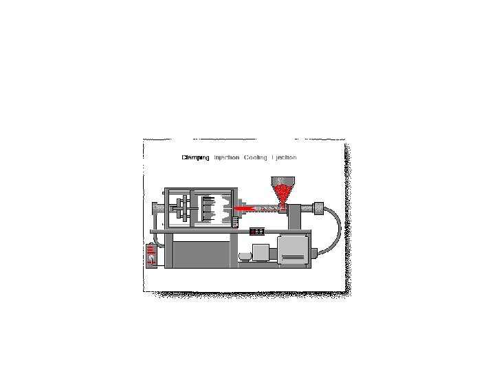
Injection process • Injection Molding Cycle • The basic injection cycle is as follows: Mold close injection carriage forward - inject plastic - metering carriage retract - mold open - eject part(s) • The molds are closed shut by hydraulics or electric, and the heated plastic is forced by the pressure of the injection screw to take the shape of the mold. Some machines are run by electric motors instead of hydraulics or a combination of both. The water-cooling channels then assist in cooling the mold and the heated plastic solidifies into the part. Improper cooling can result in distorted molding or one that is burnt. The cycle is completed when the mold opens and the part is ejected with the assistance of ejector pins within the mold.
• Mold close • The molds are closed shut by hydraulics or electric, and the heated plastic is forced by the pressure of the injection screw to take the shape of the mold. Some machines are run by electric motors instead of hydraulics or a combination of both. The water-cooling channels then assist in cooling the mold and the heated plastic solidifies into the part. Improper cooling can result in distorted molding or one that is burnt. • Mold safety is low speed and low pressure mold closing. It usually begins just before the leader pins of the mold and must be set properly to prevent accidental mold damage. When the mold halves touch clamp tonnage is built.
Inject plastic • Molten plastic material is injected into the mold. The material travels into the mold via the sprue bushing, then the runner system delivers the material to the gate. The gate directs the material into the mold cavity to form the desired part. This injection usually occurs under velocity control. When the part is nearly full, injection control is switched from velocity control to pressure control. This is referred to as the pack/hold phase of the cycle. Pressure must be maintained on the material until the gate solidifies to prevent material from flowing back out of the cavity. Cooling time is dependent primarily on the wall thickness of the part. During the cooling portion of the cycle after the gate has solidified, plastication takes place. Plastication is the process of melting material and preparing the next shot. The material begins in the hopper and enters the barrel through the feed throat. The feed throat must be cooled to prevent plastic pellets from fusing together from the barrel heat. The barrel contains a screw that primarily uses shear to melt the pellets and consists of three sections. The first section is the feed section which conveys the pellets forward and allows barrel heat to soften the pellets. The flight depth is uniform and deepest in this section. The next section is the transition section and is responsible for melting the material through shear. The flight depth continuously decreases in this section, compressing the material. The final section is the metering section which features a shallow flight depth, improves the melt quality and color dispersion. At the front of the screw is the non-return valve which allows the screw to act as both an extruder and a plunger. When the screw is moving backwards to build a shot, the nonreturn assembly allows material to flow in front of the screw creating a melt pool or shot. During injection, the non-return assembly prevents the shot from flowing back into the screw sections
Mold open • Once the shot has been built and the cooling time has timed out, the mold opens. Mold opening must occur slow-fastslow. The mold must be opened slowly to release the vacuum that is caused by the injection molding process and prevent the part from staying on the stationary mold half. This is undesirable because the ejection system is on the moving mold half. Then the mold is opened as far as needed, if robots are not being used, the mold only has to open far enough for the part to be removed. A slowdown near the end of travel must be utilized to compensate for the momentum of the mold. Without slowing down the machine cannot maintain accurate positions and may slam to a stop damaging the machine. Once the mold is open, the ejector pins are moved forward, ejecting the part.
Shot built • The resin, or raw material for injection molding, is usually in pellet or granule form, and is melted by heat and shearing forces shortly before being injected into the mold. Resin pellets are poured into the feed hopper, a large open bottomed container, which feeds the granules down to the screw. The screw is rotated by a motor, feeding pellets up the screw's grooves. The depth of the screw flights decreases towards the end of the screw nearest the mold, compressing the heated plastic. As the screw rotates, the pellets are moved forward in the screw and they undergo extreme pressure and friction which generates most of the heat needed to melt the pellets. Heaters on either side of the screw assist in the heating and temperature control during the melting process
Eject part(s) • The cycle is completed when the mold opens and the part is ejected with the assistance of ejector pins within the mold. When the ejector pins retract, all criteria for a molding cycle have been met and the next cycle can begin. • The channels through which the plastic flows toward the chamber will also solidify, forming an attached frame. This frame is composed of the sprue, which is the main channel from the reservoir of molten resin, parallel with the direction of draw, and runners, which are perpendicular to the direction of draw, and are used to convey molten resin to the gate(s), or point(s) of injection. The sprue and runner system can be cut or twisted off and recycled, sometimes being granulated next to the mold machine. Some molds are designed so that the part is automatically stripped through action of the mold.
• Clamping Area The largest rated molding area an injection press can hold closed under full molding pressure.
Molding trial • When filling a new or unfamiliar mold for the first time, where shot size for that mold is unknown, a technician/tool setter usually starts with a small shot weight and fills gradually until the mold is 95 to 99% full. Once this is achieved a small amount of holding pressure will be applied and holding time increased until gate freeze off has occurred, then holding pressure is increased until the parts are free of sinks and part weight has been achieved. Once the parts are good enough and have passed any specific criteria, a setting sheet is produced for people to follow in the future.
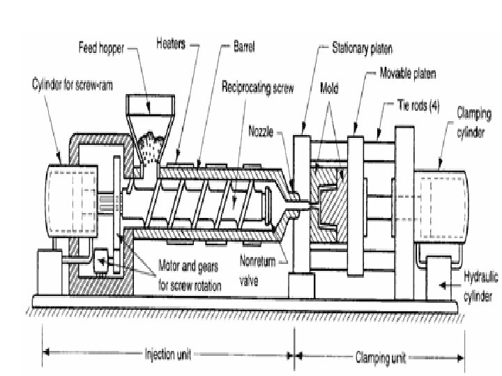
Injection molding machines consist of two basic parts, an injection unit and a clamping unit. Injection molding machines differ in both injection unit and clamping unit. The name of the injection molding machine is generally based on the type of injection unit used.
• 1 Types of injection molding machines – 1. 1 Hydraulic – 1. 2 Electric – 1. 3 Hybrid • 2 Injection unit – – – 2. 1 Feed hopper 2. 2 Injection ram 2. 3 Injection screw 2. 4 Barrel 2. 5 Injection cylinder • 3 Clamping unit – – 3. 1 Injection mold 3. 2 Injection platens 3. 3 Clamping cylinder 3. 4 Tie Bar
Types of injection molding machines • Machines are classified primarily by the type of driving systems they use: hydraulic, electric, or hybrid. • Hydraulic presses have historically been the only option available to molders until introduced the first all-electric injection molding machine in 1983. The electric press, also known as Electric Machine Technology (EMT), reduces operation costs by cutting energy consumption and also addresses some of the environmental concerns surrounding the hydraulic press. • Electric presses have been shown to be quieter, faster, and have a higher accuracy, however the machines are more expensive. • Hybrid injection molding machines take advantage of the best features of both hydraulic and electric systems. Hydraulic machines are the predominant type in most of the world, with the exception of Japan.
Injection unit • The injection unit melts the polymer resin and injects the polymer melt into the mold. The unit may be: ram fed or screw fed. • Feed hopper • The container holding a supply molding material to be fed to the screw. The hopper located over the barrel and the feed throat connects them. • Injection ram • The ram or screw that applies pressure on the molten plastic material to force it into the mold cavities.
• Injection screw • The reciprocating-screw machine is the most common. This design uses the same barrel for melting and injection of plastic. • The alternative unit involves the use of separate barrels for plasticizing and injecting the polymer. This type is called a screw-preplasticizer machine or two-stage machine. Plastic pellets are fed from a hopper into the first stage, which uses a screw to drive the polymer forward and melt it. This barrel feeds a second barrel, which uses a plunger to inject the melt into the mold. Older machines used one plungerdriven barrel to melt and inject the plastic. These machines are referred to as plunger-type injection molding machines.
• Barrel is a major part that melts resins transmitted from hopper through screws and structured in a way that can heat up resins to the proper temperature. A band heater, which can control temper atures in five sections, is attached outside the barrel. Melted resins are supplied to the mold passing through barrel head, shot-off nozzle, and onetouch nozzle. • Injection cylinder • Hydraulic motor located inside bearing box, which is connected to injection cylinder load, rotates screw, and the melted resins are measures at the nose of screw. There are many types of injection cylinders that supply necessary power to inject resins according to the characteristics of resins and product types at appropriate speed and pressure. This model employs the double cylinder type. Injection cylinder is composed of cylinder body, piston, and piston load.
Clamping unit • The clamping unit holds the mold together, opens and closes it automatically, and ejects the finished part. The mechanism may be of several designs, either mechanical, hydraulic or hydromechanical. • [Injection mold • There are two main types of injection molds: cold runner (two plate and three plate designs) and hot runner – the more common of the runnerless molds. • Injection platens • Steel plates on a molding machine to which the mold is attached. Generally, two platens are used; one being stationary and the other moveable, actuated hydraulically to open and close the mold. It actually provide place to mount the mould. It contains threaded holes on which mould can be mounted using clamps
• Clamping cylinder • A device that actuates the chuck through the aid of pneumatic or hydraulic energy. • Tie Bar • Tie bars support clamping power, and 4 tie bars are located between the fixing platen and the support platen
• Equipment: Injection molding machine(Vertical, Horizontal), Injection molding press, Injection mold (Hot runner, Cold runner), Injection unit (Injection ram, Injection screw), Clamping unit (Toggle , Hydraulic, Hydromechanical), Plunger injection molding, Injection molding machine manufacturers, Types of injection molding machines • Terms: Injection pressure, Injection rate, Clamping pressure
• Back pressure The hydraulic pressure developed in the injection cylinder of an injection molding machine during plasticating to cause more shear heating and mixing of the material. The pressure generated on the plastic as the screw rotates and pumps the plastic into the front of the barrel. • Clamping tonnage Rated clamping capacity of an injection molding machine • Cycle time The time elapsing between a particular point in one cycle or production and the same point in the next cycle. The optimum processing cycle calls for a balance between the filling, cooling, and holding requirements set forth by the material and the part. • Machine shot capacity Generally based on polystyrene. This is the maximum weight of plastic that can be displaced or injected by a single stroke.
• Injection rate - It is the flow rate of melt (cc/sec) coming out of nozzle. Melt comes out in the form of jet. Then it spreads inside the mould in shape of the space between the core and cavity. • Molding cycle The period of time required to complete the molding of a part. • In injection molding, the cycle begins when the mold closes and ends with the opening of the mold and ejection of the molded part. The events that make up a complete operating sequence of the machine to mold a part. Molding Pressure The pressure applied to the ram of an injection machine or press to force the softened plastic completely to fill the mold cavities.
Processing troubleshooting • Black Specks A specific kind of inclusion/contamination often associated with degraded materials Blister An imperfection, a rounded elevation of the surface of the plastic, with boundaries that may be more or less sharply defined. Often caused by trapped gas from moisture, air, degraded polymer or degraded additives. • Blisters Bubbles on the surface of the part caused by trapped gases
• Blush Discoloration on the part at the gates or other obstructions in the flow path. Bubble A spherical, internal void; globule of air or other gas trapped within a molded plastic product. Differs from a blister in that the bubble is contained within the part with no surface protrusion. Also differs from a void, which is developed by formation of a second vacuum during cooling. Burn marks Small black sections on the part surface caused by burning plastic or ignited air. Burrs Tiny slivers of metal that have been raised up on a corner or edge of steel. They may cause difficulty in part ejection, and thus damage the mold.
• Clear spots Transparent imperfections in the part. • Contamination Visible defects caused by a foreign substance. • Crazing An undesirable defect in plastics articles characterized by distinct surface cracks or minute frost-like, internal cracks, resulting from stresses within the article which exceed the tensile strength of the plastic. • Delamination The surface of the finished part separates or appears to be composed of layers of solidified resins. Strata or fish scale-type appearance where the layers may be separated. • Discoloration A general change in the original color of the plastic material.
• Fish eye Small globular mass that has not blended completely into the surrounding material resulting as a fault in film, sheet, or molded part. • Flash The thin, surplus of material which if forced into crevices between mating mold surfaces during a molding operation remains attached to the molded article. • Flow line The area of a molded part where multiple masses of plastic meet and weld together during molding. Ripples or lines on the part surface that follow the direction of the melt into the cavity.
• Gate Blush A blemish or disturbance in the gate area of an injection molded article. • Gate mark Blemish on the molded part left by the mold gate. Haze The cloudy or turbid aspect or appearance of an otherwise transparent specimen caused by light scattered from within the specimen or from its surfaces. ASTM D 1003; haze is the percentage of transmitted light that, in passing through the specimen, deviates from the incident beam through forward scatter more than 2. 5 degrees on average. • Jetting Instability cause by improper gate design and too high flow rate. Result is work tracks on the plastic part. Crooked or snakelike patterns on the part surface. • Meld lines The marks visible on a finished part made by two flow fronts, traveling parallel to each other, meeting during molding. Areas in the part where two different fronts of molten plastic have come together • Melt instability An instability in the melt flow through a mold or die that causes irregularities in the finished part.
• Molding flash is excess material attached to a molded product, which must usually be removed. This is typically caused by leakage of the material between the two surfaces of a mold. Molding flash is seen when the optimized parameter on cull height is not calibrated. Parting Line The mark on a molded article caused by flow of material into the crevices between mold parts. Pitting Spot corrosion that is caused by chemical or galvanic effects. • Short Shot In injection molding, failure to fill the mold completely. • Stress-Crack External or internal cracks in a plastic caused by tensile stresses less than that of its short-time mechanical strength. • Striations Marks evident on the molded part surfaces that indicate resin flow directions or impingement
• Stringing This effect occurs between the finished part and the sprue or gate in hot tip molds. When the mold opens, the resin in this area has not cooled sufficiently. • Surging An unstable pressure build-up leading to variable output and wavy extrudate surface. Surging may cause flow to stop for a moment at intervals. • Voids Pockets of unfilled space or vacuum in a molded part generally caused by shrinkage during cooling. Bubbles of air or other gases trapped in the part. • Warpage The distortion caused by non-uniform shrinkage within a part. This non-uniform shrinkage is caused by some kind of stress induced during filling, packing, or cooling. Warp is a complex phenomenon and is often caused by the combination of many forces, a few of which are dominant. Do not confuse with distortion; a physical deformation of the article.
• Warping A change in the shape of the part after ejection. • Weld lines The marks visible on a finished part made by two flow fronts, traveling in opposite directions, meeting during molding. Areas in the part where two different fronts of molten plastic have come together at a "meeting" angle less than 135°F. • Wisps These are similar to stringing but smaller in size. These may also occur as slight flashing when the mold is overpacked, forced open slightly or due to mold parting line wear or misalignment.
• 1. Short shots (a) Shot size too small (b) Material melt temperature too low (c) Injection pressure too low (d) Injection velocity too slow (e) Mold temperature too low (f) Sprue, runners, and/or gates too small 2. Dull streaks, flow lines (a) Melt temperature too low (b) Runners too small (c) Inadequate cold slug well (d) Mold temperature too low (e)Injection speed to slow
• 3. Sink marks (a) Shot size too small (b) Injection pressure too low (c) Hold pressure too low (d) Hold time too short (e) Cooling time too short (f) Mold temperature too high 4. Warpage (a) Mold temperature too high (b) Melt temperature too high (c) Insufficient hold time (d) Injection speed too fast (e) Insufficient cooling time 5. Poor knit lines (a) Mold temperature too cold (b) Injection speed too slow (c) Melt temperature too low (d) Poor venting
• 6. Lamination (a) Purging compound left in barrel (b) Mold temperature too low (c) Melt temperature too low (d) Injection speed too fast (e) Gate size too small 7. Blush marks at gate (a) Mold temperature too cold (b) Injection speed too fast (c) Sprue and nozzle diameter too small (d) Insufficient cold slug well (e) Moisture in compound 8. Burn streaks in center of sprue (a) Front zone temperature too high (b) Screw speed too high (c) Excessive back pressure (d) Compression ratio too high 9. Silver streaks on part (a) Injection pressure too high (b) Injection speed too fast (c) Melt temperature too high (d) Poor venting 10. Burn streaks at gate (a) Injection speed too fast