2 1 Laying Inspection Maintenance of fan shaped


 Sl. N")


 has Recommended following SEAs for different speeds")


 Speed due to non-provision")


 1 in 8. 5 - 52")

- Slides: 129
2. 1 Laying, Inspection& Maintenance of fan shaped turnouts, Spring setting device, Maintenance of turn in curves. 2. 2 Speed Potential of Turnouts, Permissible Speed on Turnouts, and Strengthening of loop lines for 30 kmph/ 50 kmph. Periods 3
Turnouts on Concrete Sleepers • Breakthrough § In 1990 – Development of Fan-Shaped Layout • Features § Inter changability for LH as well as RH Turnouts § Lead portion Sleeper spacing § More on outer side than on inner side measured along gauge faces of Main Line rails § Resemble fan “Fan Shaped Layout”
Salient Features of Fan Shaped Layout • • Gauge - 1673 mm SRJ to TNC - (Distance same as that of IRS Layout) Joints - Welded/Machined Approach Sleepers • Special sleepers on Approach (2750) and Exit (2550); • One sleeper for Signal fitting (Lock Bar) 60 S (2750) • Total No. of sleepers • 1 in 12 96 - 83 + ((3 x 4) + 1) • 1 in 8. 5 67 - 54 + ((3 x 4) + 1) • 1 in 16 114 - 101 + ((3 x 4) + 1)
Salient Features of Fan Shaped Layout • Fittings § Switch Portion§ Dowel & Screw system with rubber sole pad and spring washer. § Lead Portion§ ERC with GR Pad and Liner § Crossing Portion§ ERC with GR Pad and Liner
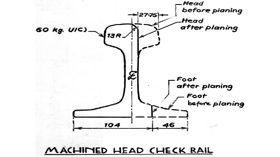
Salient Features of Fan Shaped Layout • Crossing§ Cast Manganese Steel or § Heat treated § Weldable CMS • Check Rails§ Machined Head Check Rail; § No Flare Required; § Same check blocks are used at different locations • Interchangeability of sleepers § Same set for RH & LH Turnouts § RE to be on right side
Salient Features of Fan Shaped Layout • Switch § Overriding switch/Thick web switch (1 in 12) § For 1 in 12 High Speed Switches § Longer Switches (10125 mm) § Increased Heel Divergence (175 mm) § Lesser SEA (0° 20’ 0”) § 3 Following stretcher Bars. • Slide Chairs § Specially designed
Salient Features of Fan Shaped Layout § Sleeper Sets § Trapezoidal cross-section with width of 240 (at top), 260 mm (at bottom), and 210 mm (height) § Designed for 60 kg, BG § Can be used for 52 kg BG with, § § § Different slide chair/bearing plate arrangement in switch portion Combination liners in lead portion Normal liners in crossing portion Check rail will have T-3708 on both side Bearing plates after heel will have GFN liner for 52 Kg
Marking on PSC Sleepers for Points and Crossings
Components of Points and crossing on PSC • Turnout consists of many components that include • Tongue rails, Stock rails, Lead rails • Crossing with blocks and bolts • Check rails with Check blocks with bolts and washers • Slide chairs • Plate screws • Stretcher bars with lugs and bolts • Spherical washers , Tapered washers • Heel Blocks, Distance blocks with bolts • Switch stops or Slide block with bolts • Various types of liners, Rubber pads, ERCs etc.
Components of Points and crossing • Because of complicated assembly, if any of the fitting is missing, it is impossible to get correct track parameters on turnout assembly. • Before assembling turnout a check list of all the components required must be made available along with their relevant drawings. • A check list of various components for most popular turnouts • Methods of laying • In situ linking • Pre assembly of complete turnout adjacent to track and replacement as a unit with T-28 cranes. • Slewing of preassembled switch and replacements of rest of turnout part by part ( by manual )
Selection of method of laying. • Factors depend for selection of method of laying. • Whether T-28 machines is available for replacement. • Space for assembly of full turnout is available or only switch can be assembled in the available space near the track. • Space for unloading and stacking of sleepers and other assemblies. • Whether Obstructions like OHE mast, signaling installation, bridges are to cause obstructions during lateral shifting of turnout during traffic block from place of assembly to place of laying. • Availability of traffic block also affects method of laying.
Pre requisites before actual work of laying • Adequate space for stacking of turnout components and assembly of turnout. • Availability of adequate quantity of correct size of bolts, nuts and fittings. • Proper tools required for assembly and lateral shifting of turnout. • Standard drawings for different layouts. • Check list of components and their drawing number. • Availability of Trained artisans, trained supervisors and unskilled Manpower. • Availability of small track machines in good working order. • Availability T-28 machine, if mechanized replacement is planned. • Availability of block for laying of point.
Checking of P&C assembly components before assembly • Each turnout requires many components availability of components should be made before work of replacement of turnout is taken. • Following items to be checked • SWITCH • Whether, the turnout material is of proper design. • Whether the layout requires RH curved or LH curved switch, since RH curved switch cannot be inserted where LH curved switch is required and vice-versa. • All the nuts, bolts, washers, plate screws , spherical washers are available as per drawing.
Checking of P&C assembly components before assembly • CROSSING • Whether the crossing received is of required design (i. e. 1 in 8½ or 1 in 12, 52 kg/60 kg) and whether this is matching with the switch. • Whether check rails are of suitable design. • Whether all the bolts of required size and spherical washers/taper washers are available. • GFN liners of proper design are available as per section of rail for use in lead and crossing portion.
Checking of P&C assembly components before assembly • SLEEPER SET • Sleeper set should be complete i. e; for 1 in 12 - 83 nos + 13 no’s Approach for 1 in 8. 5 – 54 nos + 13 no’s Approach for 1 in 16 – 101 nos + 13 no’s Approach • Each set should have approach sleepers – 13 nos (5+4+4) 5 sleepers at approach of SRJ and 4+4 at exit of point sleepers • Crossing sleepers shall be matching as per design. • If any sleeper of the set is missing/damaged, same should be arranged before taking work in hand.
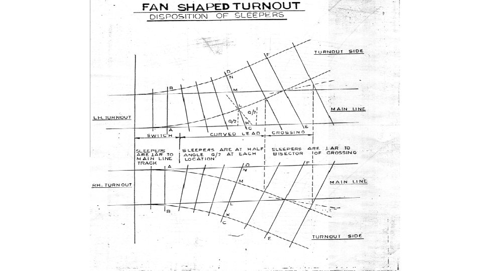
Turnouts on Concrete Sleepers § Orientation § Switch Portion§ Perpendicular to main line § Lead Portion • Laid with sleeper axis along direction of bisector of perpendiculars drawn to the mainline and to the turnout side. at an angle of /2 where, is the angle between the perpendicular to main line and the perpendicular to the tangent drawn on gauge face of outer rail of turnout at that point ( goes on increasing towards crossing) § Crossing Portion§ Sleepers axis perpendicular to bisector of crossing angle. (spacing along the bisector of crossing angle)
17
Interchangeability of Sleepers on LH/RH Turnouts 90 - /2 RE RE 90 - /2
Orientation of Sleeper in Fan Shaped Layout Area X Area Y Area Z Type of layout Switch area sleepers laid perpendicular to main line Lead area sleepers laid along the direction of bisector Crossing area sleepers laid perpendicular to centre line of crossing 1 in 12 1 to 20 21 to 65 66 to 83 1 in 8. 5 1 to 13 14 to 41 42 to 54
Features of Turnouts on Concrete Sleepers • Spacing of sleepers in switch portion § Uniform spacing except for the sleepers near ATS ( to accommodate S & T fittings)
Precautions during assembling • Compatibility of material. • Spreading of sleeper as per drawing (“RE” mark which indicates the right end of sleeper should be kept always on Right Hand Side irrespective of whether it is right or left hand turnout. ) • Cleaning of dowels • Checking of pre-curvature of tongue rail or stock rail. • Pre-bending of stock rail at TTS (In case of 1: 8. 5 turnouts TTS is 439 mm away from ATS, so at SRJ the bending should be by 14. 5 mm the gauge between stock rails at the location of ATS is equal to nominal gauge + 6 mm“ ). • Correct fixing of switches (absence of force at JOH gap cannot be made zero, keeping in view minimum setting up to 4 sleepers for 1 in 12 turnouts and up to 3 sleepers for 1 in 81/2 turnouts to be ensure.
Precautions during assembling • Correct fixing of switches (absence of force at JOH gap cannot be made zero, keeping in view minimum setting up to 4 sleepers for 1 in 12 turnouts and up to 3 sleepers for 1 in 81/2 turnouts to be ensure). • Difficult to correct setting for 4 or 3 sleepers as required, it could be because one or more of the following reasons Ø Pre-curvature of tongue rail not provided properly. ØWhile fixing stretcher bar, back to back distance between the webs of tongue rails have not been maintained as per design. ØStretcher bars should be of standard length. ØInadequate throw of switch. ØNon fixing of stretcher bar at half throw.
Precautions during assembling • Fixing of stretcher bar at half throw. • 2 holes of leading stretcher bar are required to be drilled in situ to fix other tongue rail in such a way that back to back distance of the web/web stiffener of tongue rails is maintained as per drawing. • There should be a clearance of 1. 5 mm to 3 mm between the bottom of Stock Rail and top of stretcher bar. • Stretcher bar should not be bent. • All stretcher bar bolts must be provided. • In track circuited territory, stretcher bar should be insulated. Back to back distances between webs of tongue rails in mm Turnout 1 in 12 1 in 8. 5 1 in 16 60 KG 52 KG 60 KG Leading S. Bar 1530. 5 1558 1559 1526 1 st Following S. Bar 1544 1545 1577. 5 1578 1543 2 ND Following S. Bar 1566 1596. 5 1546 3 rd Following S. Bar 1576 1579 ----- 1593
Precautions during assembling • Throw of switch to be maintained as 115 ± 3 mm. (ORS) • For TWS 160 ± 3 mm • Provision of proper stud bolts - Ensure that for the initial few sleepers only half headed stud bolts are used, so as not to present any obstruction between web of stock rail and tongue rail while butting against each other. • Use of slide chair with defective lugs - The horizontal piece of lug is connected to the slide chair with the help of welding. This welding may get cracked because of carelessness during handling. This should be checked and if required welding may be resorted to. • Use of proper distance block and special bearing plate: Maintenance of gauge and alignment in this part depends on use of proper distance block. So all such blocks should be checked as per drawing and the actual offset of tongue rail should also be checked to ensure proper fixing.
Precautions during assembling • Provision of proper stud bolts. • There are two types of stud bolts used in switch assembly for fixing the stock rail with the slide chairs. • One with the thinner head known as ‘half headed’ stud bolt and other with normal size of head called stud bolt. • Ensure that for the initial few sleepers only half headed stud bolts are used, so as not to present any obstruction between web of stock rail and tongue rail while butting against each other. • In case of breakage of such bolts, it should be replaced by half headed bolts only.
Precautions during assembling • Use of slide chair with defective lugs. • The stock rail is fastened to the lugs of slide chair with the help of stud bolts. • The horizontal piece of lug is connected to the slide chair with the help of welding. • This welding may get cracked due to carelessness handling. This should be checked and if required welding may be resorted to. • In new design rivet is also provided to hold the plates together, and has shown better performance.
Precautions during assembling • Use of proper switch stops and slide blocks – These are provided to transfer lateral force exerted by wheel on the tongue rails to stock rails. Switch Stops or slide blocks of proper design are required to be provided as per drawing. Switch stops are bolted to tongue rail whereas slide blocks are bolted to stock rail. • In 1 in 8 ½ turnouts switch stops are provided, whereas in 12, 1 in 16 and 1 in 20, slide blocks are provided. • Welding of SRJ - It is recommended practice to weld SRJ to the extent possible. If it is not possible to weld SRJ, it should be made as machined joint.
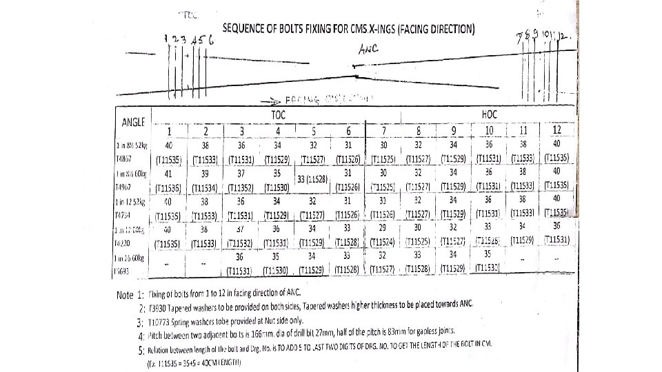
Precautions during assembling • Machined/gapless joint • Due to running of heavy axle loads, there is severe hammering action at the joints between CMS crossing and adjoining rails by the wheels of running trains. • Effect ØLoosening of bolts and nuts of fish plates of CMS crossing. Ø Damage to concrete sleepers. Ø Frequent wear and tear of rails, Ø Battering of joints • Solution – provision of Machined / gapless joint • Joints in turnouts are to be either made machined/gapless or welded as per drawing.
Precautions during assembling • Machined/gapless joint • CMS crossing and adjoining rails diameter of hole is kept 26. 5 mm. • Centre of 1 st hole from rail end is 83 mm. • Centre to centre distance between 1 st and 2 nd hole is 166 mm. • Centre to centre distance between 2 nd and 3 rd hole is 166 mm. • As per above arrangement joint are made gapless joint
Precautions during assembling • Machined/gapless joint • As per above arrangement maximum gap comes to 3. 5 mm at temperature lower than at time of installation. • This is literally not a gapless joint, it is rather joint with less gap. • Advantages of Gapless joint Ø Reduce hammering action at the joint. Ø Reduction in wear of rail. ØReduction in battering of rail. ØReduction in loosening of bolts. ØReduce damage to sleepers thereby increasing life of CMS and its components. ØChecking elongation of bolt hole provided greasing of fishplates carried out frequently and lateral and vertical misalignment during making of joint is ensured. ØEnhancement in safety of running of trains due to reduction of impact load at joint
Gapless Joint Fishplate Rail Hole in Rail Dia 26. 5 mm 83 mm Fishplate hole Dia 27 mm 56 mm 166 mm Fish Bolt dia 25 mm 3. 5
Precautions during assembling • Gauge tie plate - One gauge tie plate is used i. e. under ATS at sleeper number 3. for holding gauge at ATS in addition to take care of heavy thrust coming at ATS. This should be of insulated type. • Spherical washers - Used to obtain flush fit of the head or the nut of bolt with the web of Rail. • Required if axis (shank) of bolt is not at right angles to the axis of Rail (surface against which bolt will rest)
Spherical Washers
Effect of non provision of spherical washers
Position of spherical washers at heel and distance blocks • At heel of switch and distance blocks behind heel, spherical washers are to be provided on the left hand side irrespective of whether it is a left hand turnout or right hand turnout.
Spherical Washers Training of keymen about proper fixing of spherical washers is very important. If Keyman, is not properly trained, may fix washers on either wrong side or fix it wrongly. In such cases, only one side of head of bolt will come in contact with rail leading to eccentric forces. This will set a bending moment in the bolt. This bolt is likely to bend and break with in few days again.
Precautions during assembling • Special approach and exit sleepers • Points and Crossings are laid without Cant • Approach rails are Canted (1 in 20) • Running out Cant on Approaches • Improper fishing at SRJ and Heel of Crossing • Reverse canting of sleepers in 4 sleepers • On all three sides • 1 AS, 2 AS, 3 A, 4 A, 60 S (Before SRJ) • 1 E, 2 E, 3 E, and 4 E (Beyond Heel of Crossing) (on both Straight and Turnout side)
Running out Cant on Approaches
Running out Cant on Approaches
Precautions during assembling • Provision of proper liners Turnout with 60 kg rail Turnout with 52 kg rail Location Inside Outside Crossing 3706 3702 Check rail 3706 3708 Special bearing plate Sl no. 21 -27 (1 in 12) Sl no. 15 -17 (1 in 8. 5) 3706 3702 Rest of lead curve 3706 3707 3708
Precautions during assembling • Gauge at nose on crossing • Where crossing is not exactly at centre, slack or tight gauge on one of the track will lead to tight or slack gauge on the other track. Tight gauge may lead to the possibility of wheel flange hitting the nose of crossing; Too slack gauge at ANC is likely to cause more wear to check rails. Hence gauge to a better accuracy should be maintained on crossing. Permissible gauge in crossing portion. Crossing of turnout New laying and Maintenance PSC sleeper 1673 to 1677 ( N to +4 ) Other than PSC sleeper 1676 to 1680 ( N to +4 )
Precautions during assembling • Check rail clearance • Check rail provides lateral guidance to the wheel in the unguided gap between throat of crossing to ANC in the crossing area. • Opening of flared end is 68. 75 mm, this opening has been designed wide enough to trap any wheel without allowing any possibility for it to hit tip of check rail. Permissible check rail clearance in mm opposite nose of crossing. PSC sleeper 41 to 45 Other than PSC sleeper 44 to 48
Machined Check Rail Running Rail Gauge Face 227. 5 1500 875 227. 5 1500 68. 75 41 1415 4330 Check Rail Flare 1 in 70
Precautions during assembling • Provision of spring washers • Due to heavy vibrations transmitted during passage of traffic, various plate screws and bolts provided in turnout are likely to get loosened. • It is desirable to provide spring washers at all such locations to avoid loosening of screws and bolts. Vibrations are particularly heavy in crossing zone. • In the switch area spring washers should be used with stud bolts and plate screws.
Precautions during assembling • Rechecking of layout before replacement of turnout. • Overall length calculated should be checked with SRJ points at both lines. • If any false curve or other irregularities noticed it shall be removed. • Overall length provided shall be close to theoretical overall length if not it will lead to kinky alignment either on the main line side or on the cross over side.
Precautions during assembling • Display of date of laying of points & crossings • The month and year of laying a new or second hand points and crossings should be painted in white block letters on the webs of switches about 500 mm from the heel joint and the webs of crossings about 500 mm from the joint connected to the lead rails. • When second hand points and crossings are laid at another site, the dates previously marked should not be obliterated; an indication of the total life will then be available. • In the case of reconditioning of switches and crossings, the date of reconditioning should also be painted.
Do’s for laying Turnout • Check the availability of all components as per check list before laying in field. • Arrange switch and crossing of required rail section and crossing angle. • Decide on the method of laying depending upon land T-28 machine availability. • Lay approach and exit sleepers in proper sequence. • Before marking the SRJ locations please check the overall length required. • Pre curvature of tongue and stock rail to be checked before laying and corrected if required.
Do’s for laying Turnout • Ensure minimum throw of switch 115 ± 3 mm. • Ensure full compliment of fittings. • Ensure gapless joint at heel of switch and crossing. • Ensure proper fixing of spherical/taper washer. • In case of 52 kg. track on turnout, liners of proper design to be used. • Ensure proper setting of spring setting device. • Ensure sleepers spacing as per RDSO drawing for straight main line.
Works required before interlocking • Bring the rails to correct level and alignment. • Fully pack and ballast the points to be interlocked. • Provide creep indicators if required. • Mark places where the rods and wires have to cross the lines. • To avoid future adjustments of gear, see that the Permanent Way at points, is laid to correct gauge so that switches, fittings and locks may be correctly put together. • Clear formation and bring it to the correct level and section where rods and wires have to be run.
Works required before interlocking • Make the road at level crossings, if any to correct level and section to allow casing pipes for wires to be put in their final position. • Provide and fix special timbers as may be required. • Provide sufficient anchors of an approved type ahead of switches. • Fit gauge tie plates correctly to all switches.
Various Types of Turnouts with Curved Switches and CMS Crossings on Fan shaped PSC Sleepers BG (60/52 Kg) Rail Spec / Sleeper Layout T/O Drawing No Switch Drawing No Crossing Drawing no 52 KG /PSC 1 in 8. 5 RT 4865 (Alt 6 21. 7. 17) RT 4866 (Alt 6 21. 7. 17) RT 4867 (Alt 8 21. 7. 17) 60 KG / PSC 1 in 8. 5 RT 4865 (Alt 6 21. 7. 17) RT 4966 (Alt 5 21. 7. 17) RT 4967 (Alt 7 21. 7. 17) 52 KG /PSC 1 in 12 RT 4732 (Alt 4 27. 2. 17) RT 4733 (Alt 5 27. 2. 17) RT 4734 (Alt 5 27. 2. 17) 60 KG / PSC 1 in 12 RT 4218 (Alt 6 02. 11. 16) RT 4219 (Alt 6 02. 11. 16) RT 4220 (Alt 5 02. 11. 16) 60 KG /PSC 1 in 16 RT 5691 (Alt 3 05. 2. 18) RT 5692 (Alt 3 05. 2. 18) RT 5693 (Alt 1 05. 6. 03) 60 KG /PSC 1 in 20 RT 5858 RT 5859 RT 5860 52 KG /PSC 1 in 8. 5 S/S RT 5353 (Alt 2 21. 4. 98) RT 5354 (Alt 3 01. 5. 10) RT 4867 (Alt 8 21. 7. 17) 60 KG / PSC 1 in 8. 5 S/S RT 5353 (Alt 2 21. 4. 98) RT 5354 (Alt 3 01. 5. 10) RT 4967 (Alt 7 21. 7. 17)
Various Types of Turnouts with Curved Switches and CMS Crossings on Fan shaped PSC Sleepers BG (60/52 Kg) Rail Spec / Sleeper Layout T/O Drawing No Switch Drawing No Crossing Drawing no 52 KG /PSC 1 in 12 S/S RT 5553 RT 5554 RT 4734 (Alt 5 27. 2. 17) 60 KG / PSC 1 in 12 S/S RT 5553 RT 5554 RT 4220 (Alt 5 02. 11. 16) 60 KG / PSC TWS 1 in 8. 5 RT 6279 RT 6280 RT 4967 (Alt 7 21. 7. 17) 52 KG / PSC TWS 1 in 12 RT 5268 RT 5269 RT 4734 (Alt 5 27. 2. 17) 60 KG / PSC TWS 1 in 12 RT 6154 (Alt 3 12. 17) RT 6155 (Alt 5 08. 6. 18) RT 4220 (Alt 5 02. 11. 16) 60 KG / PSC TWS 1 in 16 RT 7075 RT 7076 RT 5693 (Alt 1 05. 6. 03)
30 40 11856 30 11 44 32 43 32 12356 T-4218 for 1 in 12, 60 kg
52 69 52 23 31 23 7620 T-4865 for 1 in 8. 5, 60/52 kg
Maintenance of Turnouts in Curve The turnouts are supposed to be laid on straight track as spacing are given according to ML as straight. But it is required to be laid T/O on curve in field due to existing track geometry 59
Following problems have been observed while laying fan shaped layout on curve • Track circuiting may fail because of rail touching to insert. • It may not be possible to insert liner at few sleepers. • Breakage of pendrol clip. • Incorrect gauge. . Inadequate toe load. • Breakage of GFN liners. • Inadequate holding of CMS Xing. • At few places rail foot may even cut the inserts. 60
Gap is too much causing poor toe load/breakage of GFN liner 61
Less Gap Excess Gap In correct gap for liners 62
No space for liner setting at Xing 63
Rail cutting into insert 64
MODIFICATION REQUIRED IN THE EXISTING LAYOUT • Change in spacing of sleepers to suit curved track for main line track • Pre-curving of stock and tongue rail to suit the curvature. 65
MODIFICATION REQUIRED • Based on the geometry two different solutions for Similar flexure as well as Contrary flexure are required. • The solutions has been made for all the curves from 0. 50 to 40 at a step of 0. 50. (limits of curvature may be applied in field as per IRPWM. ) • Simple tables have been made to facilitate the work by SSE (P way). Cumulative spacing has also been given which should be preferably followed. • For Similar flexure laying of 1: 8 ½ turnout is not permissible hence solution has not been made. 66
Re-spacing of sleeper So the sleeper are to be rotated by an angle equal to the angle subtended by the ML curve at the center. 67
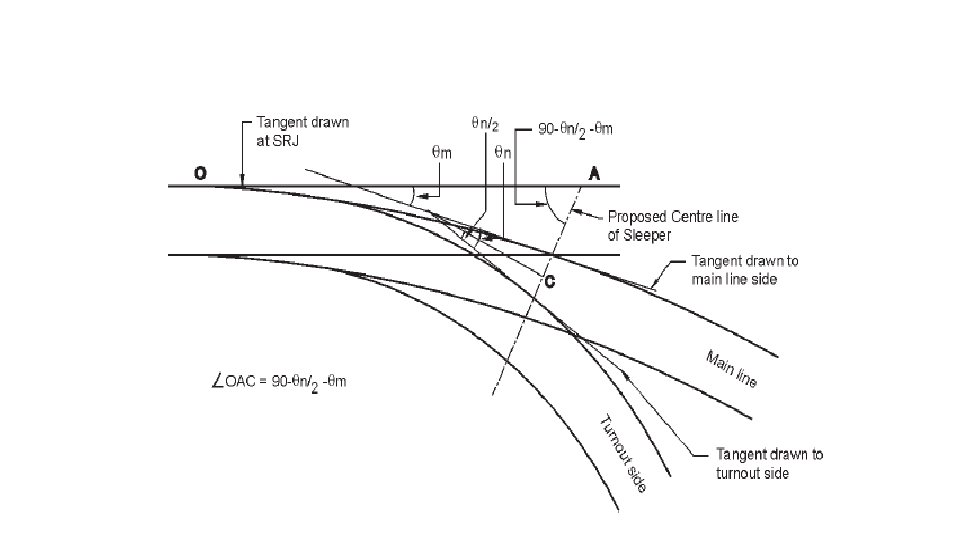
Orientation of sleepers when turnouts laid in curves • while laying the turnout on the curve, the tangent drawn to the main line is also changing direction along with the location. • The tangent drawn to the main line of turnout at the location of sleeper makes an angle of θm with the tangent drawn to the SRJ. • To maintain sleeper perpendicular to the bisector of the angle made by tangents drawn to main line and turnout side, the sleepers will also be required to be further rotated by an angle equal to the θm since it makes an angle of (90 -θn/2 -θm) with the tangent drawn to SRJ.
Orientation of sleepers when turnouts laid in curves • This additional rotation will reflect into change in the spacing of all the sleepers on the lead portion. • Such changes will depend on Ø The type of turnout Ø Degree of main line curve Ø The turnout is similar flexure or contrary flexure.
Orientation of sleepers when turnouts laid in curves • The sleeper spacing can be increased or decreased on both the rails of main line track as compared to the spacing given in the standard drawing of RDSO. • Since ERC can be fixed on CMS crossing at certain pre -decided locations it is better that the spacing is not changed on the rail of mainline on which crossing is likely to come i. e. the side on which train negotiates tongue rail while going towards main line. • Hence the spacing of sleeper 21 to 65 is changed on the side on which crossing is not coming.
Orientation of sleepers when turnouts laid in curves • The change in spacing is also required between sleeper No. 1 to 20 by the same principle but since holes in the stock rails are received drilled from the factory spacing on the switch area cannot be changed • But the total difference of spacing occrued between sleeper No. 1 to 20 is required to be adjusted between sleeper No. 20 -21 on 1 in 12 turnout and between sleeper no. 13 -14 in 1 in 8. 5 turnout. • In the crossing area sleepers are laid perpendicular to the bisector to the crossing legs. Same principle is applied while laying the turnout on the curve. Hence the sleepers are also required to be oriented along the direction perpendicular to the bisector of the crossing.
73
3 74
TABLE FOR CONTRARY FLEXURE, 1: 12 TURNOUT ON PSC Sle. No. Spacing on gauge face on tongue rail for ML side ( A side) Spacing on gauge face of stock rail for ML side ( B side) For All locations Spacing Cumul. 150 1 spacing 150 2 1797 552 5 552 2349 550 6 2349 550 2899 550 7 550 3449 550 3999 550 550 550 4549 550 5099 550 5649 4549 5099 4549 550 5099 550 5649 3999 550 550 5649 550 550 3449 3999 4549 5099 550 550 2899 3449 3999 4549 550 550 2349 2899 3449 3999 552 550 1797 2349 2899 3449 3999 4549 10 550 1797 2349 2899 1112 685 552 550 607 505 685 552 550 457 1112 1797 2349 2899 3449 8 552 150 607 1112 Cumul. 150 505 685 spacing 150 607 1797 Cumul. 457 505 685 spacing 4 degree 150 457 1112 1797 Cumul. 150 607 1112 3 degree 150 505 685 spacing 150 607 1112 Cumul. 457 505 685 spacing 2 degree 150 457 505 4 Cumul. 150 607 3 1 degree 150 457 11 Straight 5099 550 5649 75 5649
Sle. No. Spacing on A side Spacing on gauge face of stock rail for ML side ( B side) For All locations 550 12 550 6199 550 13 6199 6749 14 15 550 7849 550 16 550 17 550 8949 550 18 550 550 550 526 550 549 539. 36 11149 550 11674 549. 48 11699 550 12223 549. 48 12249 11117 11677 11106 547. 9 11666 548. 42 12226 10599 507. 44 548. 42 548. 95 12237 550 518. 08 548. 95 10049 10599 11128 11688 550 528. 72 9499 10049 10599 11138 550 550 8949 9499 10049 10599 550 550 8399 8949 9499 10049 10599 11125 22 550 550 7849 8399 8949 9499 10049 10599 21 550 550 7299 7849 8399 8949 9499 10049 20 550 550 6749 7299 7849 8399 8949 9499 19 550 550 6199 6749 7299 7849 8399 550 4 degree 550 6199 6749 7299 3 degree 550 6199 6749 7299 2 degree 550 550 1 degree 550 550 23 Straight 11654 547. 9 12214 76 12202
Sle. No. Spacing on A side Spacing on gauge face of stock rail for ML side ( B side) For All locations 549 24 550 12772 549 25 12799 13321 26 27 14419 28 14449 14968 549 29 14999 550 15517 549 30 15549 550 16066 549 31 16099 550 16615 549 32 16649 550 17164 549 33 17199 550 17713 549 34 17749 550 18262 549 18299 550 18811 18849 17698 18264 17681 547. 9 18247 548. 42 18813 17133 547. 9 548. 42 548. 95 18831 17150 17715 18282 16585 547. 9 548. 42 548. 95 549. 48 16601 17166 17732 16038 547. 9 548. 42 548. 95 549. 48 16053 16617 17183 15490 547. 9 548. 42 548. 95 549. 48 15504 16068 16633 14942 547. 9 548. 42 548. 95 549. 48 14956 15519 16084 14394 547. 9 548. 42 548. 95 549. 48 14408 14970 15534 13846 547. 9 548. 42 548. 95 549. 48 13859 14421 14985 13298 547. 9 548. 42 548. 95 549. 48 13311 13872 14435 12750 547. 9 548. 42 548. 95 549. 48 12762 13324 13886 4 degree 547. 9 548. 42 548. 95 549. 48 550 12775 13336 13899 3 degree 548. 42 548. 95 549. 48 550 549 12787 13349 13870 2 degree 548. 95 549. 48 550 549 1 degree 549. 48 550 549 35 Straight 18229 547. 9 18795 77 18777
Sle. No. Spacing on A side Spacing on gauge face of stock rail for ML side ( B side) For All locations 549 36 550 19360 549 37 19399 19909 38 39 21007 40 21049 21556 549 41 21599 550 22105 549 42 22149 550 22654 549 43 22699 550 23203 549 44 23249 550 23752 549 45 23799 550 24301 549 46 24349 550 24850 549 24899 550 25399 25449 24279 24851 24256 547. 9 24828 548. 42 25400 23708 547. 9 548. 42 548. 95 25425 23731 24303 24875 23160 547. 9 548. 42 548. 95 549. 48 23182 23754 24326 22612 547. 9 548. 42 548. 95 549. 48 22634 23205 23776 22064 547. 9 548. 42 548. 95 549. 48 22085 22656 23227 21517 547. 9 548. 42 548. 95 549. 48 21537 22107 22677 20969 547. 9 548. 42 548. 95 549. 48 20989 21558 22128 20421 547. 9 548. 42 548. 95 549. 48 20440 21009 21578 19873 547. 9 548. 42 548. 95 549. 48 19892 20460 21029 19325 547. 9 548. 42 548. 95 549. 48 19343 19911 20479 4 degree 547. 9 548. 42 548. 95 549. 48 550 19362 19930 20499 3 degree 548. 42 548. 95 549. 48 550 549 19380 19949 20458 2 degree 548. 95 549. 48 550 549 1 degree 549. 48 550 549 47 Straight 24804 547. 9 25376 78 25352
Sle. No. Spacing on A side Spacing on gauge face of stock rail for ML side ( B side) For All locations 549 48 550 25948 549 49 25999 26497 50 51 27595 52 27649 28144 549 53 28199 550 28693 549 54 28749 550 29242 549 55 29299 550 29791 549 56 29849 550 30340 549 57 30399 550 30889 549 58 30949 550 31438 549 31499 550 31987 32049 30860 31439 30831 547. 9 31409 548. 42 31988 30283 547. 9 548. 42 548. 95 32018 30312 30890 31469 29735 547. 9 548. 42 548. 95 549. 48 29763 30341 30919 29187 547. 9 548. 42 548. 95 549. 48 29215 29792 30370 28639 547. 9 548. 42 548. 95 549. 48 28667 29243 29821 28091 547. 9 548. 42 548. 95 549. 48 28118 28694 29271 27543 547. 9 548. 42 548. 95 549. 48 27570 28145 28722 26996 547. 9 548. 42 548. 95 549. 48 27021 27596 28172 26448 547. 9 548. 42 548. 95 549. 48 26473 27047 27623 25900 547. 9 548. 42 548. 95 549. 48 25924 26498 27073 4 degree 547. 9 548. 42 548. 95 549. 48 550 25949 26524 27099 3 degree 548. 42 548. 95 549. 48 550 549 25974 26549 27046 2 degree 548. 95 549. 48 550 549 1 degree 549. 48 550 549 59 Straight 31379 547. 9 31957 79 31927
Sle. No. Spacing on A side Spacing on gauge face of stock rail for ML side ( B side) For All locations 549 60 550 32536 548 61 32599 33084 62 63 34182 64 34249 34731 549 65 34799 550 35280 550 66 35349 550 35830 550 67 35899 550 36380 550 68 36449 550 36930 550 69 36999 550 37480 550 70 37549 550 38030 550 38099 550 38580 38649 37443 38029 37408 548. 39 37992 548. 92 38578 36859 548. 39 548. 92 549. 45 38614 36894 37479 38064 36311 548. 39 548. 92 549. 45 549. 73 36345 36930 37514 35762 548. 39 548. 92 549. 45 549. 73 35796 36380 36964 35214 548. 39 548. 92 549. 45 549. 73 35248 35831 36415 34666 547. 9 548. 92 549. 45 549. 73 34699 35282 35865 34118 547. 9 548. 42 549. 45 549. 73 34151 34733 35315 33570 547. 9 548. 42 548. 95 549. 73 33602 34184 34766 33022 547. 9 548. 42 548. 95 549. 48 33054 33635 34216 32475 547. 9 548. 42 548. 95 549. 48 32505 33086 33667 4 degree 547. 9 548. 42 548. 95 549. 48 550 32537 33117 33699 3 degree 548. 42 548. 95 549. 48 550 549 32568 33149 33633 2 degree 548. 95 549. 48 550 549 1 degree 549. 48 550 549 71 Straight 37956 548. 39 38541 80 38504
Sle. No. Spacing on A side Spacing on gauge face of stock rail for ML side ( B side) For All locations 550 72 550 39130 550 73 39199 39680 74 75 40780 76 40849 41330 550 77 41399 550 41880 550 78 41949 550 42430 550 79 42499 550 42980 550 80 43049 550 43530 550 81 43599 550 44080 550 82 44149 550 44630 550 44699 550 45180 45249 44030 44622 43988 548. 39 44579 548. 92 45172 43440 548. 39 548. 92 549. 45 45210 43481 44073 44661 42892 548. 39 548. 92 549. 45 549. 73 42932 43523 44111 42343 548. 39 548. 92 549. 45 549. 73 42384 42974 43561 41795 548. 39 548. 92 549. 45 549. 73 41835 42424 43011 41246 548. 39 548. 92 549. 45 549. 73 41286 41875 42462 40698 548. 39 548. 92 549. 45 549. 73 40737 41325 41912 40150 548. 39 548. 92 549. 45 549. 73 40188 40776 41362 39601 548. 39 548. 92 549. 45 549. 73 39639 40227 40813 39053 548. 39 548. 92 549. 45 549. 73 39090 39677 40263 4 degree 548. 39 548. 92 549. 45 549. 73 550 39128 39713 40299 3 degree 548. 92 549. 45 549. 73 550 39163 39749 40230 2 degree 549. 45 549. 73 550 1 degree 549. 73 550 83 Straight 44537 548. 39 45128 81 45085
TABLE FOR SIMILAR FLEXURE, 1: 12 TURNOUT ON PSC Spacing on gauge face on tongue rail for ML side(A side) Sle. No. For all locations Spac. cumul. 150 1 Straight Spac. 150 2 4 552 5 552 2349 550 6 2349 550 2899 550 7 550 3449 550 3999 550 550 550 4549 550 5099 550 5649 4549 5099 4549 550 5099 550 5649 3999 550 550 5649 550 550 3449 3999 4549 5099 550 550 2899 3449 3999 4549 550 550 2349 2899 3449 3999 552 550 1797 2349 2899 3449 3999 4549 10 550 1797 2349 2899 1112 685 552 550 607 505 685 552 550 457 1112 1797 cumul. 150 607 1112 2349 2899 3449 8 552 Spac. 150 505 685 4 degree 150 607 1797 cumul. 457 505 685 Spac. 150 457 1112 1797 cumul. 3 degree 150 607 1112 1797 Spac. 150 505 685 2 degree 150 607 1112 cumul. 457 505 685 Spac. 150 457 505 1 degree 150 607 3 cumul. 150 457 11 spacing on gauge face of stock rail for ML side ( B side) 5099 550 5649 82
TABLE FOR SIMILAR FLEXURE, 1: 12 TURNOUT ON PSC Spacing on gauge face on tongue rail for ML side(A side) Sle. No. For all locations Spac. cumul. 150 1 Straight Spac. 150 2 4 552 5 552 2349 550 6 2349 550 2899 550 7 550 3449 550 3999 550 550 550 4549 550 5099 550 5649 4549 5099 4549 550 5099 550 5649 3999 550 550 5649 550 550 3449 3999 4549 5099 550 550 2899 3449 3999 4549 550 550 2349 2899 3449 3999 552 550 1797 2349 2899 3449 3999 4549 10 550 1797 2349 2899 1112 685 552 550 607 505 685 552 550 457 1112 1797 cumul. 150 607 1112 2349 2899 3449 8 552 Spac. 150 505 685 4 degree 150 607 1797 cumul. 457 505 685 Spac. 150 457 1112 1797 cumul. 3 degree 150 607 1112 1797 Spac. 150 505 685 2 degree 150 607 1112 cumul. 457 505 685 Spac. 150 457 505 1 degree 150 607 3 cumul. 150 457 11 spacing on gauge face of stock rail for ML side ( B side) 5099 550 5649 83
TABLE FOR SIMILAR FLEXURE, 1: 12 TURNOUT ON PSC Spacing on gauge face on tongue rail for ML side(A side) Sle. No. For all locations 550 12 Straight 550 6199 550 13 6199 6749 14 15 7849 16 7849 8399 550 17 8399 550 8949 550 18 8949 550 9499 550 19 9499 550 10049 550 20 10049 550 10599 526 21 10599 550 11125 548 11149 550 11673 11699 10599 11170 10599 592. 6 11181 551. 6 11721 10049 550 581. 9 551. 1 11712 10049 10599 11162 9499 550 571. 3 550. 5 9499 10049 10599 8949 550 550 562. 6 8949 9499 10049 8399 550 550 8399 8949 9499 7849 550 550 7849 8399 8949 7299 550 550 7299 7849 8399 6749 550 550 6749 7299 7849 6199 550 550 6199 6749 7299 4 degree 550 550 550 6199 6749 7299 3 degree 550 550 550 6199 6749 7299 2 degree 550 550 1 degree 550 550 22 spacing on gauge face of stock rail for ML side ( B side) 11192 552. 1 11732 11744 84
TABLE FOR SIMILAR FLEXURE, 1: 12 TURNOUT ON PSC Sle. No. Spacing on gauge face on tongue rail for ML side(A side) For all locations 549 23 spacing on gauge face of stock rail for ML side ( B side) Straight 550 12222 549 24 12249 12771 25 549 550 549 27 550 14418 548 28 550 549 550 549 550. 5 17749 550. 5 16713 552. 1 17248 551. 6 17783 551. 1 552. 1 551. 6 551. 1 16160 16697 17232 17768 552. 1 551. 6 551. 1 15608 16145 16681 17217 552. 1 551. 6 551. 1 15056 15594 16130 16667 17199 17711 549 550. 5 552. 1 551. 6 551. 1 14504 15042 15579 16116 16649 17162 33 550. 5 552. 1 551. 6 551. 1 13952 14490 15028 15566 16099 16613 32 550. 5 552. 1 551. 6 551. 1 13400 13939 14477 15015 15549 16064 31 550. 5 552. 1 551. 6 551. 1 12848 13387 13926 14465 14999 15515 30 550. 5 552. 1 551. 6 551. 1 12296 12836 13374 13914 14449 14966 29 550. 5 552. 1 551. 6 551. 1 4 degree 12284 12823 13364 13899 551. 6 551. 1 550. 5 3 degree 12272 12813 13349 13869 551. 1 550. 5 550 2 degree 12263 12799 13320 26 550. 5 550 549 1 degree 17265 552. 1 17800 551. 6 17817 552. 1 85
TABLE FOR SIMILAR FLEXURE, 1: 12 TURNOUT ON PSC Spacing on gauge face on tongue rail for ML side(A side) Sle. No. For all locations 34 Straight 18260 549 35 18809 36 18849 19358 37 19906 548 38 19949 20454 39 20499 21003 549 40 21049 550 21552 549 41 21599 550 22101 549 42 22149 550 22650 549 43 22699 550 23199 549 23249 550 23748 23799 22764 23293 22786 552. 1 23316 551. 6 23844 22234 552. 1 551. 6 551. 1 23824 22212 22742 23273 21682 552. 1 551. 6 551. 1 550. 5 21661 22191 22723 21129 552. 1 551. 6 551. 1 550. 5 21109 21640 22172 20577 552. 1 551. 6 551. 1 550. 5 20558 21089 21622 20025 552. 1 551. 6 551. 1 550. 5 20006 20538 21071 19473 552. 1 551. 6 551. 1 550. 5 19455 19987 20521 18921 552. 1 551. 6 551. 1 550. 5 18903 19436 19970 18369 552. 1 551. 6 551. 1 550. 5 550 18885 19420 4 degree 18351 551. 6 551. 1 550. 5 550 549 18869 19399 3 degree 18334 551. 1 550. 5 550 2 degree 18318 550. 5 550 548 1 degree 18299 550 549 44 spacing on gauge face of stock rail for ML side ( B side) 23338 552. 1 23867 23890 86
TABLE FOR SIMILAR FLEXURE, 1: 12 TURNOUT ON PSC Spacing on gauge face on tongue rail for ML side(A side) Sle. No. For all locations 549 45 Straight 550 24297 549 46 24349 24846 47 48 25944 49 25999 26493 549 50 26549 550 27042 549 51 27099 550 27591 549 52 27649 550 28140 549 53 28199 550 28689 54 28749 550 29238 549 29299 550 29787 29849 28831 29355 28859 552. 1 29383 551. 6 29906 28307 552. 1 551. 6 551. 1 29880 28280 28804 29329 27755 552. 1 551. 6 551. 1 550. 5 27728 28253 28778 27203 552. 1 551. 6 551. 1 550. 5 27177 27702 28228 26650 552. 1 551. 6 551. 1 550. 5 26625 27151 27677 26098 552. 1 551. 6 551. 1 550. 5 26073 26600 27127 25546 552. 1 551. 6 551. 1 550. 5 25522 26049 26576 24994 552. 1 551. 6 551. 1 550. 5 24970 25498 26026 24442 552. 1 551. 6 551. 1 550. 5 24419 24947 25475 4 degree 552. 1 551. 6 551. 1 550. 5 550 24396 24925 25449 3 degree 551. 6 551. 1 550. 5 550 549 24374 24899 25395 2 degree 551. 1 550. 5 550 549 1 degree 550. 5 550 549 55 spacing on gauge face of stock rail for ML side ( B side) 29411 552. 1 29935 29963 87
TABLE FOR SIMILAR FLEXURE, 1: 12 TURNOUT ON PSC Spacing on gauge face on tongue rail for ML side(A side) Sle. No. For all locations 549 56 Straight 550 30336 549 57 30399 30885 58 59 31983 60 32049 32532 548 61 32599 550 33080 549 62 33149 550 33629 549 63 33699 550 34178 549 64 34249 550 34727 549 65 34799 550 35276 550 35349 550 35826 35899 34899 35417 34932 552. 1 35450 551. 6 35968 34380 552. 1 551. 6 551. 1 35935 34347 34866 35385 33828 552. 1 551. 6 551. 1 550. 5 33796 34314 34834 33276 552. 1 551. 6 551. 1 550. 5 33244 33763 34284 32724 552. 1 551. 6 551. 1 550. 5 32692 33212 33733 32171 552. 1 551. 6 551. 1 550. 5 32141 32661 33183 31619 552. 1 551. 6 551. 1 550. 5 31589 32110 32632 31067 552. 1 551. 6 551. 1 550. 5 31038 31559 32082 30515 552. 1 551. 6 551. 1 550. 5 30486 31008 31531 4 degree 552. 1 551. 6 551. 1 550. 5 550 30457 30981 31499 3 degree 551. 6 551. 1 550. 5 550 549 30430 30949 31434 2 degree 551. 1 550. 5 550 549 1 degree 550. 5 550 549 66 spacing on gauge face of stock rail for ML side ( B side) 35484 552. 1 36002 36036 88
TABLE FOR SIMILAR FLEXURE, 1: 12 TURNOUT ON PSC Spacing on gauge face on tongue rail for ML side(A side) Sle. No. For all locations 550 67 Straight 550 36376 550 68 36449 36926 69 70 38026 71 38099 38576 550 72 38649 550 39126 550 73 39199 550 39676 550 74 39749 550 40226 550 75 40299 550 40776 550 76 40849 550 41326 550 41399 550 41876 41949 40966 41478 41005 552. 1 41518 551. 6 42029 40453 552. 1 551. 6 551. 1 41991 40414 40927 41441 39901 552. 1 551. 6 551. 1 550. 5 39863 40376 40890 39349 552. 1 551. 6 551. 1 550. 5 39311 39825 40340 38797 552. 1 551. 6 551. 1 550. 5 38760 39274 39789 38245 552. 1 551. 6 551. 1 550. 5 38208 38723 39238 37693 552. 1 551. 6 551. 1 550. 5 37657 38172 38688 37140 552. 1 551. 6 551. 1 550. 5 37105 37621 38137 36588 552. 1 551. 6 551. 1 550. 5 36553 37070 37587 4 degree 552. 1 551. 6 551. 1 550. 5 550 36519 37036 37549 3 degree 551. 6 551. 1 550. 5 550 36486 36999 37476 2 degree 551. 1 550. 5 550 1 degree 550. 5 550 77 spacing on gauge face of stock rail for ML side ( B side) 41557 552. 1 42069 42109 89
TABLE FOR SIMILAR FLEXURE, 1: 12 TURNOUT ON PSC Spacing on gauge face on tongue rail for ML side(A side) Sle. No. For all locations 550 78 Straight 550 42426 550 79 42499 42976 80 81 44076 82 44149 44626 550 44699 550 45176 45249 44276 44784 44318 552. 1 44827 551. 6 45336 43766 552. 1 551. 6 551. 1 45294 43724 44233 44744 43214 552. 1 551. 6 551. 1 550. 5 43172 43682 44193 42661 552. 1 551. 6 551. 1 550. 5 42621 43131 43643 4 degree 552. 1 551. 6 551. 1 550. 5 550 42580 43092 43599 3 degree 551. 6 551. 1 550. 5 550 42542 43049 43526 2 degree 551. 1 550. 5 550 1 degree 550. 5 550 83 spacing on gauge face of stock rail for ML side ( B side) 44870 552. 1 45379 45422 90
1 in 8. 5 turnout contrary flexure turnout Slee per No. Spacing on gauge faceon tongue rail for ML side (A side) Spacing cumul. 300 1 Straight Spacing 300 2 2173 660 5 660 2773 600 6 2773 600 3373 600 7 600 3973 600 4573 600 9 600 600 5173 600 5773 600 6373 5173 5773 5173 600 5773 600 6373 4573 600 600 6373 600 600 3973 4573 5173 5773 600 600 3373 3973 4573 5173 600 600 2773 3373 3973 4573 660 600 2173 2773 3373 3973 4573 5173 10 600 2173 2773 3373 1513 600 660 600 900 613 600 660 600 1513 2173 2773 3373 3973 8 660 300 900 1513 cumul. 300 613 600 Spacing 300 900 2173 cumul. 600 613 600 Spacing 4 degree 300 600 1513 2173 cumul. 300 900 1513 3 degree 300 613 600 Spacing 300 900 1513 cumul. 600 613 600 Spacing 2 degree 300 613 4 cumul. 300 900 3 1 degree 300 600 11 Spacing on gauge face on stock rail for ML side (B side) 5773 600 6373 91
Sl. N o. Spacing on A side Spacing cumul. 600 12 Straight Spacing 6973 13 8734 597 16 600 9331 598 17 9373 600 9929 598 18 600 597 10573 600 11124 598 20 599. 43 600 598 599. 43 11773 600 12320 598 599. 43 12373 600 12918 599. 43 12973 11739 12349 11728 597. 71 12338 598. 28 12948 11130 597. 71 598. 28 598. 86 12961 597. 72 598. 28 598. 86 10533 11141 11751 12361 597. 71 598. 29 598. 86 9935 10543 11152 11762 597. 71 598. 28 598. 86 9337 9945 10553 11162 597. 72 598. 28 598. 86 8740 9346 9954 10563 11173 11722 21 599. 43 8748 9355 9964 8142 597. 72 598. 29 598. 86 7573 568. 88 598. 29 598. 86 599. 43 600 8150 8756 9364 9973 10527 19 599. 43 6973 7573 8157 cumul. 600 576. 66 598. 86 Spacing 6973 7573 8765 cumul. 600 584. 44 599. 43 Spacing 4 degree 600 8165 8773 cumul. 6973 7573 8173 3 degree 600 592. 22 600 Spacing 6973 7573 8137 cumul. 600 597 Spacing 2 degree 600 564 15 cumul. 6973 7573 14 1 degree 600 22 Spacing on gauge face on stock rail for ML side (B side) 12326 597. 71 12936 12924 92
Sl. N o. Spacing on A side Spacing cumul. 597 23 Straight Spacing 13515 24 15309 597 27 600 15906 598 28 15973 600 16504 598 29 600 598 17173 600 17700 597 31 599. 43 600 598 599. 43 18373 600 18895 598 599. 43 18973 600 19493 599. 43 19573 18321 18937 18303 597. 71 18919 598. 28 19536 17705 597. 72 598. 28 598. 86 19554 597. 71 598. 29 598. 86 17108 17722 18338 18955 597. 71 598. 28 598. 86 16510 17124 17739 18356 597. 71 598. 28 598. 86 15912 16526 17140 17756 597. 72 598. 28 598. 86 15314 15927 16541 17157 17773 18297 32 599. 43 15329 15943 16557 14717 597. 71 598. 29 598. 86 14119 597. 71 598. 28 598. 86 599. 43 597. 71 14731 15344 15958 16573 17102 30 599. 43 13521 14133 14745 cumul. 597. 72 598. 28 598. 86 Spacing 13534 14146 15358 cumul. 598. 28 598. 86 599. 43 Spacing 4 degree 598. 29 598. 86 14759 15373 cumul. 13547 14160 14773 3 degree 598. 86 599. 43 600 Spacing 13560 14173 14711 cumul. 599. 43 600 598 Spacing 2 degree 599. 43 600 598 26 cumul. 13573 14113 25 1 degree 600 598 33 Spacing on gauge face on stock rail for ML side (B side) 18901 597. 71 19517 19498 93
Sl. N o. Spacing on A side Spacing cumul. 598 34 Straight Spacing 20091 35 21884 598 38 600 22482 597 39 22573 600 23079 598 40 600 598 23773 600 24275 598 42 599. 43 600 550 599. 43 24973 550. 5 25423 550 549. 97 25524 550. 5 25973 549. 97 26074 24902 25475 24878 548. 39 25452 548. 92 26025 24280 597. 71 549. 97 549. 45 26049 597. 71 598. 28 549. 97 23682 24303 24925 25499 597. 71 598. 28 598. 86 23085 23705 24327 24949 597. 72 598. 28 598. 86 22487 23107 23728 24350 597. 71 598. 29 598. 86 21889 22509 23129 23750 24373 24873 43 599. 43 21910 22530 23151 21292 597. 71 598. 28 598. 86 20694 597. 71 598. 28 598. 86 599. 43 597. 72 21312 21931 22552 23173 23677 41 599. 43 20096 20714 21332 cumul. 597. 71 598. 28 598. 86 Spacing 20115 20733 21952 cumul. 598. 29 598. 86 599. 43 Spacing 4 degree 598. 28 598. 86 21353 21973 cumul. 20135 20753 21373 3 degree 598. 86 599. 43 600 Spacing 20154 20773 21286 cumul. 599. 43 600 598 Spacing 2 degree 599. 43 600 598 37 cumul. 20173 20688 36 1 degree 600 597 44 Spacing on gauge face on stock rail for ML side (B side) 25426 548. 39 26001 25975 94
Spacing on gauge face on stock rail for ML side (B side) Sl. N o. Spacing on A side Straight Spacing cumul. 550 45 26523 46 48 28173 550 49 28276 550. 5 28723 550 50 28827 550. 5 29273 550 51 550. 5 550 30478 550. 5 30923 550 549. 97 31029 550. 5 31473 549. 97 31579 31549 548. 39 30392 30970 30362 548. 39 30941 548. 92 31519 29813 548. 39 548. 92 549. 45 29265 29843 30420 30999 548. 39 548. 92 549. 45 28717 29294 29871 30449 548. 39 548. 92 549. 45 28168 28745 29322 29899 549. 97 28196 548. 92 549. 45 27620 548. 39 548. 92 549. 45 549. 97 27647 28772 29349 29928 30373 53 549. 97 27071 548. 39 548. 92 549. 45 28799 29377 29823 52 549. 97 26523 27098 28223 cumul. 548. 39 548. 92 549. 45 Spacing 548. 39 548. 92 27673 28249 cumul. 26549 27124 27699 4 degree 548. 92 549. 45 549. 97 Spacing 26574 27149 27726 cumul. 549. 45 549. 97 550. 5 Spacing 3 degree 549. 45 549. 97 550. 5 550 cumul. 26599 27175 27623 2 degree 549. 97 550. 5 550 Spacing 26625 27073 47 cumul. 550. 5 550 54 Spacing 1 degree 30910 548. 39 31490 95 31459
Precurvature of tongue and stock rail • It is a known fact that the curved switch manufactured for LH turnout can not be used for RH turnout because of difference in the pattern of machining of both the tongue rails. • In every curved switch, gauge face of pair of tongue rail and stock rail leading to turnout side is made curved with some curvature. • Curved tongue rail is machined straight up to JOH, as this is supposed to bear against straight stock rail. • Curved stock railand tongue rail are given certain predefined pre-curvature at the time of manufacturing.
Precurvature of tongue and stock rail • While laying fan shaped turnout on straight track, stock rail and tongue rail for turnout side is required to be checked for pre-curvature (by checking mid and quarter ordinate). • Versines at mid and quarter ordinates readings to be as per relevant drawings • Improper curvature of stock and tongue rail lead to Ø Improper housing of switch. Ø Variation in gauge and versine readings. . Ø Improper seating of tongue rail.
Precurvature of tongue and stock rail in curved track • While laying fan shaped turnout on straight track, stock rail and tongue rail for turnout side is required to be checked for pre-curvature (by checking mid and quarter ordinate). • Versines at mid and quarter ordinates readings to be as per relevant drawings which are true only for staright track. • Laying of fan shaped turnouts on curved track both the stock and tongue rails become curved and the precurvature requirements change according to the degree of curve and whether it is similar flexure or contrary flexure. • To ensure proper bearing of both the tongue rails proper pre-curvature is required.
Precurvature of tongue and stock rail in curved track • Pre-curvature requirements change according to the degree of main line curve and flexure of turnout (similar or contrary). • Stock as well as tongue rail are to be given required pre-curving for good setting of point. • A table for checking and providing pre-curving for Similar flexure as well as Contrary flexure turnout on curves of various degrees have been prepared. • The different method to be followed for checking of pre-curving for Similar as well as Contrary flexure turnout has also been given by schematic diagram. • It may not be possible to measure positive versine of one of the tongue rail of similar flexure (i. e. tongue rail for mainline side); hence the measurements of mid and quarter point should be done as per diagram
Table for pre-curving versine of stock and tongue rails when lain in curves in similar and contrary flexure 100
101
stock 102
Table 1 - For 1 in 12 Turnout with similar flexure 103
Table 2 - For Contrary flexure 1 in 12 104
Table 3 - For Contrary flexure 1 in 8. 5 105
Turn in curve
Turn in curve • Turnouts are always provided to connect 2 tracks, hence on divergent side after heel of crossing (or last long sleeper in case of PSC sleepers) track is laid to connect it to adjoining track. • This part of track may be straight or curving in any direction. • If it is curved in same direction, it is called connecting curve. • If this curve is in the direction opposite to the direction of lead curve, it is called turn in curve. (i. e. ) track portion between the heel of crossing to the fouling mark
Laying & Maintenance of Spring Setting Device
Spring Setting Device • It is a reversible mechanical spring device connected to the foot of two tongue rails at or near JOH • The device actuates after the movement of TRs initiated by the point motor reaches about half way • At this stage, one connecting rod of the SSD pulls the open TR away from SR and simultaneously the other connecting rod pushes the closed TR firmly against the SR
Spring Setting Device
Spring Setting Device • This prevents the rattling of TRs between TOE and HEEL under moving wheels and ensures adequate clearance between TR and SR. • Hence, enhanced life of switches and better riding comfort can be achieved. • RDSO Drg No. RT-6216 (60 kg)
Speed Potential on Turnouts
Permissible Speeds on Points & Crossings • Criteria For Permissible Speed On Main Line – Standard of Interlocking • Speeds on Main Line – Standard I Interlocking 50 kmph – Standard II Interlocking 75 kmph – Standard III Interlocking Unrestricted – Irrespective of interlocking, speed shall be restricted to 50 kmph in case of a point taking off in the block section
Permissible Speeds on Points & Crossings • Criteria For Permissible Speed On Main Line – Curvature of Main Line • Speeds on Main Line – No restriction in case of straight Main Line – Main line & Turnout having curvature in opposite direction • CANT given to mainline acts as negative CANT for turnout. • This restricts permissible speed on main line. – Main line & Turnout having curvature in same direction • CANT given to Main line is also given to Loop Lines. This puts restriction on permissible speed on Main Line.
Speed Potential on Turnouts • Factors which restricts speed potential on Turnout: – Abrupt change in direction at Toe of Switch quantified by Switch Entry Angle – Absence of Transition – Deficiency of Super elevation in lead – Discontinuity at Crossing – Un-transitioned entry from curved lead to straight crossing – Straight or un-flexed crossing. • However out of above only SEA has significant bearing on speed potential of T/O at low speeds.
Speeds on Points and Crossings Effect of SEA • Following feature of TO affect running over it ABRUPT CHANGE IN DIRECTION –resulting in lateral jerk on bogie and corresponding heavy lateral force on tongue rail. • The magnitude of the force primarily depends on Switch Entry Angle. • The SEA has therefore direct bearing on speed potential of Turnouts. • In fact this is the most important factor affecting the speed potential.
The D-72 Report of ORE (now, ERRI) has Recommended following SEAs for different speeds ORE ERRI SPEED (kmph) 40 60 100 SEA (d-m-s) 0 -40 -30 0 -25 -00 0 -15 -00 160 0 -08 -00 — Office Of Reseasrch and Experimentation — Europian Rail Research Institute (A body of UIC)
Absence of Transition • Absence of transition on entry from straight switch to curved lead or straight approach to curved switch causes lurch (lateral force) and primarily affects comfort. • The effect of absence of transition has been studied by ORE and the results indicate that at slow speeds this effect is not pronounced.
Deficiency of Super-elevation • Absence of super-elevation over Turnout causes UNBALANCED LATERAL ACCELERATION and affects SAFETY and COMFORT. • In European Railways, Switch Entry Angles are small and the permissible cant deficiency on the TO curves becomes main criteria for evaluating the permissible speed. • On IR this is a minor consideration as compared to SEA. • WHY?
Discontinuity at Crossing • Due to the gap, vertical impact forces are exerted on the nose of crossing. • Studies conducted by ORE have indicated that for speeds upto 200 kmph on the straight and 160 on turnout, it is not necessary to avoid this gap. • However, it can be avoided, with the objective of improving safety, with the comfort and maintainability. • SOLUTION : Movable nose crossing for speed beyond 160 Kmph.
Un-transitioned entry from curved lead to straight crossing Straight or un-flexed crossing • SOLUTION : Use of Curved Crossings
Theoretical Evaluation of Speed Potential on Turnout • The permissible speed over the turnout is the minimum of the following three speeds a) Permissible speed due to non transitioning of the lead curve b) Permissible speed due to non-canting of lead curve c) Permissible speed to obtain desirable values of lateral forces and acceleration at entry
Permissible speeds for various criteria Speed due to non-transitioning (KMPH) Speed due to non-provision of super elevation (KMPH) 43. 6 35. 8 0 47’ 27” 45. 0 36. 0 1 8’ 0” 68. 0 50. 0 0 27’ 35” 69. 4 51. 0 1 in 16 0 24’ 27” 95. 4 68. 8 1 in 16 (Symmetrical split) 0 12’ 13” 138. 0 97. 0 1 in 20 0 24’ 27” 122. 0 86. 4 Turnout 1 in 8. 5 (Straight Switch) 1 in 8. 5 (Curved Switch) 1 in 12 (Straight Switch) 1 in 12 (Curved Switch) SEA 1 34’ 37”
Flange forces depend to a greater extent on the angle of attack than on speed Angle of Attack Maximum Value of lateral forces (Tonnes) Speed 30 KMPH Speed 45 KMPH Speed 60 KMPH 0 12’ 0” 2. 4 3. 0 4. 0 0 24’ 0” 4. 9 5. 10 6. 50 0 34. 4’ 0” 7. 0 7. 50 10. 0 1 41. 5’ 0” 10. 0 11. 50 14. 9
Instrumented trials have revealed the following permissible speeds based on lateral forces exerted by vehicles while negotiating the switches - Type of Turnout 1 in 8. 5 (straight) 1 in 8. 5 (curved) 1 in 12 (straight) 1 in 12 (curved) 1 in 16 and 1 in 20 1 in 16 (high speed) SEA 1 34’ 27” 0 47’ 27” 1 08‘ 00” 0 27’ 35” 0 24’ 27” 0 17’ 11” Speed Potential 10 kmph 25 kmph 15 kmph 42 kmph 55 kmph 80 kmph
Based on the Field Trial results and Limiting values of Parameters, the Speed Potential for different Turnouts has been prescribed by RDSO
Speed Potential on BG Description 1 in 8 ½ - Straight Switch 1 in 8 ½ - Curved Switch 1 in 12 - Straight Switch 1 in 12 Conventional Curved Switch (SEA : 00 27’ 35”) 1 in 12 - Improved Curved Switch 1 in 12 - Thick Web Switch 1 in 16 - Conventional Curved Switch Speed (kmph) 10 25 15 40 50 50 50 1 in 16 - Improved Curved Switch 65 1 in 20 - Improved Curved Switch 85
Speed Potential on BG Description 1 in 8 ½ - Symmetrical Split with Curved Switch Speed (kmph) 40 1 in 12 - Symmetrical Split with Improved Curved Switch 70 1 in 16 - Symmetrical split with Curved Switch 75
Speed on PSC Turnouts Type of Turnout (BG) 1 in 8. 5 - 52 Kg/60 Kg with Curved Switch 1 in 8. 5 - 52 Kg/60 Kg Symmetrical Split with Curved Switch 1 in 12 - 52 Kg/60 Kg with Curved Switch Permissible Speed (Kmph) 15 30 30
Thank You