Concept Development and End Product Description Concept Generation


 is a")


")


 to represent several connecting lines that have")


- Slides: 35
Concept Development and End Product Description
Concept Generation
Portable Audio Equalizer Objectives 1. The system should have excellent sound quality. 2. The system should have easy equalization 3. The system should be lightweight 4. The system should be low cost Constraints 1. The system must be portable 2. The system will be an add-on to an existing MP 3 player
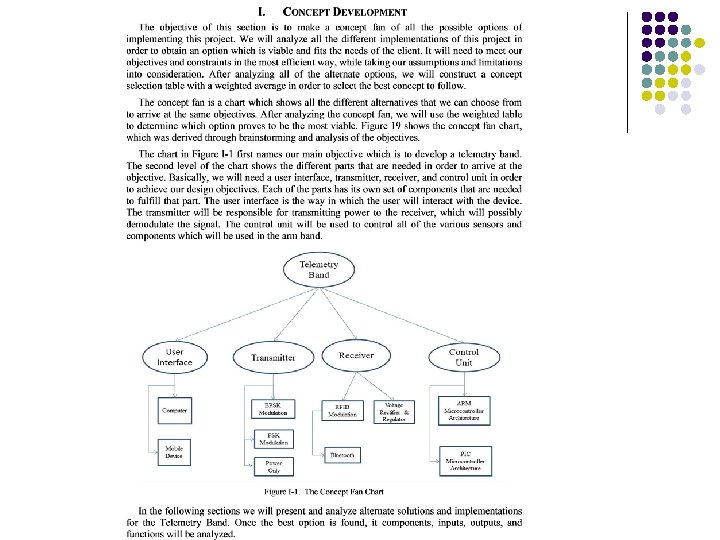
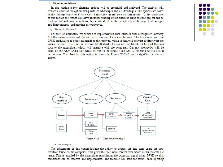
Concept Fan l The Concept Fan is a way of discovering alternative approaches to a problem when you have discarded all obvious solutions. It develops the principle of 'taking a step back' to get a broader viewpoint. Initially, the Concept Fan requires you to draw a circle in the middle of a large piece of paper. Write the problem you are trying to solve in the circle. To the right of it radiate lines representing possible solutions to the problem (concepts), see the diagram below: https: //www. mycoted. com/Concept_Fan
Concept Fan l It is possible that the ideas you have come up with are impractical or do not solve the problem. If this is the case, take a 'step back' for a broader analysis of the problem. Drawing a circle to the left of the first circle does this, writing the broader definition into this new circle and linking it with an arrow to show that it comes from the first circle, see diagram below: l Use this as a starting point to radiate out other ideas; if this does not give you an adequate amount of new concepts, you can take yet another step back (and another, and another…) https: //www. mycoted. com/Concept_Fan
Concept Fan
Concept Combination Table l A Concept Combination Table (also called morphology box) is a matrix of concept fragments organized by functions (each function forms a separate column) so that an integrated concept can be created by choosing any concept fragment for each function and combining them to complete the required functionality. https: //books. google. com/books? id=9 Zj. LBQAAQBAJ&pg=PA 114&lpg=PA 114&dq=concept+combination+table&source=bl&ots=ce. Bcn. U Ui 7 f&sig=Pi. CBZe. HApg. ZDjg. YV 2 Etc. YDbu. We. A&hl=en&sa=X&sqi=2&ved=0 ah. UKEwins. Oeq 4 b. TPAh. VJm. R 4 KHe. O 0 D 9 k. Q 6 AEIXDAM#v=o nepage&q=concept%20 combination%20 table&f=false
Concept Combination Table
Concept Combination Table
Concept Combination Table
Concept Selection
Concept Selection
End Product Description In this section you will describe: l. The constituent modules and their interrelationships l. The functionality of the product l. The functionality of the different modules l. Present the product specs
Black Box l In science, computing, and engineering, a black box is a device, system or object which can be viewed in terms of its inputs and outputs (or transfer characteristics), without any knowledge of its internal workings. Its implementation is "opaque" (black). Almost anything might be referred to as a black box: a transistor, an algorithm, or the human brain. https: //en. wikipedia. org/wiki/Black_box
Block Diagram l A block diagram is a diagram of a system in which the principal parts or functions are represented by blocks connected by lines that show the relationships of the blocks. They are heavily used in engineering in hardware design, electronic design, software design, and process flow diagrams. https: //en. wikipedia. org/wiki/Block_diagram http: //www. hobbyprojects. com/block_diagrams. html
End Product Description l l l To obtain the block diagram of a design we use a method based on levels We start with Level 0, which is the black box description of the project. We uncover Level 0 and see the Level 1 modules We continue this process until the step before placing components At each step we provide the modules' functions and interconnection specifications
Level 0 Equalizer Functionality This is the product description without knowledge of the internal blocks (black box)
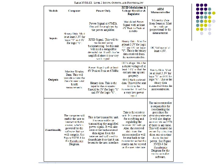
Level 1 Equalizer Functionality This a general Description of the internal blocks Only Pre-AMP table shown. Show a table for each block
Level 2 Automatic Level control (ALC)
Embedded Systems Require additional Information Pseudo Code or Flow Charts are required
Continue until the next step is to place components
Conventions l l Use buses (Thick lines) to represent several connecting lines that have common origin and destination Terminate the bus with an arrow head at the destination When information flow is bidirectional, place arrows at both ends of the bus When possible indicate the number of lines
Conventions l l At some level of detail all individual lines must show Images from: l l http: //file. scirp. org/Html/16401302_42760. htm and https: //en. wikipedia. org/wiki/ Control_system Remember, stop when the next step is placing components
In Summary l l Describe diagrams in paragraphs with local functionality tables slides (11 to 14) Repeat Functionality Tables l l Put level 0 functionality in one table Group all level 1 functionality tables in one table Repeat for all levels At the end of de section include the Technical Specs that you obtained before
Example
Diagrams and tables must be explained
Diagrams and tables must be explained
Diagrams and tables must be explained
Diagrams and tables must be explained, as in this case.
Diagrams and tables must be explained
Other Deliverables l l Power Point Presentation Final Report User Manual etc