CMOS OUTLINE Fanout Propagation delay CMOS power consumption


τ")


- Slides: 17
CMOS OUTLINE » Fan-out » Propagation delay » CMOS power consumption
Fan-In and Fan-Out • The fan-in of a gate is defined as the number of inputs to the gate. • The fan-out denotes the number of load gates N that are connected to the output of the driving gate. • Increasing the fan-out of a gate can affect its logic output levels.
The propagation delay • A very important measure of the performance of a digital system, such as a computer, is the maximum speed at which it is capable of operating.
The propagation delay tp of a gate defines how quickly it responds to a change at its input(s). It expresses the delay experienced by a signal when passing through a gate. It is measured between the 50% transition points of the input and output waveforms
The propagation delay • The tp. LH defines the response time of the gate for a low to high (or positive) output transition, while tp. HL refers to a high to low (or negative) transition. The propagation delay tp is defined as the average of the two.
The ring oscillator • A uniform way of measuring the tp of a gate, so that technologies can be judged on an equal footing, is desirable. • The de-facto standard circuit for delay measurement is the ring oscillator, which consists of an odd number of inverters connected in a circular chain • Typically, a ring oscillator needs a least five stages to be operational. The ring oscillator
Determining the Propagation Delay • The most fundamental way to compute delay is to develop a physical model of the circuit of interest, write a differential equation describing the output voltage as a function of input voltage and time, and solve the equation. • The solution of the differential equation is called the transient response, and the delay is the time when the output reaches VDD /2.
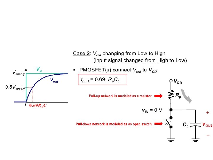
The propagation delays of the inverter.
The propagation delays of the inverter.
The time to reach the 50% point is easily computed as t = ln(2)τ = 0. 69τ
Power and Energy Consumption • The power consumption of a design determines how much energy is consumed per operation, and much heat the circuit dissipates where p(t) is the instantaneous power, isupply is the current being drawn from the supply voltage Vsupply over the interval t ∈ [0, T], and ipeak is the maximum value of isupply over that interval.
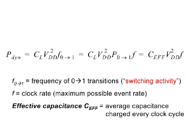
• The dissipation can further be decomposed into static and dynamic components. Where Istat is the current that flows between the supply rails in the absence of switching activity where f is the frequency at which the gate is switched. It follows that minimizing C is an effective means for reducing dynamic power dissipation
Dynamic Dissipation due to Charging and Discharging Capacitances
• If the gate is switched on and off f 0→ 1 times • per second, the power consumption equals f 0→ 1 represents the frequency of energy-consuming transitions, this is 0→ 1 transitions for static CMOS. If the input signals remain unchanged, no switching happens, and the dynamic power consumption is zero!
Reference books • CMOS VLSI Design A Circuits and Systems Perspective Fourth Edition, Neil H. E. Weste , David Money Harris. • VLSI Design and Tools : ดร. ธรยศ เวยงทอง • Sedra/Smith, Microelectronic Circuits, 6 th edition • Digital Integrated Circuits : A Design Perspective 2 Edition : Jan M. Rabaey, Anantha Chandrakasan, and Borivoje Nikolic