Processing the point cloud with Riscan Pro or


")


")


 List • • The list of reflectors is relative to each scan")


")


- Slides: 53
Processing the point cloud with Riscan. Pro or Riprofile Cyber. Mapping Lab UT-Dallas
Ri. Scan. Pro Overview of how to import and display scans
Table of Contents Window Start New Project Right Click SCANS New scan position
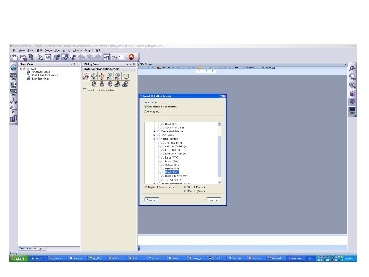
Import scans (. 3 dd format)
Select either 2 D or 3 D for viewing of point cloud
Point cloud with bounding box and scanner location
Ri. Scan. Pro Cleaning the image
Why Clean Up the Image? • A scanned image will include scan points of vegetation, extraneous points between the scanner and the outcrop, and extraneous points beyond the area of interest in the scene. – Points outside of the area of interest need to be removed to have a clean model. – Vegetation is notorious for creating poor models. The surface is very irregular and the Polyworks Model Builder does not handle this at all well. The removal of as much vegetation as possible without removing rock surface is advisable. • Both Polyworks and Ri. Scan. Pro can be used to clean the image. • Cleaning the model in Ri. Scan. Pro has the following advantages – The response of the computer is much faster in Ri. Scan. Pro than Polyworks – In Ri. Scan. Pro, points eliminated from the image are eliminated from the data set. Polyworks does not eliminate the deleted points but maintains them in the data set, thus there is no reduction in the size of the data set.
Ri. Scan. Pro Work Screen
Image Prior to Cleaning
Mouse Button Commands • • • The Ri. Scan. Pro and the Polyworks button commands are very similar. The screen shot below is taken from a Polyworks edit session. The left mouse button rotates the image. The point where the mouse is placed defines the pivot point for the rotation. The center mouse button moves the image without rotation. The right mouse button zooms the images. Holding down shift and the right mouse button rotates the image in the plane of the monitor screen but does not rotate the image in 3 D mode. Holding down shift and the center button forms a zoom window in Polyworks and in Ri. Scan. Pro it simply repeats the center button move command without the shift key.
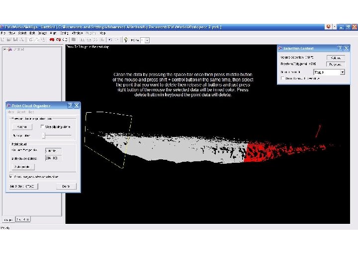
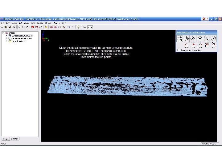
Point Deletion Process • • • Click the space bar to put the program into edit mode. A cross-hair cursor will appear Left click to select points defining a polygon which will surround the points that you wish to delete. Right click on the final point to close the selection action. Press the Del (Delete) key to complete the deletion. If you wish to abandon a selection you can click the space bar and return to navigate mode. If you wish to unselect points, click the Trash Can icon on the tool bar.
Ri. Scan. Pro Extracting Reflectors (Or, the secret to keeping your interpersonal relationships joyful)
Extraction of Reflectors • Polyworks has three methods of aligning scans that were made from different locations – Point cloud fitting algorithm – Control points using N selected points on the two scans, where N is optimally greater than 3, followed by point cloud fitting – Defined control point matching • The first method produces poor results. • The second method requires the operator to find common points on two scans. This can be difficult, frustrating, infuriating. • The third method is quick, easy, accurate, and leaves a smile on your face. • If at all possible, extract reflectors from the Ri. Scan point clouds and use them to align your scans in Polyworks.
Reflector Extraction Process • • Right click a scan in order to open the menu box Select Find Reflectors An option box will open. Un-select use auto-threshold. If you do not, you are likely to have numerous invalid reflectors. Start with 0. 85 for Threshold detection. If you find no reflectors, lower it. Try lowering in steps of 0. 1 You can name the reflectors (helpful in keeping things straight) and you need to indicate the starting reflector number. (Actually, in Polyworks the names and numbers are not used but you will go crazy trying to keep track of everything if you do not do this. ) Right Click to open menu
Tiepoint Editing Icons • When you open a tiepoint list, a new window will open. The icons at the top of the window are used to delete, export, and edit the tiepoints. Tiepoint control icons
Delete all points with small Pixels
Tie-point (Reflector) List • • The list of reflectors is relative to each scan position. Tie-points from multiple scans at the same scan position will be contained in the same TPL(SOCS) list. Note the Intensity column. Reflectors will have higher values than rock. Comments – A. Same scan but the reflector was identified as two reflectors, delete one – B and C. Same reflector in two different scans, average the results. Theoretically best done by using a weighted average.
Export the Reflectors to be used in Polyworks • • Click the Export tiepoint list icon to open the export screen. Export the Name, X, Y, and Z values. The names are not used in Polyworks but they are helpful in keeping things straight. Be sure that the Column Separator is comma, Be sure to give the exported file a descriptive name.
Exported Reflectors
Ri. Scan. Pro Export Point Cloud as ASCII File
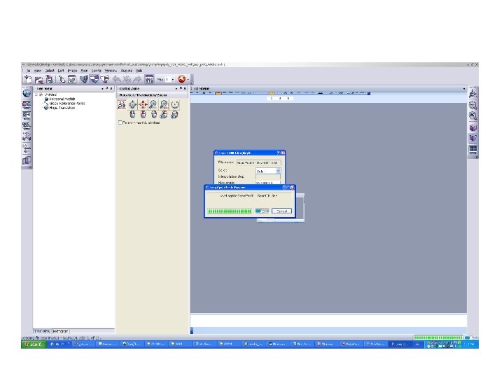
Export the Point Cloud as an ASCII File • • In order to have maximum flexibility in Polyworks to create the mesh, it is necessary to export the point cloud as an ASCII text file. If the cloud is imported into Polyworks as a. 3 dd file there is no ability to change the orientation of the mesh that is created. (There is debate at the moment about whether to use the. txt format described here or the. 3 dd format. ) Right click the individual scan and select Export in order to activate the menu.
Export the Point Cloud as an ASCII File • • Be sure to enter a file name that is descriptive. Be sure that the fields X, Y, Z, and Intensity are selected. None others should be selected an error will occur in Polyworks if they are. The Separator should be comma. The file will be saved as a. txt file.
Exported Data Format • The exported text file appears as below 15. 912, 11. 683, 7. 269, 0. 118 15. 805, 11. 605, 7. 199, 0. 125 15. 510, 11. 388, 7. 044, 0. 118 15. 159, 11. 130, 6. 864, 0. 110 15. 251, 11. 198, 6. 886, 0. 125 15. 296, 11. 231, 6. 886, 0. 118 15. 292, 11. 228, 6. 864, 0. 110 15. 321, 11. 250, 6. 857, 0. 133 15. 370, 11. 285, 6. 858, 0. 133 15. 368, 11. 284, 6. 837, 0. 141 15. 451, 11. 345, 6. 854, 0. 149 15. 578, 11. 438, 6. 890, 0. 157 16. 519, 12. 133, 7. 285, 0. 149 16. 497, 12. 117, 7. 253, 0. 141 16. 345, 12. 005, 7. 165, 0. 133 16. 237, 11. 926, 7. 096, 0. 141 16. 328, 11. 993, 7. 114, 0. 133
Building a mesh with Polyworks from text files
Overview of Polywork Interface Platform Polyworks prior Version 10 interface platform Polyworks Version 10 and after interface platform
Overview of Polyworks Modules Im. Compress: Im. Viewer: Im. Edit: Used to viewer to Used to edit reduce the display the 3 D models amount of models like filling triangles in the holes, models add and Im. Inspect: Im. Texture: Im. Merge: delete triangles Used to do Used to add Used to analysis for and merge one 3 D model maintain the or more like texture on scans and measureme the models create mesh nt and compare between two models Im. Align: Used to align two or more different scans
Poly. Works/Workspace Manager Basics Introducing the Workspace Manager The Poly. Works/Workspace Manager (WM for short) makes using Poly. Works modules and managing files easy. The WM manages a Poly. Works process from beginning to end, offering simple navigation tools between modules and easy process workflows for new users. The WM contains your input files and Poly. Works Projects, as well as files created as a result of the Poly. Works process. It also offers quick access to Poly. Works modules, Projects, or data. In short, the WM lets you: manage the contents of a workspace navigate within the Poly. Works process easily via the Wizard window contain your input files, your Projects and the Poly. Works-generated files document workspace objects by adding notes and images share information with your colleagues quickly
Polyworks Help Guides For more information, use help guides n the main polyworks window.
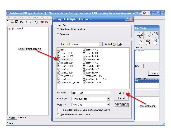
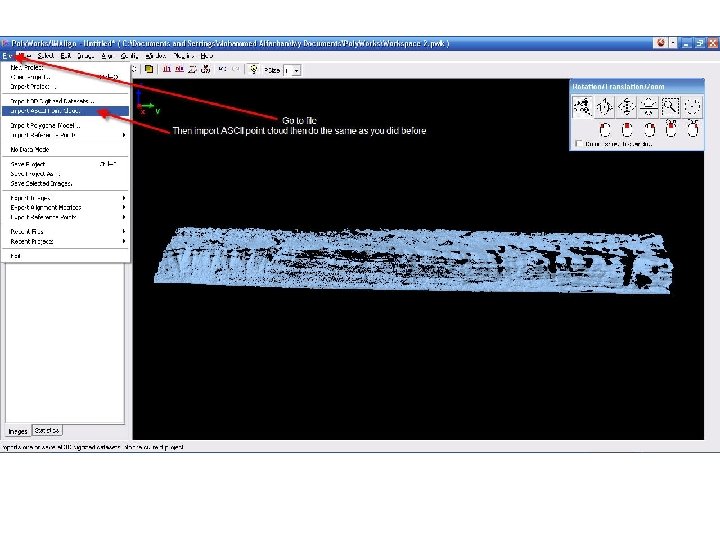
Importing ASCII File to Im. Align
Polyworks Workspace Open or create workspace window popup each time polyworks program startup. Create a new workspace for your work or select an existing workspace if you already have one. For quick work or test that you don’t need to save any work you may select cancel.
Import Scan Data to Im. Align
You should get it from here for the first time then it will appear in the recent formats
Importing 3 DD File to Im. Align
Import Scan Data to Im. Align (3 DD Format)
you can select Multiple scans in one time
Select OK
Change from 75 to 89
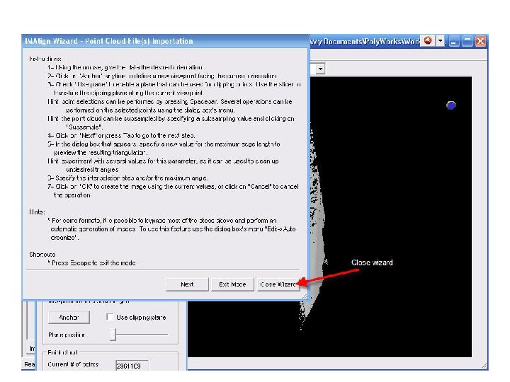
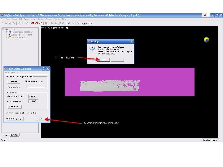
Close Wizard
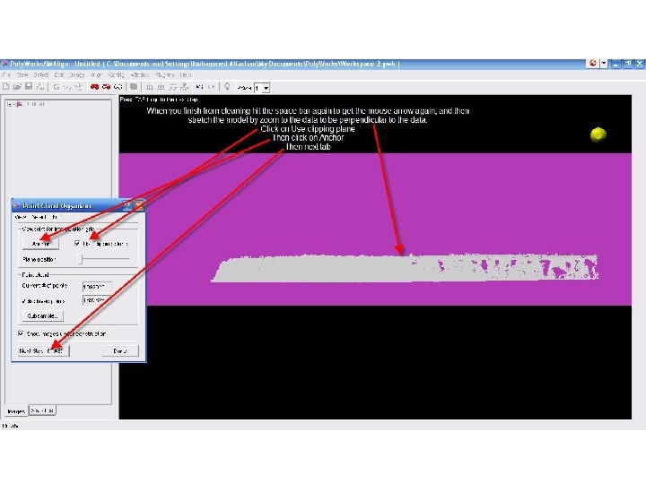
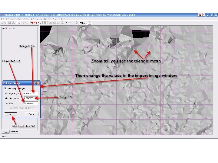
1 - Change these values Each model has different value 3 - Click OK when you finish 2 - Click update then zoom to the outcrop to see the changes
Focus distance A text box that specifies a distance from the scan origin. This distance is used for two purposes. At focus distance it identifies a circular zone of data points in the middle of the first range. Its value is then doubled to calculate the upper limit of the first range. Note that each time a value is specified, the Step at focus value is automatically calculated. Step at focus A text box that specifies the point-to-point spacing calculated by IMAlign at the Focus distance. Since it is calculated in the middle of the first range, it provides a good average interpolation step for that range. Its value is doubled for each subsequent range, and used as the interpolation step for the range when it is larger than the Min. interpolation step. You may also enter your own base value in the text box. Max edge length A text box that specifies the base value used to limit the maximum triangle edge length for each range. The default value is 1000. It is recommended to change this value. This value is used for the first range and doubled for each subsequent range. Note that to see the bridging in the 3 D rendering window, the drawing type of the Static display mode should be set to Flat (View > Image Default Static > Flat).
Main File
Subdivided files and this case there are 70 files