ONF CIM Introduction to the Model 1 Presentation


- Slides: 56
ONF CIM Introduction to the Model 1
Presentation Goals • By the end of this presentation you should be able to understand • Why we use models • How to use the model tooling • How to read a model diagram • How the core model can be extended for specific protocols and features • If you think of anything during the presentation that you think we have missed, note it for the Q&A section
Why We Model 3
We model to create a common language • Formal modelling provides a framework where understanding about managing networks can • • be stored It provides a common language for network management domain experts to use when they interact It allows consistency across protocol and feature management representations, simplifying understanding of the functionality It stops the formation of semantic silos which would hinder implementations interacting It allows the generation of consistent artefacts in languages like Yang and JSON • And we use UML because a graphical modelling language highlights the underlying patterns
The Design Goals of the ONF CIM are • To provide a well defined representation of managed network functionality • To leverage industry best-practices, patterns, tools… where appropriate • To provide a practical, useful and scalable modeling environment • To produce a lightweight (“slim”) core model, that is technology and technique agnostic • To promote reuse and extension of the CIM model by having a modular architecture
Patterns allow us to reuse experience gained • It’s easier to reuse a cake recipe than a cake (reverse engineering is hard – how long was it baked for and at what temperature ? – the result is likely a guess) • Model structures that were useful in other models can be identified and reused • Patterns highlight deeper understandings and insight gained – this is where the real value is, not in ‘throwing boxes on a diagram’ • For example - if we were to design a new network protocol model, what learnings from existing protocol models would we use ? What things would we avoid (anti-patterns) ?
How we model – UML and tooling 7
The ONF CIM uses a form of the industry standard UML modelling language • UML is a graphical modelling language • There are many books and online references that can be used to understand UML, so it won’t be covered in detail here • The document ONF TR-514 “UML Modeling Guidelines” details how UML is used for the ONF CIM models
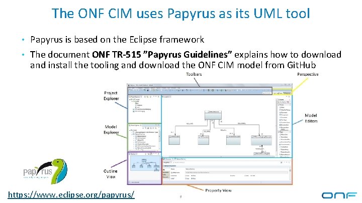
The ONF CIM uses Papyrus as its UML tool • Papyrus is based on the Eclipse framework • The document ONF TR-515 ”Papyrus Guidelines” explains how to download and install the tooling and download the ONF CIM model from Git. Hub https: //www. eclipse. org/papyrus/ 9
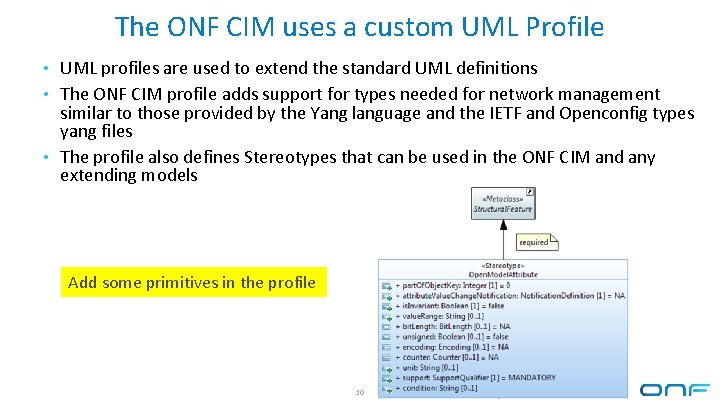
The ONF CIM uses a custom UML Profile • UML profiles are used to extend the standard UML definitions • The ONF CIM profile adds support for types needed for network management similar to those provided by the Yang language and the IETF and Openconfig types yang files • The profile also defines Stereotypes that can be used in the ONF CIM and any extending models Add some primitives in the profile 10
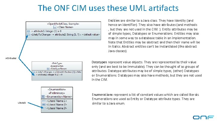
The ONF CIM uses these UML artifacts Entities are similar to a Java class. They have identity (and hence an identifier). They also have attributes (and methods , but they are not used in the CIM. ). Entity attributes may be of simple types, Datatypes or Enumerations. Entities may also map in some way to a database table in an implementation. Note that Entities may be abstract and then their name will be in italics. Abstract entities can’t be instantiated (like abstract Java classes). Attributes Datatypes represent value objects. They are represented by their value only (and are best to be immutable). They can be thought of as groups of attributes. Datatype attributes may be of simple types, (other) Datatypes or Enumerations. Datatypes may also have methods, but they are not used in the CIM. Literals Enumerations represent a list of constant values which are called literals. Enumerations are used as Entity or Datatype attribute types. They are similar to a Java enum.
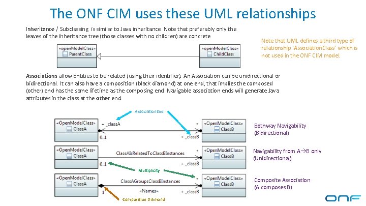
The ONF CIM uses these UML relationships Inheritance / Subclassing is similar to Java inheritance. Note that preferably only the leaves of the inheritance tree (those classes with no children) are concrete Note that UML defines a third type of relationship ‘Association. Class’ which is not used in the ONF CIM model. Associations allow Entities to be related (using their identifier). An Association can be unidirectional or bidirectional. It can also have a composition (black diamond) at one end, that implies the composed (other) end has the same lifetime as the composing end. Navigable association ends will generate Java attributes in the class at the other end. Association. End Bothway Navigability (Bidirectional) Navigability from A B only (Unidirectional) Multiplicity Composite Association (A composes B) Composition Diamond
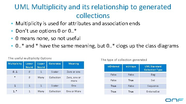
UML Multiplicity and its relationship to generated collections • Multiplicity is used for attributes and association ends • Don’t use options 0 or 0. . * • 0 means none, so not useful • 0. . * and * have the same meaning, but 0. . * clogs up the class diagrams The useful multiplicity Options Multiplicity Lower Bound Upper Bound Generates Meaning 0. . 1 0 1 Scalar Zero or one * 0 Many Collection Zero, one or more 1 1 1 Scalar 1. . * 1 Many Collection The type of collection generated is. Ordered is. Unique UML Standard Collection Type False Bag False True Set One True False Sequence One or More True Ordered. Set
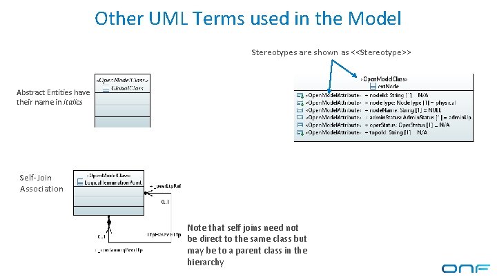
Other UML Terms used in the Model Stereotypes are shown as <<Stereotype>> Abstract Entities have their name in italics Self-Join Association Note that self joins need not be direct to the same class but may be to a parent class in the hierarchy
Every artifact in the ONF CIM is given a lifecycle stereotype The stereotype indicates where the artifact is in the design process and its level of maturity 15
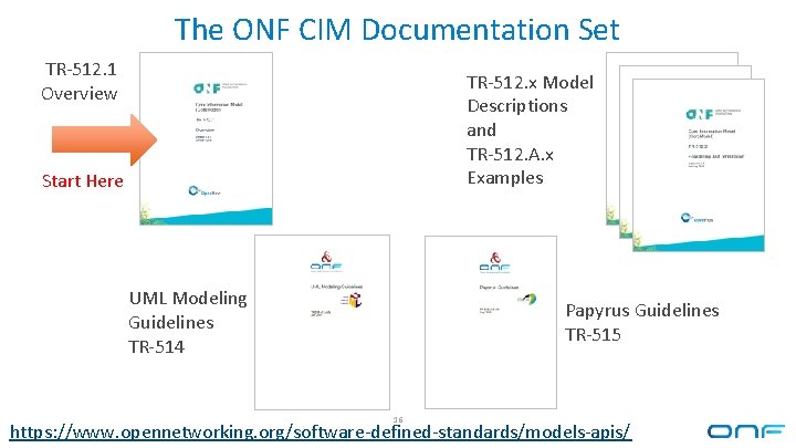
The ONF CIM Documentation Set TR-512. 1 Overview TR-512. x Model Descriptions and TR-512. A. x Examples Start Here UML Modeling Guidelines TR-514 Papyrus Guidelines TR-515 16 https: //www. opennetworking. org/software-defined-standards/models-apis/
The Common Model Framework Design 17
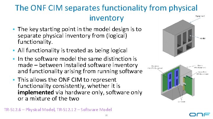
The ONF CIM separates functionality from physical inventory • The key starting point in the model design is to separate physical inventory from (logical) functionality. • All functionality is treated as being logical • In the software model the same distinction is made – between installed software inventory and functionality arising from running software • This allows the ONF CIM to represent functionality consistently, whether it is implemented via hardware only, software only or a mixture of the two TR-512. 6 – Physical Model, TR-512. 12 – Software Model 18
Processing and Transport Functions • It is useful to categorize the parts of a network in terms of the type of • • functions that they provide. Two key function types are processing and transport of information. A Processing Function processes (transforms) information without transporting it. This also includes creating and terminating information. A Transport Function transports (existing) information without changing it Most higher level functions do both transport and processing to varying degrees, but can be broken down into a combination of these two primitives If a function does mainly information processing, the very small portion of transport functionality can often be ignored and if doing mainly information transport, the processing function can often be ignored 19
Operational and Knowledge Layers • In networking, common ‘building blocks’ are often repeatedly assembled to • • implement functionality but with varying configurations Separating out the invariant mechanisms from the varying configurations allows a model implementation to dramatically reduce the stored data at the expense of a slightly more complex model. The varying classes form the operational layer and the invariant classes which we call Specification classes, form the knowledge layer In effect, the ONF CIM model defines classes that can be used to build a library of specification information This model layering also allows a greater level of detail to be stored than would be practical without use of this pattern 20
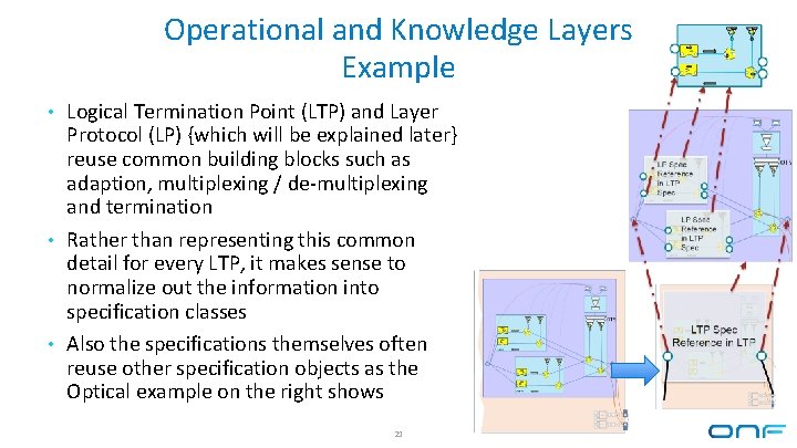
Operational and Knowledge Layers Example • Logical Termination Point (LTP) and Layer Protocol (LP) {which will be explained later} reuse common building blocks such as adaption, multiplexing / de-multiplexing and termination • Rather than representing this common detail for every LTP, it makes sense to normalize out the information into specification classes • Also the specifications themselves often reuse other specification objects as the Optical example on the right shows 21
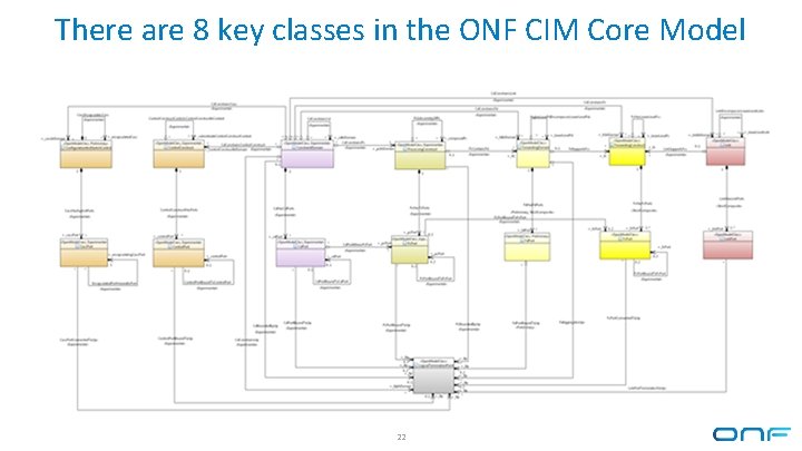
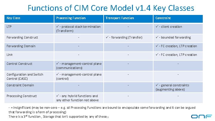
There are 8 key classes in the ONF CIM Core Model 22
Functions of CIM Core Model v 1. 4 Key Classes Key Class Processing Function LTP - protocol stack termination (Transform) Transport Function - Constraint - client creation Forwarding Construct - Forwarding Domain - - - FC creation, LTP creation Link - - - FC creation, LTP creation Control Construct - management-control plane (communications) - - Configuration and Switch Control (CASC) - management-control plane (control) - - Constraint Domain Processing Construct - any hybrid functions and any other function not above - forwarding (Transfer) - - bounded forwarding - general constraints (augmenting above) - - = insignificant (may be non-zero – e. g. all Processing Functions are bound to encapsulate some forwarding and it can be argued that forwarding is a form of processing) There is a 3 rd function , Storage that isn’t supported by any of these 23
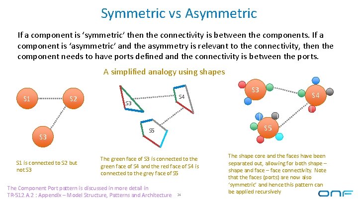
Symmetric vs Asymmetric If a component is ‘symmetric’ then the connectivity is between the components. If a component is ‘asymmetric’ and the asymmetry is relevant to the connectivity, then the component needs to have ports defined and the connectivity is between the ports. A simplified analogy using shapes S 1 S 2 S 3 S 1 is connected to S 2 but not S 3 S 4 S 5 The green face of S 3 is connected to the green face of S 4 and the red face of S 4 is connected to the grey face of S 5 The Component Port pattern is discussed in more detail in TR-512. A. 2 : Appendix – Model Structure, Patterns and Architecture S 3 24 The shape core and the faces have been separated out, allowing for both shape – shape and face – face connectivity. Note that the faces (ports) are now also ‘symmetric’ and hence this pattern can be applied recursively
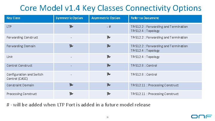
Core Model v 1. 4 Key Classes Connectivity Options Key Class LTP Symmetric Option Asymmetric Option Refer to Document -# TR-512. 2 : Forwarding and Termination TR-512. 4 : Topology - TR-512. 2 : Forwarding and Termination TR-512. 4 : Topology Link - TR-512. 4 : Topology Control Construct - TR-512. 8 : Control Configuration and Switch Control (CASC) - TR-512. 8 : Control Constraint Domain TR-512. 11 : Processing Construct Forwarding Domain # - will be added when LTP Port is added in a future model release 25
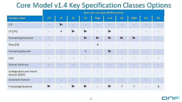
Core Model v 1. 4 Key Specification Classes Options Spec can use Spec (R=Recursive) Key Spec Class LTP LP FC FD Flow Link CC CASC CD PC LTP - - - - - LP [LTP] - R - - - Forwarding Construct - - - Flow [FC] - Forwarding Domain - - - R - - - Link - - - - - Control Construct - - - - - R Configuration and Switch Control (CASC) Constraint Domain Processing Construct - - - - ? ? - R 26
A Note on the Following Definitions • They have been deliberately simplified for clarity • All the concepts represent network management abstractions of the functions, not the actual functions 27
Logical Termination Point (LTP) and Layer Protocol (LP) • LTP provides an interconnection point in the model that allows the seven key classes and their ports to be interconnected without needing a large number of associations (n 2 = 49) • LTP also provides a common place to represent the termination of protocol layer information and the adaption between protocol layers • LP represents protocol layer specific information within the LTP 28
LTP and LP Example 29
Forwarding Construct (FC) • Transports information (forwarding) between its ports • A Forwarding Construct may have two ports (point-point) or more than two (to represent broadcast forwarding) and each port can be associated to a Logical Termination Point • A FC has ports (Fc. Port) which take roles relevant to how the Forwarding Construct transports information • Note that a FC is NOT the actual flow of information 30
Forwarding Construct Example 31
Forwarding Domain (FD) • A Forwarding Domain constrains transport of information by constraining enclosed Forwarding Constructs, Links and other Forwarding. Domains, by limiting their extent and connections to LTP • A Forwarding Domain may have many ports, each of which can be associated to a Logical Termination Point • For example, a Forwarding Domain could enforce that certain Forwarding Constructs only lie ‘within’ the FD • A FD can be partitioned into two or more FD connected via one or more Links 32
Link • A Link constrains the creation of Forwarding Constructs between two or more Forwarding. Domains (FD), by associating a set of LTP on one FD with an equivalent set of LTP on another FD. • A Link may have two ports (point-point) or more than two (to represent broadcast adjacencies) and each port can be associated to a Logical Termination Point • Like the FC, the Link has ports (Link. Port) which take roles relevant to the constraints on flows offered by the Link (e. g. , Root role or leaf role for a Link that has a constrained Tree configuration). • Note that a Link doesn’t actually forward information 33
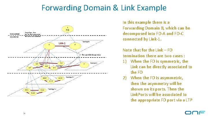
Forwarding Domain & Link Example FD Link-1 In this example there is a Forwarding Domain B, which can be decomposed into FD-A and FD-C connected by Link-1. Note that for the Link – FD termination there are two cases : 1) When the FD is symmetric, the Link can be directly associated to the FD 2) When the FD is asymmetric, then the asymmetry will be shown on its ports. Then the Link. Ports will be associated to the appropriate FD port via a LTP 34
Constraint Domain (CD) • A Constraint Domain is a general grouping, scoping and constraining concept. • It is used to group network functionality and then constraints can be applied to the group if required (the constraint model will be added to the ONF CIM in a future release) • Constraint Domain doesn’t represent any transport or processing functionality • Constraint Domains can be related, they can overlap and they don't need to form a hierarchy. • Note that there is some overlap with other CIM model artifacts that also do some specialized constraining, such as Forwarding Domain 35
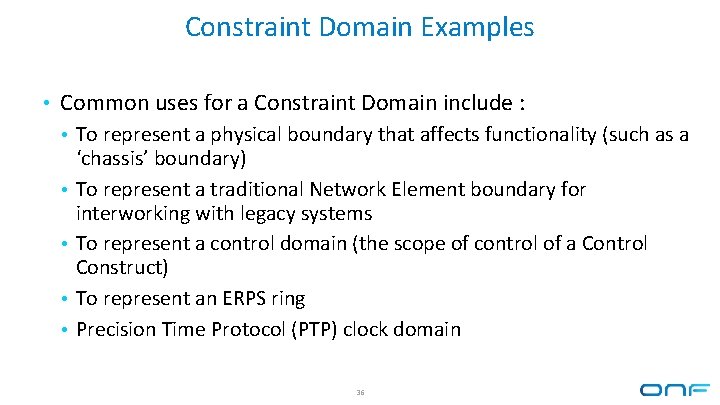
Constraint Domain Examples • Common uses for a Constraint Domain include : • To represent a physical boundary that affects functionality (such as a • • ‘chassis’ boundary) To represent a traditional Network Element boundary for interworking with legacy systems To represent a control domain (the scope of control of a Control Construct) To represent an ERPS ring Precision Time Protocol (PTP) clock domain 36
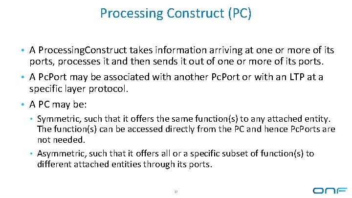
Processing Construct (PC) • A Processing. Construct takes information arriving at one or more of its ports, processes it and then sends it out of one or more of its ports. • A Pc. Port may be associated with another Pc. Port or with an LTP at a specific layer protocol. • A PC may be: • Symmetric, such that it offers the same function(s) to any attached entity. The function(s) can be accessed directly from the PC and hence Pc. Ports are not needed. • Asymmetric, such that it offers all or a specific subset of function(s) to different attached entities through its ports. 37
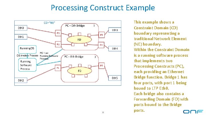
Processing Construct Example 1 2 38 This example shows a Constraint Domain (CD) boundary representing a traditional Network Element (NE) boundary. Within the Constraint Domain is a running software process that implements two Processing Constructs (PC), each providing an Ethernet Bridge function. Bridge 1 has four ports, with port 1 being bound to LTP Eth 0. Each bridge also contains a Forwarding Domain (FD) with ports bound to the Bridge ports.
Control Construct (CC) • A Control Construct processes information to control other network functions (such as Processing Constructs, Forwarding Constructs etc. ) • The ONF CIM can represent generic management and control networks : • By representing the binding between Control Constructs via their ports and the roles at each end of the binding • By the nesting of Control Constructs in a Constraint Domain that is controlled by another Control Construct (in this case, the Constraint Domain is playing the role of a control domain) 39
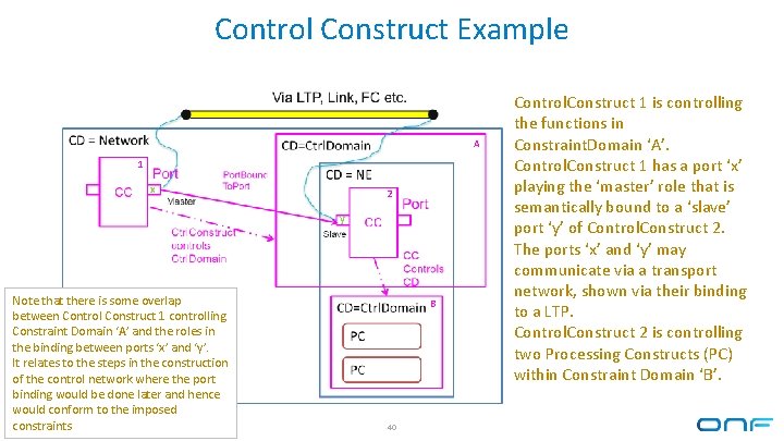
Control Construct Example A 1 x 2 y Note that there is some overlap between Control Construct 1 controlling Constraint Domain ‘A’ and the roles in the binding between ports ‘x’ and ‘y’. It relates to the steps in the construction of the control network where the port binding would be done later and hence would conform to the imposed constraints B 40 Control. Construct 1 is controlling the functions in Constraint. Domain ‘A’. Control. Construct 1 has a port ‘x’ playing the ‘master’ role that is semantically bound to a ‘slave’ port ‘y’ of Control. Construct 2. The ports ‘x’ and ‘y’ may communicate via a transport network, shown via their binding to a LTP. Control. Construct 2 is controlling two Processing Constructs (PC) within Constraint Domain ‘B’.
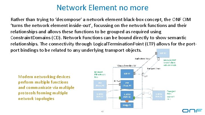
Network Element no more Rather than trying to ‘decompose’ a network element black-box concept, the ONF CIM ‘turns the network element inside-out’, focussing on the network functions and their relationships and allows these functions to be grouped as required using Constraint. Domains (CD). Network Functions can be bound directly to show semantic relationships. The connectivity through Logical. Termination. Point (LTP) allows for the port bindings to be related to any underlying transport objects. Modern networking devices perform multiple functions and communicate via multiple protocols forming multiple network topologies 41
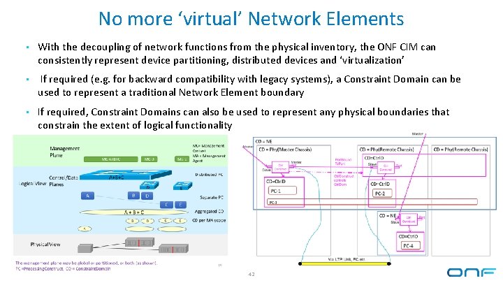
No more ‘virtual’ Network Elements • With the decoupling of network functions from the physical inventory, the ONF CIM can consistently represent device partitioning, distributed devices and ‘virtualization’ • If required (e. g. for backward compatibility with legacy systems), a Constraint Domain can be used to represent a traditional Network Element boundary • If required, Constraint Domains can also be used to represent any physical boundaries that constrain the extent of logical functionality 42
More Advanced Topics 43
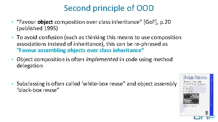
Second principle of OOD • “Favour object composition over class inheritance” [Go. F], p. 20 (published 1995) • To avoid confusion (such as thinking this means to use composition associations instead of inheritance), this can be re-phrased as “Favour assembling objects over class inheritance” • Object composition is often implemented in code using method delegation • Subclassing is often called ‘white-box reuse” and object assembly ‘black-box reuse”
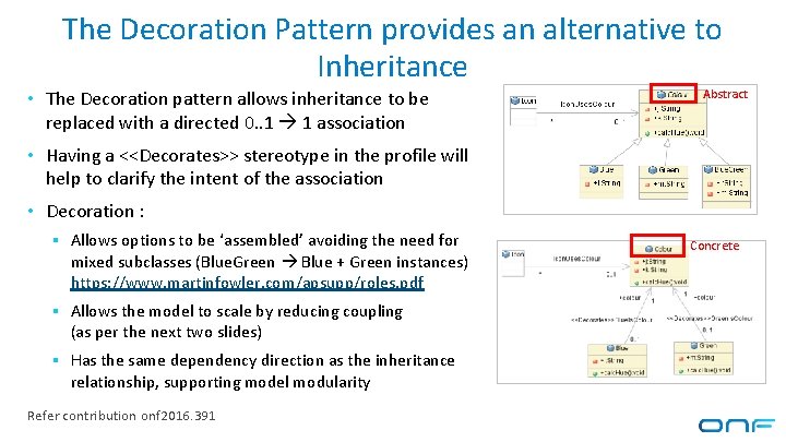
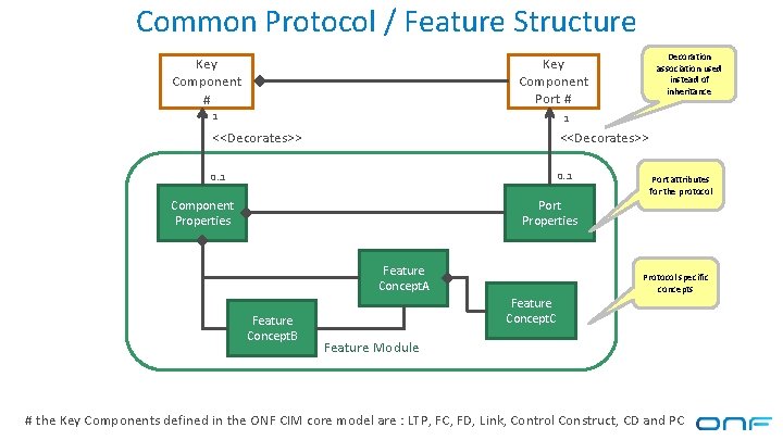
The Decoration Pattern provides an alternative to Inheritance • The Decoration pattern allows inheritance to be Abstract replaced with a directed 0. . 1 1 association • Having a <<Decorates>> stereotype in the profile will help to clarify the intent of the association • Decoration : § Allows options to be ‘assembled’ avoiding the need for mixed subclasses (Blue. Green Blue + Green instances) https: //www. martinfowler. com/apsupp/roles. pdf § Allows the model to scale by reducing coupling (as per the next two slides) § Has the same dependency direction as the inheritance relationship, supporting model modularity Refer contribution onf 2016. 391 Concrete
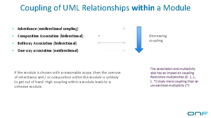
Coupling of UML Relationships within a Module • Inheritance (unidirectional coupling) • Composition Association (bidirectional) • Bothway Association (bidirectional) • One way association (unidirectional) If the module is chosen with a reasonable scope, then the overuse of inheritance and / or composition within the module is unlikely to get out of hand. High coupling within a module leads to a cohesive module. Decreasing coupling The association end multiplicity also has an impact on coupling. Restrictive multiplicities (0. . 1, 1, 1. . *) imply more coupling than an unrestricted multiplicity (*)
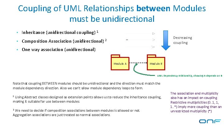
Coupling of UML Relationships between Modules must be unidirectional • Inheritance (unidirectional coupling) 1 Decreasing coupling • Composition Association (unidirectional) 2 • One way association (unidirectional) Module A Module B UML Dependency relationship, showing A depends on B Note that coupling BETWEEN modules should be unidirectional and the direction must match the module dependency direction. Also we can’t allow module dependency loops to form. 1 Using Abstract classes designed as extension points allows us to reduce the inheritance coupling, making it suitable for use between modules. 2 We need to decide if composition associations between modules is allowed or not. Aggregation associations are just treated as normal associations. The association end multiplicity also has an impact on coupling. Restrictive multiplicities (0. . 1, 1, 1. . *) imply more coupling than an unrestricted multiplicity (*)
The ONF CIM defines the Minimum Required Coupling • The ONF CIM defines a model suitable to be used to define a management interface • The proposed dependency rules can be thought of as defining a MINIMUM set of required dependencies, that allow these interface definitions to grow and be maintained • It would be a folly to define a maximally dependent model and have implementers needing to arbitrarily chose which dependencies to remove • An implementation can add reverse dependencies as they retrieve data via the management interface and then discard any surplus dependencies when writing back to the management interface. For example in a relational database, foreign key references are created based on association multiplicity which may not match the defined association navigability – perhaps even resulting in a dependency reversal
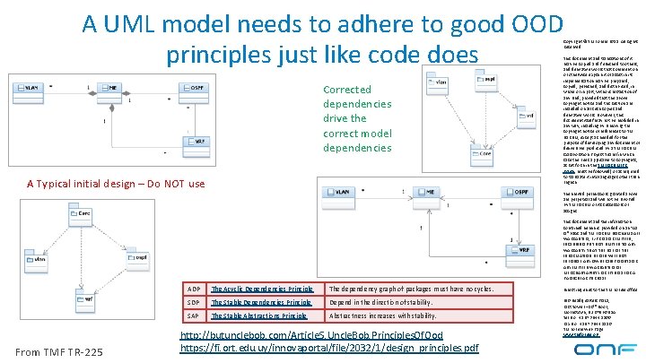
A UML model needs to adhere to good OOD principles just like code does Corrected dependencies drive the correct model dependencies A Typical initial design – Do NOT use From TMF TR-225 ADP The Acyclic Dependencies Principle The dependency graph of packages must have no cycles. SDP The Stable Dependencies Principle Depend in the direction of stability. SAP The Stable Abstractions Principle Abstractness increases with stability. http: //butunclebob. com/Article. S. Uncle. Bob. Principles. Of. Ood https: //fi. ort. edu. uy/innovaportal/file/2032/1/design_principles. pdf Copyright © TM Forum 2015. All Rights Reserved. This document and translations of it may be copied and furnished to others, and derivative works that comment on or otherwise explain it or assist in its implementation may be prepared, copied, published, and distributed, in whole or in part, without restriction of any kind, provided that the above copyright notice and this section are included on all such copies and derivative works. However, this document itself may not be modified in any way, including by removing the copyright notice or references to TM FORUM, except as needed for the purpose of developing any document or deliverable produced by a TM FORUM Collaboration Project Team (in which case the rules applicable to copyrights, as set forth in the TM FORUM IPR Policy, must be followed) or as required to translate it into languages other than English. The limited permissions granted above are perpetual and will not be revoked by TM FORUM or its successors or assigns. This document and the information contained herein is provided on an “AS IS” basis and TM FORUM DISCLAIMS ALL WARRANTIES, EXPRESS OR IMPLIED, INCLUDING BUT NOT LIMITED TO ANY WARRANTY THAT THE USE OF THE INFORMATION HEREIN WILL NOT INFRINGE ANY OWNERSHIP RIGHTS OR ANY IMPLIED WARRANTIES OF MERCHANTABILITY OR FITNESS FOR A PARTICULAR PURPOSE. Direct inquiries to the TM Forum office: 240 Headquarters Plaza, East Tower – 10 th Floor, Morristown, NJ 07960 USA Tel No. +1 973 944 5100 Fax No. +1 973 944 5110 TM Forum Web Page: www. tmforum. org
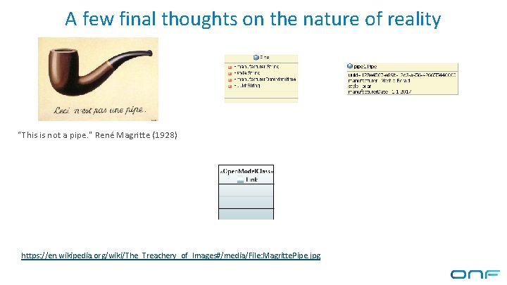
A few final thoughts on the nature of reality “This is not a pipe. " René Magritte (1928) https: //en. wikipedia. org/wiki/The_Treachery_of_Images#/media/File: Magritte. Pipe. jpg
Extending the CIM Model 51
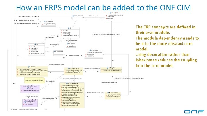
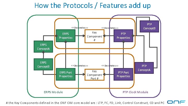
How an ERPS model can be added to the ONF CIM The ERP concepts are defined in their own module. The module dependency needs to be into the more abstract core model. Using decoration rather than inheritance reduces the coupling into the core model. 52
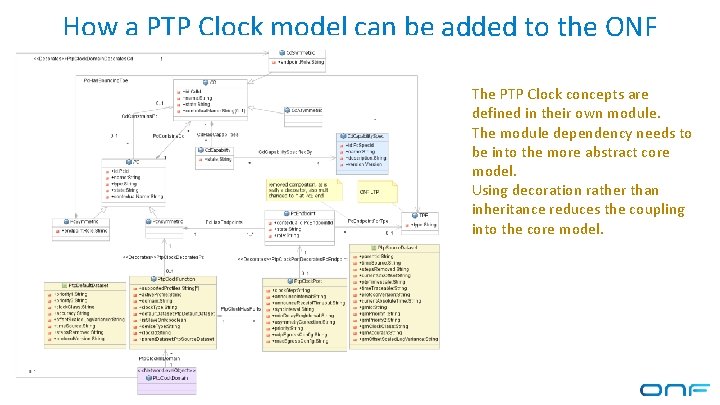
How a PTP Clock model can be added to the ONF CIM The PTP Clock concepts are defined in their own module. The module dependency needs to be into the more abstract core model. Using decoration rather than inheritance reduces the coupling into the core model. 53
Common Protocol / Feature Structure Decoration association used instead of inheritance Key Component Port # Key Component # 1 1 <<Decorates>> 0. . 1 Component Properties Port attributes for the protocol Port Properties Feature Concept. A Feature Concept. B Protocol specific concepts Feature Concept. C Feature Module # the Key Components defined in the ONF CIM core model are : LTP, FC, FD, Link, Control Construct, CD and PC
How the Protocols / Features add up <<Decorates>> ERPS Properties PTP Concept. B <<Decorates>> Key Component # PTP Properties ERPS Concept. A ERPS Concept. B <<Decorates>> ERPS Port Properties ERPS Module <<Decorates>> Key Component Port # PTP Port Properties PTP Concept. A PTP Clock Module # the Key Components defined in the ONF CIM core model are : LTP, FC, FD, Link, Control Construct, CD and PC
Q&A 56