Advancements in ONF Transport API for Orchestration of


- Slides: 20

Advancements in ONF Transport API for Orchestration of Multi-layer Connectivity Service Andrea Mazzini, Nokia Karthik Sethuraman, NEC September 2019 *animated slides

ONF Transport API (TAPI): Functional Architecture Industry Adoption: Functional Interface solution that best fulfills conflicting requirements of stability (future proof, interoperability) & flexibility/agility (technology evolution) Application NE NE SDN NE Controller NE Transport API or Other NBIs Topology Service Connectivity Service OAM Service Path Computation Service Virtual Network Service Shared Network Information Context Transport API or Other SBIs Network NEElements 2 SDN NE Controller NE Equipment Inventory Service Notification Service

OIF Transport API Interop Demo (2014, 2016, 2018) Test Carriers OSS/App/Orchestrator TAPI Agent Transport API Multi-Domain Controller Transport API Common Abstraction model TAPI Agent Multi-Domain Controller Transport API Technology, Vendor Specific models TAPI Agent Domain Controller Test Vendors 3

MEF: Lifecycle Service Orchestration Reference Architecture (LSO RA) MEF Common Resource Model ONF TAPI Model 4

MEF: Service Provider, Operators, ICM Domains, UNI, ENNI, INNI (1) Service Provider Partner Operator ICM Domain ICM UNI OLS Domain ICM Domain ENNI 5 ICM Domain INNI UNI

LEGATO MEF: Service Provider, Operators, ICM Domains, UNI, ENNI, INNI (3) Create L 1 VC INTERLUDE Service Orchestration Functionality (SOF), SP Domain Create L 1 OVC SOF, Partner Operator Domain PRESTO SOF, Operator Domain Create Connectivity Service ICM Infrastructure Control & Mng (ICM) Create Connectivity Service Open Line System ICM Node OLS Node UNI E-NNI Node I-NNI 6 UNI

MEF: Layer 1 Service across different Operators & Management Domains managed object classes at Service level (appearing at Legato, Interlude Management IRPs) ONF TAPI managed object classes at Resource level (appearing at Presto for provisioning purposes) ONF TAPI managed object classes at Resource level (appearing at Presto for discovery purposes, e. g. topology) L 1 VC (the end-to-end Layer 1 Service) Connectivity. Service Connection Node UNI OLS Node E-NNI CEP NEP L 1 Uni. NResource SIP L 1 Connectivity End. Point. Resource CSEP SIP CSEP L 1 Service. Level. Specification L 1 OVC L 1 Connectivity Resource MEF Resource managed object classes augmenting TAPI Service Interface Point NEP Node Edge Point Connectivity Service End Point CEP Connection End Point L 1 Enni. N Resource Node I-NNI CEP CEP NEP NEP SIP SIP CSEP EVC up MEP OVC Up MEP UNI Down MEP EVC MIP OVC Up MEP ENNI Down MEP L 1 Inni. N Resource UNI

ONF ODTN (Open Disaggregated Transport) Architecture With OLS Controller TAPI ONOS TAPI OLS Controller Has topology Open. Config TRN MUX WSS AMP Open Line System (OLS) 8 WSS MUX TRN

Operator Domain Topology SOF-ICM TAPI Context (LSO Presto) Operator SOF view 100 G Operator ICM View UNI 100 G TPD 1 TPD 2 E-NNI OLS Node 100 G TPD 3 100 G ICM-OLS TAPI Context OLS View Abbreviations TPD – Transponder Node RDM – ROADM Node UNI – User-Network Interface NNI – Network-Network Interface DSR – Digital Signal Rate OTSi – Optical Tributary Signal OTSi. A – OTSi Assembly MC – Media Channel Logical Termination Points shown Service Interface Point Node Edge Point (Network Edge) Node Edge Point (Network Internal) Connectivity Service End Point I-NNI 1 RDM 1 I-NNI 3 I-NNI 2 RDM 3 OLS Domain 9 RDM 4 RDM 5 Connection / Connection End Point Photonic Connection Photonic Media Channel

Operator Domain Connectivity Service & Resources(1) SOF-ICM TAPI Context (LSO Presto) DSR Connectivity Service 1 (100 G) Operator SOF view DSR 1 100 G OTSi. A 1 200 G 100 G OTSi 1 -1 OTSi 1 -2 Operator ICM View UNI 100 G TPD 1 TPD 2 OLS Node 100 G OTSi-MC 1 OTSi 1 -1 OTSi-MC 2 OTSi 1 -2 100 G E-NNI 100 G TPD 3 100 G ICM-OLS TAPI Context OLS View Abbreviations TPD – Transponder Node RDM – ROADM Node UNI – User-Network Interface NNI – Network-Network Interface DSR – Digital Signal Rate OTSi – Optical Tributary Signal OTSi. A – OTSi Assembly MC – Media Channel Photonic Connectivity Service 1 Logical Termination Points shown Service Interface Point Node Edge Point (Network Edge) Node Edge Point (Network Internal) Connectivity Service End Point I-NNI 1 OTSi-MC 2 RDM 1 I-NNI 3 I-NNI 2 RDM 3 OLS Domain 10 RDM 4 RDM 5 Connection / Connection End Point Photonic Connection Photonic Media Channel

Operator Domain Connectivity Service & Resources (2) SOF-ICM TAPI Context (LSO Presto) DSR Connectivity Service 1 (100 G) DSR Connectivity Service 2 (100 G) Operator SOF view DSR 2 100 G DSR 1 100 G OTSi. A 1 200 G 100 G OTSi 1 -1 OTSi 1 -2 Operator ICM View UNI 100 G TPD 1 TPD 2 OLS Node 100 G OTSi-MC 1 OTSi 1 -1 OTSi-MC 2 OTSi 1 -2 100 G E-NNI 100 G TPD 3 100 G ICM-OLS TAPI Context OLS View Abbreviations TPD – Transponder Node RDM – ROADM Node UNI – User-Network Interface NNI – Network-Network Interface DSR – Digital Signal Rate OTSi – Optical Tributary Signal OTSi. A – OTSi Assembly MC – Media Channel Photonic Connectivity Service 1 Logical Termination Points shown Service Interface Point Node Edge Point (Network Edge) Node Edge Point (Network Internal) Connectivity Service End Point I-NNI 1 OTSi-MC 2 RDM 1 I-NNI 3 I-NNI 2 RDM 3 OLS Domain 11 RDM 4 RDM 5 Connection / Connection End Point Photonic Connection Photonic Media Channel

Operator Domain Connectivity Service & Resources (3) SOF-ICM TAPI Context (LSO Presto) DSR Connectivity Service 1 (100 G) DSR Connectivity Service 2 (100 G) Operator SOF view DSR Connectivity Service 3 (100 G) DSR 2 100 G DSR 1 100 G OTSi. A 1 200 G 100 G OTSi 1 -1 OTSi 1 -2 Operator ICM View UNI 100 G TPD 1 TPD 2 100 G OTSi 1 -1 OTSi-MC 2 OTSi 1 -2 OTSi-MC 3 OTSi 2 -1 OTSi-MC 4 OTSi 2 -2 OLS Node OTSi 2 -1 100 G OTSi-MC 1 OTSi 2 -2 100 G E-NNI 100 G TPD 3 OTSi. A 2 200 G DSR 3 100 G ICM-OLS TAPI Context OLS View Abbreviations TPD – Transponder Node RDM – ROADM Node UNI – User-Network Interface NNI – Network-Network Interface DSR – Digital Signal Rate OTSi – Optical Tributary Signal OTSi. A – OTSi Assembly MC – Media Channel Photonic Connectivity Service 1 Logical Termination Points shown Photonic Connectivity Service 2 Service Interface Point Node Edge Point (Network Edge) Node Edge Point (Network Internal) Connectivity Service End Point I-NNI 1 OTSi-MC 2 RDM 1 OTSi-MC 3 I-NNI 3 OTSi-MC 4 I-NNI 2 RDM 3 OLS Domain 12 RDM 4 RDM 5 Connection / Connection End Point Photonic Connection Photonic Media Channel

Photonic Logical Terminations, Connectivity Service, Step 1 ROADM TRANSPONDER • MC spectrum/bandwidth only, Create MCA Connectivity. Service with the following input parameters: 1. MC SIPs 2. MC CSEPs with required spectrum (or only bandwidth, delegating spectrum allocation) The agent will create: 1. proper edge-to-edge MC Connection(s), MC XCs, MC CEPs and client OTSi. MC NEPs, each MC CEP includes the MCA Id Node Edge Point Connection End Point (TTP only) Connection End Point (CTP only) Connection End Point (TTP + CTP) Connection End Point (Inverse mux CTP only) Media Channel CEP {lower. Freq, upper. Freq} Connection Connectivity Service Link This MC SIP refers to MCs NEPs, each MC NEP representing the spectrum available on an OMS. Service Interface Point Connectivity Service End Point MC X Down MEP MC MC Up MEP OMS 1 1 OMS Link Add/Drop Port C/L bands 1. . 2 OTS Link Degree Port MIP OPM Non Intrusive Monitoring No Specific OAM signaling Optical Power Monitoring

Photonic Logical Terminations, Connectivity Service, Step 1 ROADM TRANSPONDER Node Edge Point Connection End Point MCA Connectivity Service (TTP only) Connection End Point MC B B guardband Spectrum guardband (CTP only) Two MC CEPs have been created, representing disjoint portions of spectrum where the OTSi. A will be routed Connection End Point (TTP + CTP) Connection End Point (Inverse mux CTP only) Media Channel CEP {lower. Freq, upper. Freq} Connection Connectivity Service OTSi. MC Link Service Interface Point MC 1: 1 MCA 1: 1 2 MC s X s` OMS Connectivity Service End Point MCA Down MEP MC MC Up MEP OMS 1 1 OMS Link Add/Drop Port C/L bands 1. . 2 OTS Link Degree Port MIP OPM Non Intrusive Monitoring No Specific OAM signaling Optical Power Monitoring

Photonic Logical Terminations, Connectivity Service, Step 2 TRANSPONDER ROADM Node Edge Point Connection End Point MC Connectivity Service B B (TTP only) Connection End Point guardband (CTP only) guardband Create OTSi. MCA Connectivity. Service with the following input parameters: 1. MC SIPs 2. OTSi. MC CSEPs with required bandwidth (and spectrum) in the existing MCA The agent will create: 1. proper edge-to-edge OTSi. MC Connection(s), OTSi. MC XCs, OTSi. MC CEPs, each one Spectrum MCincluding the OTSi. MCA Id guardband • Connection End Point (TTP + CTP) Connection End Point (Inverse mux CTP only) Media Channel CEP {lower. Freq, upper. Freq} Connection Connectivity Service OTSi. MC Link Service Interface Point MC 1: 1 2 MCA MC 2 MC s X s` OMS Connectivity Service End Point MCA Down MEP MC MC Up MEP OMS 1 1 OMS Link Add/Drop Port C/L bands 1. . 2 OTS Link Degree Port MIP OPM Non Intrusive Monitoring No Specific OAM signaling Optical Power Monitoring

Photonic Logical Terminations, Connectivity Service, Step 2 TRANSPONDER ROADM Bw amount Node Edge Point Connection End Point OTSi. MCA Connectivity Service (TTP only) OTSi. A: {OTSi-1, OTSi-2, OTSi-3} Two OTSi will be routed in first MC, the third OTSi in the second MC. BB 3 OTSi. MCA OTSi. MC 3 1 2 guardband OTSi. MCA OTSi. MC OTSi - 3 MC OTSi. MC guardband Spectrum OTSi - 2 (TTP + CTP) OTSi. MC OTSi. G-O OTSi. MCG-O (CTP only) Connection End Point guardband AA A OTSi - 1 OTSi. MC Connection End Point (Inverse mux CTP only) Media Channel CEP {lower. Freq, upper. Freq} Connection Connectivity Service 1 2 Link Service Interface Point MC 1: 1 MCA 2 MC 1: 1 2 MC s s` X MC Connectivity Service End Point MCA Down MEP MC MC OMS 1 1 Up MEP OMS Link Add/Drop Port C/L bands 1. . 2 OTS Link Degree Port MIP OPM Non Intrusive Monitoring No Specific OAM signaling Optical Power Monitoring

Photonic Logical Terminations, Connectivity Service Incl. Transponder ROADM TRANSPONDER OTSi. A Connectivity Service OTSi 3 2 OTSi. MC OTSi. A MC B B Y OTSi. G-O OTSi. MCA OTSi. MC 3 OTSi. MC 1: 1 2 MC s s` X OMS-O MC MCA MC MC OMS OMS Link Line Port 1 2 MC MCA 1 3 1 2 OMS Y 1 OTSi. MCA OTSi. MC 1 1 OMS Link Add/Drop Port C/L bands 1. . 2 OTS Link Degree Port guardband 1 OTSi. A: {OTSi-1, OTSi-2, OTSi-3} A OTSi. G-O OTSi Two OTSi will be routed in first MC, the third OTSi in the second MC. AA OTSi - 3 3 OTSi. MC guardband 1. . c OTSi - 2 CA OTSi - 1 OTU (OTUCn) OTSi. MCA Connectivity Service OTSi c ~Flex. O guardband ODU (ODUCn)

Photonic Logical Terminations OLS Attributes TRANSPONDER ROADM Node Edge Point Connection End Point (TTP only) Spectrum. Band: • upper. Frequency • lower. Frequency • frequency. Constraint: o adjustment. Granularity o grid. Type supportable. Spectrum (0. . n) available. Spectrum (0. . n) occupied. Spectrum (0. . n) supportable. Maximum/Minimum. Output. Power tolerable. Maximum/Minimum. Input. Power supportable. Spectrum (0. . n) available. Spectrum (0. . n) occupied. Spectrum (0. . n) Connection End Point (CTP only) Connection End Point (TTP + CTP) Connection End Point (Inverse mux CTP only) Media Channel CEP {lower. Freq, upper. Freq} occupied. Spectrum measured. Power. Ingress measured. Power. Egress Connection Connectivity Service Link Service Interface Point Connectivity Service End Point MC X Down MEP MC MC Up MEP OMS 1 1 OMS Link Add/Drop Port C/L bands 1. . 2 OTS Link Degree Port MIP OPM Non Intrusive Monitoring No Specific OAM signaling Optical Power Monitoring

Photonic Logical Terminations Transponder Attributes TRANSPONDER OTSi. A Connectivity Service OTSi ODU (ODUCn) number. Of. Otsi fec. Parameters 1 OTSi c ~Flex. O OTU (OTUCn) CA 1. . c C 3 OTSi selected. Central. Frequency selected. Application. Identifier selected. Modulation selected. Spectrum transmitted. Power received. Power laser. Properties OTSi. G-O 3 1 2 OTSi. A Y OMS Y capacity central. Frequency spectrum application. Identifier Modulation laser. Control transmit. Power total. Power. Warn. Threshold. Upper/Lower supportable. Central. Frequency. Band (0. . n) supportable. Application. Identifier (0. . n) supportable. Modulation (0. . n) total. Power. Upper. Warn. Threshold. Default/Min/Max total. Power. Lower. Warn. Threshold. Default/Min/Max OMS-O 1 1 OMS Link Line Port Central. Frequency. Band: • lower. Central. Frequency • upper. Central. Frequency • frequency. Constraint: o adjustment. Granularity o grid. Type

Thank You Follow Up Links: https: //wiki. opennetworking. org/display/OTCC/TAPI
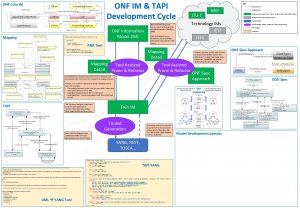
 Onf tapi
 Tapiols
 Advancements in solar energy
 Howonf
 Onf
Onf Onf profiles
 Bioflix membrane transport
 Active transport
 Primary active transport vs secondary active transport
 Now answer the following questions
 Bioflix activity membrane transport active transport
 Active transport vs passive transport venn diagram
 Active transport image
 Primary vs secondary active transport
 Unlike passive transport, active transport requires
 Tosca orchestration
 Conversation orchestration
 Broadband services bbs
 Hpe oo content packs
 Ibm resiliency orchestrator
 Orchestration designer
