
ONF Transport API Opening up Disaggregated Optical Transport





- Slides: 25
ONF Transport API Opening up Disaggregated Optical Transport Applications * Karthik Sethuraman, NEC Andrea Mazzini, Nokia Stephane St Laurent, Infinera Lyndon Ong, Ciena Dec 3, 2018 *animated slides
ONF TAPI Introduction & Overview 2
Transport API – Simple Problem Statement APP Open Standard T-API Network Orchestrator ONOS APIs ONOS ODL APIs ODL Proprietary APIs Proprietary
ONF Transport API (TAPI): Functional Architecture Application NE NE SDN NE Controller NE Transport API or Other NBIs Topology Service Connectivity Service OAM Service Path Computation Service Virtual Network Service Shared Network Information Context Transport API or Other SBIs Network NEElements SDN NE Controller NE Notification Service
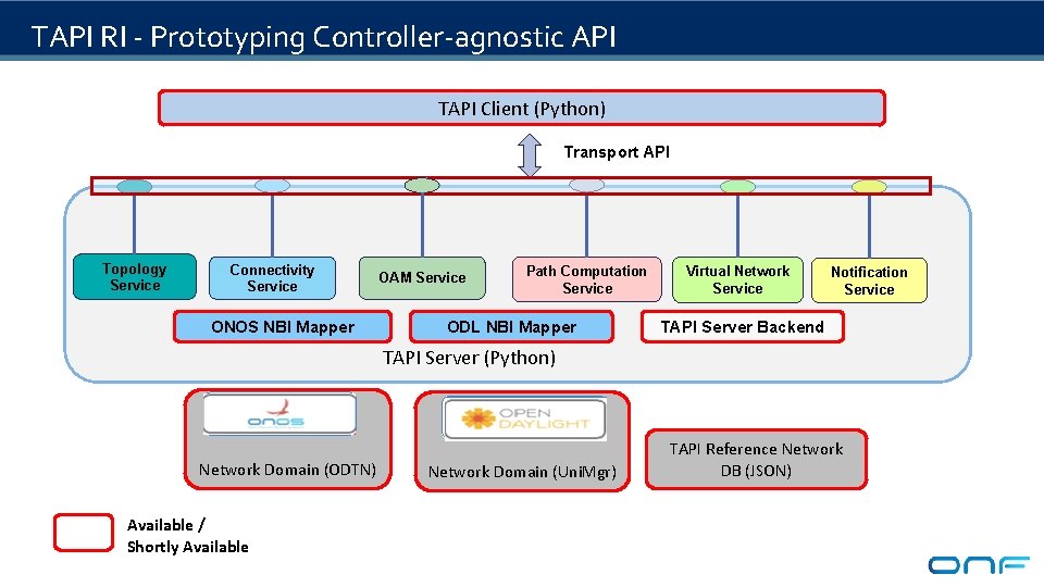
TAPI RI - Prototyping Controller-agnostic API TAPI Client (Python) Transport API Topology Service Connectivity Service ONOS NBI Mapper OAM Service Path Computation Service ODL NBI Mapper Virtual Network Service Notification Service TAPI Server Backend TAPI Server (Python) Network Domain (ODTN) Available / Shortly Available Network Domain (Uni. Mgr) TAPI Reference Network DB (JSON)
OIF Transport API Interop Demo (2014, 2016, 2018) Test Carriers OSS/App/Orchestrator TAPI Agent Multi-Domain Controller Common Abstraction model Transport API TAPI Agent Multi-Domain Controller Transport API Technology, Vendor Specific models TAPI Agent Domain Controller Test Vendors
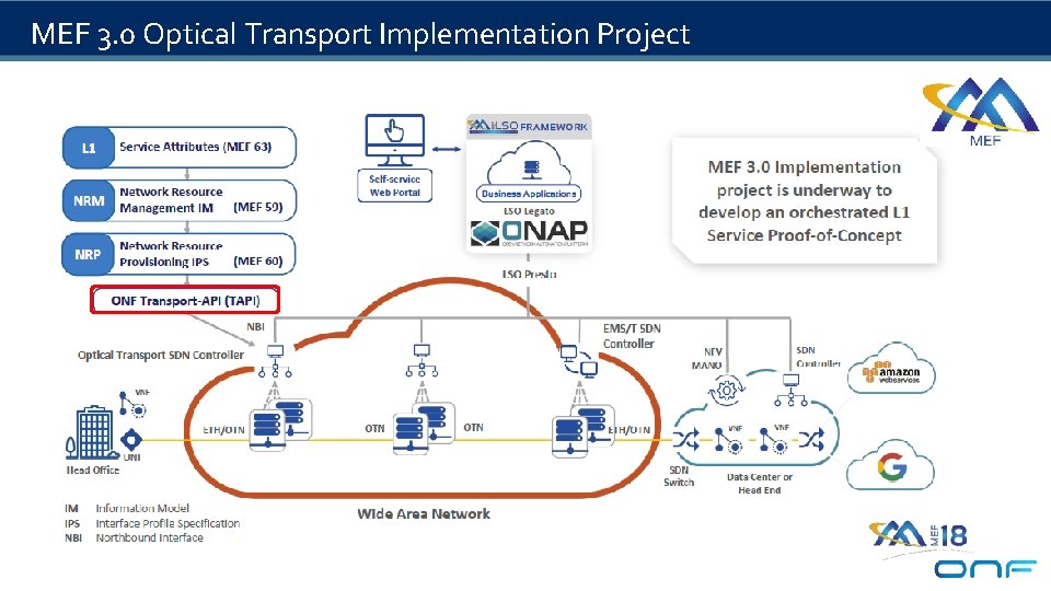
MEF 3. 0 Optical Transport Implementation Project
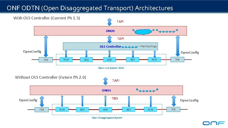
ONF ODTN (Open Disaggregated Transport) Architectures With OLS Controller (Current Ph 1. 5) TAPI ONOS TAPI OLS Controller Has topology Open. Config TRN MUX WSS AMP MUX TRN Open Line System (OLS) Without OLS Controller (Future Ph 2. 0) TAPI ONOS TBD Open. Config TRN MUX WSS AMP Open Disaggregated System Open. Config WSS MUX TRN
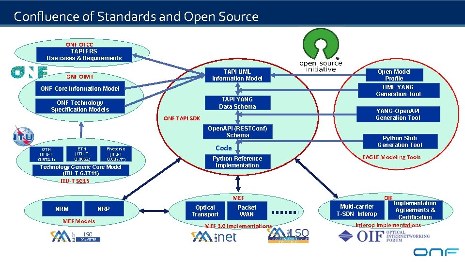
Confluence of Standards and Open Source ONF OTCC TAPI FRS Use cases & Requirements TAPI UML Information Model ONF OIMT ONF Core Information Model TAPI YANG Data Schema ONF Technology Specification Models ONF TAPI SDK Open Model Profile UML-YANG Generation Tool YANG-Open. API Generation Tool Open. API (RESTConf) Schema ETH (ITU-T G. 8052) OTN (ITU-T G. 874. 1) Photonic (ITU-T G. 807. 1*) Technology Generic Core Model (ITU-T G. 7711) Python Stub Generation Tool Code Python Reference Implementation EAGLE Modeling Tools ITU-T SG 15 OIF MEF NRM MEF Models NRP Optical Transport Packet WAN MEF 3. 0 Implementations Multi-carrier T-SDN Interop Implementation Agreements & Certification Interop Implementations
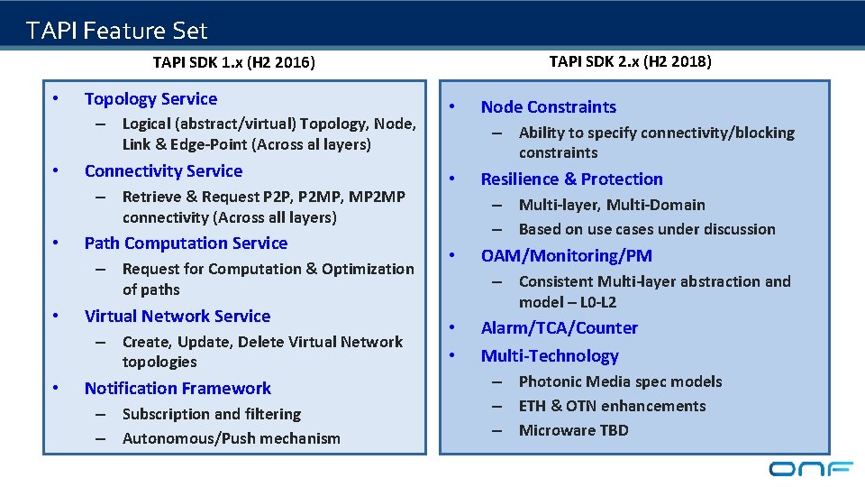
TAPI Feature Set TAPI SDK 2. x (H 2 2018) TAPI SDK 1. x (H 2 2016) • Topology Service – Logical (abstract/virtual) Topology, Node, Link & Edge-Point (Across al layers) • Connectivity Service – Retrieve & Request P 2 P, P 2 MP, MP 2 MP connectivity (Across all layers) • Path Computation Service – Request for Computation & Optimization of paths • Virtual Network Service – Create, Update, Delete Virtual Network topologies • Notification Framework – Subscription and filtering – Autonomous/Push mechanism • Node Constraints – Ability to specify connectivity/blocking constraints • Resilience & Protection – Multi-layer, Multi-Domain – Based on use cases under discussion • OAM/Monitoring/PM – Consistent Multi-layer abstraction and model – L 0 -L 2 • • Alarm/TCA/Counter Multi-Technology – Photonic Media spec models – ETH & OTN enhancements – Microware TBD
Transport API Summary TAPI Next Steps General Benefits • Provides functions necessary for multidomain orchestration – – • Different types of topology abstraction Supports multiple transport technologies – Packet Transport (Ethernet, MPLS-TP) – Optical Transport (OTN, DWDM) • Interoperability on North-South Orchestrator/Controller interface TAPI 2. x fixes & enhancements – Photonic Model updates based on ODTN feedback – ETH, L 1 & OAM alignment due to interaction with MEF (NRM-OAM/SOAM, L 1) projects – YANG & Open. API/RESTConf Best Practices – Based on MEF-PRESTO (ODL), ODTN (ONOS) and OIF (TAPI Interop) activity feedback Topology view and abstraction Connectivity establishment Hierarchical Abstraction Migration path for legacy systems – Abstract Node (single, edge, sliced, etc) – Abstract Link – Complete (1 -to-1) internal topology • • • TAPI 3. 0 Items (Current) – Equipment Inventory & configuration – Equipment, Holders (Rack/Shelf, etc), Connectors, Fiber, etc – Topology Pacs/Datatypes (Capacity, Cost, Latency, Risk parameters) enhancements – Rationalize/tune the component-system pattern for Topology & Connectivity
ONF TAPI Logical Topology & Forwarding Concepts with Photonic Example 12
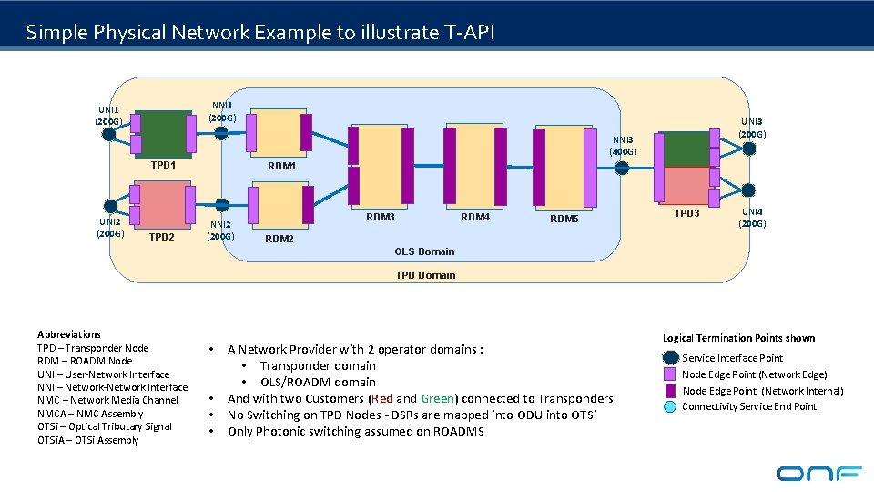
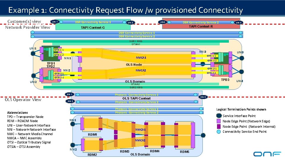
Simple Physical Network Example to illustrate T-API NNI 1 (200 G) UNI 3 (200 G) NNI 3 (400 G) TPD 1 UNI 2 (200 G) TPD 2 RDM 1 NNI 2 (200 G) TPD 3 RDM 4 RDM 3 RDM 5 TPD 3 UNI 4 (200 G) RDM 2 OLS Domain TPD Domain Abbreviations TPD – Transponder Node RDM – ROADM Node UNI – User-Network Interface NNI – Network-Network Interface NMC – Network Media Channel NMCA – NMC Assembly OTSi – Optical Tributary Signal OTSi. A – OTSi Assembly • • A Network Provider with 2 operator domains : • Transponder domain • OLS/ROADM domain And with two Customers (Red and Green) connected to Transponders No Switching on TPD Nodes - DSRs are mapped into ODU into OTSi Only Photonic switching assumed on ROADMS Logical Termination Points shown Service Interface Point Node Edge Point (Network Edge) Node Edge Point (Network Internal) Connectivity Service End Point
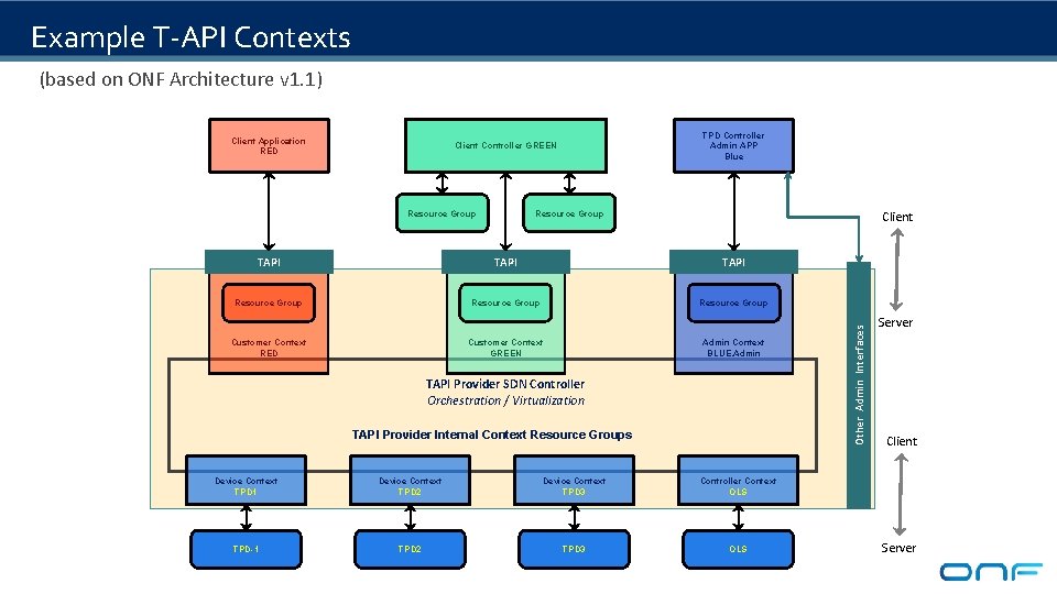
Example T-API Contexts (based on ONF Architecture v 1. 1) TPD Controller Admin APP Blue Client Controller GREEN Resource Group Client Resource Group TAPI Resource Group Customer Context RED Customer Context GREEN Admin Context BLUE. Admin TAPI Provider SDN Controller Orchestration / Virtualization TAPI Provider Internal Context Resource Groups Device Context TPD 1 Device Context TPD 2 Device Context TPD 3 Controller Context OLS TPD-1 TPD 2 TPD 3 OLS Other Admin Interfaces Client Application RED Server Client Server
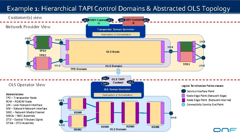
Example 1: Hierarchical TAPI Control Domains & Abstracted OLS Topology Customer(s) view UNI 1 Network Provider View TAPI Context UNI 3 -G UNI 2 TAPI Context -R UNI 4 Transponder Domain Controller Abstraction & Orchestration UNI 1 NNI 1 UNI 3 NNI 3 TPD 1 OLS Node TPD 3 TPD 2 UNI 2 NNI 2 TPD Domain NNI 1 OLS Operator View TPD 3 OLS Domain NNI 2 OLS TAPI Context NNI 3 Logical Termination Points shown OLS Domain Controller Abbreviations TPD – Transponder Node RDM – ROADM Node UNI – User-Network Interface NNI – Network-Network Interface NMC – Network Media Channel NMCA – NMC Assembly OTSi – Optical Tributary Signal OTSi. A – OTSi Assembly Service Interface Point Node Edge Point (Network Edge) Node Edge Point (Network Internal) Connectivity Service End Point Abstraction & Orchestration NNI 1 RDM 1 NNI 3 NNI 2 RDM 3 OLS Domain UNI 4 RDM 5
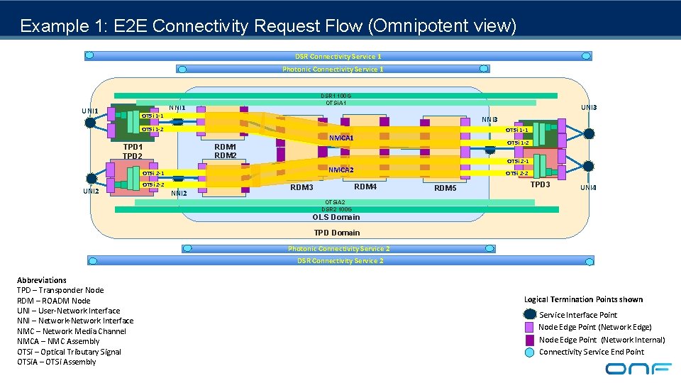
Example 1: E 2 E Connectivity Request Flow (Omnipotent view) DSR Connectivity Service 1 Photonic Connectivity Service 1 UNI 1 OTSi 1 -1 DSR 1 100 G OTSi. A 1 NNI 1 UNI 3 NNI 3 OTSi 1 -2 OTSi 1 -1 NMCA 1 TPD 2 OTSi 2 -1 NMCA 2 OTSi 2 -1 UNI 2 OTSi 1 -2 RDM 1 RDM 2 OTSi 2 -2 NNI 2 OTSi 2 -2 RDM 4 RDM 3 TPD 3 RDM 5 TPD 3 UNI 4 OTSi. A 2 DSR 2 100 G OLS Domain TPD Domain Photonic Connectivity Service 2 DSR Connectivity Service 2 Abbreviations TPD – Transponder Node RDM – ROADM Node UNI – User-Network Interface NNI – Network-Network Interface NMC – Network Media Channel NMCA – NMC Assembly OTSi – Optical Tributary Signal OTSi. A – OTSi Assembly Logical Termination Points shown Service Interface Point Node Edge Point (Network Edge) Node Edge Point (Network Internal) Connectivity Service End Point
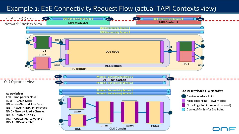
Example 1: E 2 E Connectivity Request Flow (actual TAPI Contexts view) Customer(s) view Network Provider View DSR Connectivity Service 1 UNI 2 UNI 3 TAPI Context-G DSR Connectivity Service 2 TAPI Context-R UNI 4 DSR Connectivity Service 1 Transponder Domain Controller DSR Connectivity Service 2 UNI 1 NNI 1 UNI 3 NNI 3 TPD 1 OLS Node TPD 3 TPD 2 UNI 2 NNI 2 TPD Domain Photonic Connectivity Service 1 OLS TAPI Context Photonic Connectivity Service 2 NNI 1 OLS Operator View Abbreviations TPD – Transponder Node RDM – ROADM Node UNI – User-Network Interface NNI – Network-Network Interface NMC – Network Media Channel NMCA – NMC Assembly OTSi – Optical Tributary Signal OTSi. A – OTSi Assembly TPD 3 OLS Domain NNI 2 NNI 3 Photonic Connectivity Service 1 Photonic Connectivity Service 2 Logical Termination Points shown Service Interface Point Node Edge Point (Network Edge) Node Edge Point (Network Internal) Connectivity Service End Point NNI 1 RDM 1 NNI 2 RDM 3 OLS Domain RDM 4 UNI 4 RDM 5
Example 1: Connectivity Request Flow /w provisioned Connectivity Resources Customer(s) view Network Provider View DSR Connectivity Service 1 UNI 2 UNI 3 TAPI Context-G DSR Connectivity Service 2 TAPI Context-R UNI 4 DSR Connectivity Service 1 DSR Connectivity Service 2 Transponder Domain Controller DSR 1 100 G OTSi. A 1 UNI 1 OTSi 1 -1 NNI 3 OTSi 1 -2 NMCA 1 NNI 1 TPD 2 OTSi 2 -1 NMCA 2 OTSi 2 -1 OTSi 2 -2 TPD 3 OTSi. A 2 DSR 2 100 G Photonic Connectivity Service 1 OLS TAPI Context Photonic Connectivity Service 2 NNI 1 NNI 2 Logical Termination Points shown Service Interface Point Node Edge Point (Network Edge) Node Edge Point (Network Internal) Connectivity Service End Point NNI 1 NMCA 1 RDM 1 NMCA 2 RDM 3 OLS Domain RDM 4 UNI 4 NNI 3 Photonic Connectivity Service 1 Photonic Connectivity Service 2 NNI 2 TPD 3 OTSi 2 -2 OLS Domain UNI 2 Abbreviations TPD – Transponder Node RDM – ROADM Node UNI – User-Network Interface NNI – Network-Network Interface NMC – Network Media Channel NMCA – NMC Assembly OTSi – Optical Tributary Signal OTSi. A – OTSi Assembly OTSi 1 -2 OLS Node NNI 2 OLS Operator View UNI 3 OTSi 1 -1 RDM 5
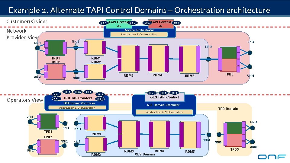
Example 2: Alternate TAPI Control Domains – Orchestration architecture Customer(s) view UNI 1 Network Provider View TAPI Context UNI 3 UNI 2 TAPI Context -G -R Service Orchestrator UNI 4 Abstraction & Orchestration NNI 1 UNI 3 NNI 3 TPD 1 TPD 2 RDM 1 RDM 2 UNI 2 RDM 3 NNI 2 NNI 1 UNI 1 Operators View UNI 2 NNI 2 TPD 3 NNI 1 UNI 3 TPD TAPI Context TPD Domain Controller RDM 4 NNI 2 TPD 3 RDM 5 UNI 4 NNI 3 OLS TAPI Context UNI 4 OLS Domain Controller Abstraction & Orchestration TPD Domain Abstraction & Orchestration UNI 1 UNI 3 TPD 1 NNI 1 RDM 1 TPD 2 NNI 3 NNI 2 UNI 2 RDM 3 OLS Domain RDM 4 RDM 5 TPD 3 NNI 3 TPD 3 UNI 4
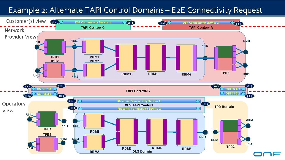
Example 2: Alternate TAPI Control Domains – E 2 E Connectivity Request Customer(s) view Flow DSR Connectivity Service 1 UNI 4 TAPI Context-R UNI 3 NNI 3 TPD 1 TPD 2 RDM 1 RDM 2 UNI 2 Operators View DSR Connectivity Service 2 NNI 1 UNI 2 TAPI Context-G Network Provider View UNI 1 UNI 3 RDM 3 NNI 2 DSR CS 1 -1 DSR CS 2 -1 TPD 3 RDM 4 TPD 3 RDM 5 NNI 1 NNI 3 TAPI Context-G NNI 2 Photonic Connectivity Service 1 OLS TAPI Context Photonic Connectivity Service 2 NNI 1 NNI 2 NNI 3 DSR CS 1 -2 DSR CS 2 -2 UNI 4 UNI 3 UNI 4 TPD Domain UNI 1 UNI 3 TPD 1 NNI 1 RDM 1 TPD 2 NNI 3 NNI 2 UNI 2 RDM 3 OLS Domain RDM 4 RDM 5 TPD 3 NNI 3 TPD 3 UNI 4
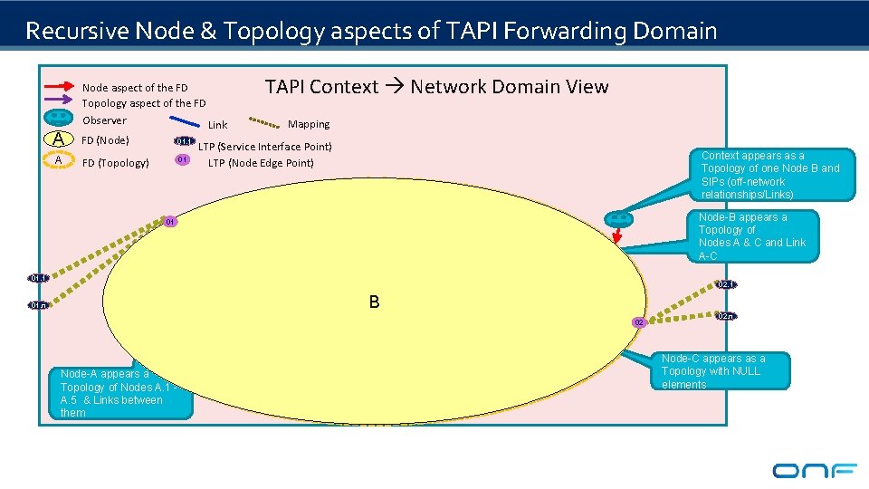
Recursive Node & Topology aspects of TAPI Forwarding Domain TAPI Context Network Domain View Node aspect of the FD Topology aspect of the FD Observer Link A FD (Node) 01. 1 A FD (Topology) 01 01 Mapping LTP (Service Interface Point) LTP (Node Edge Point) A. 1 13 11 12 A A. 3 14 01. n 16 Node-A appears a Topology of Nodes A. 1 A. 5 & Links between them B A 17 01. 1 A. 2 Context appears as a Topology of one Node B and SIPs (off-network relationships/Links) 15 19 A. 4 Node-B appears a Topology of Nodes A & C and Link A-C 05 02. 1 18 B 20 A. 5 04 03 C 02 02. n Node-C appears as a Topology with NULL elements
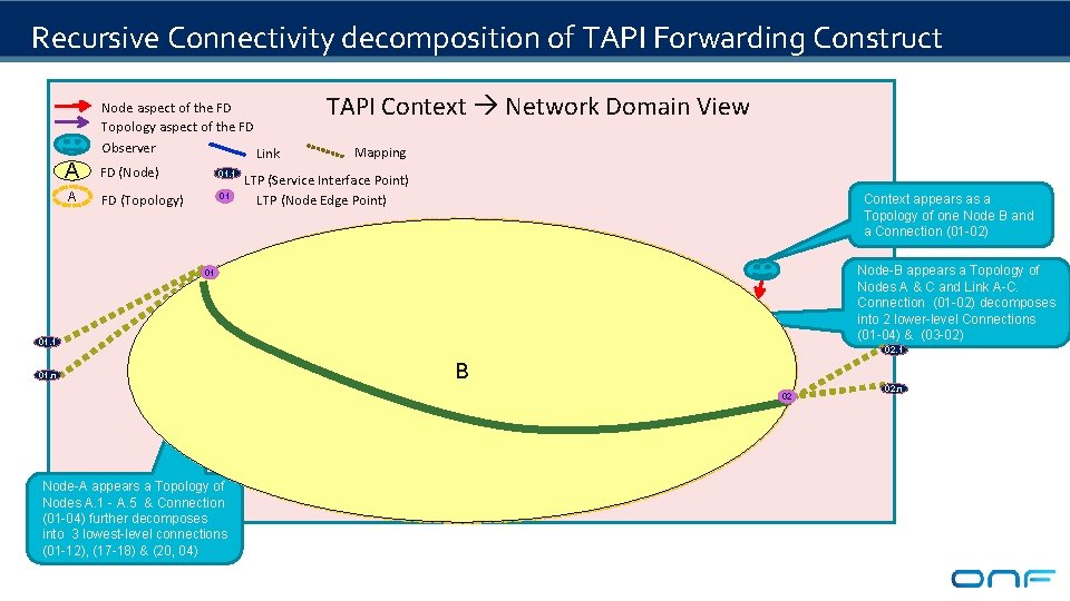
Recursive Connectivity decomposition of TAPI Forwarding Construct TAPI Context Network Domain View Node aspect of the FD Topology aspect of the FD Observer Link A FD (Node) 01. 1 A FD (Topology) 01 01 Mapping LTP (Service Interface Point) LTP (Node Edge Point) A. 1 13 11 12 A A. 3 14 01. n Node-A appears a Topology of Nodes A. 1 - A. 5 & Connection (01 -04) further decomposes into 3 lowest-level connections (01 -12), (17 -18) & (20, 04) B A 17 01. 1 16 A. 2 Context appears as a Topology of one Node B and a Connection (01 -02) 15 19 A. 4 Node-B appears a Topology of Nodes A & C and Link A-C. Connection (01 -02) decomposes into 2 lower-level Connections (01 -04) & (03 -02) 05 02. 1 18 B 20 A. 5 04 03 C 02 02. n
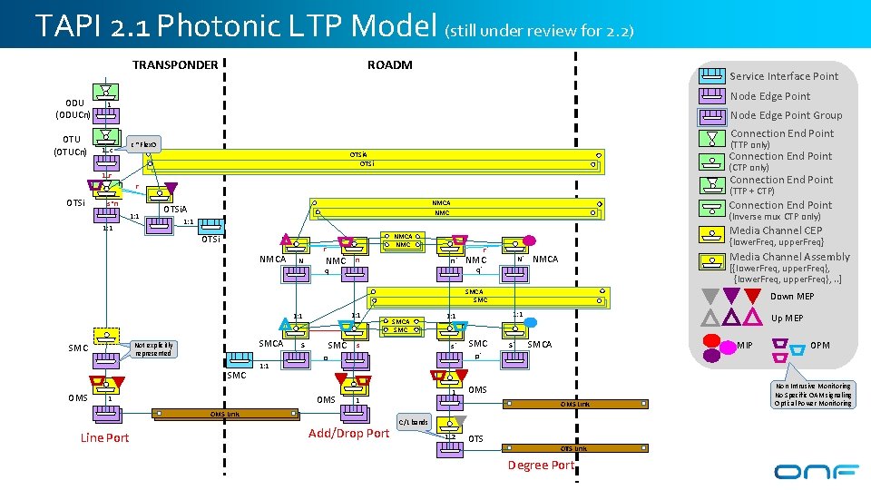
TAPI 2. 1 Photonic LTP Model (still under review for 2. 2) TRANSPONDER ODU (ODUCn) OTU (OTUCn) ROADM Service Interface Point Node Edge Point 1 Node Edge Point Group Connection End Point (TTP only) c ~Flex. O 1. . c Connection End Point OTSi. A OTSi (CTP only) 1. . r Connection End Point r OTSi s*n 1: 1 (TTP + CTP) OTSi. A 1: 1 Connection End Point NMCA NMC (Inverse mux CTP only) 1: 1 OTSi NMCA r N Media Channel CEP NMCA NMC n {lower. Freq, upper. Freq} r` n` NMC N` Media Channel Assembly NMCA [{lower. Freq, upper. Freq}, . . ] q` q SMCA SMC 1: 1 SMCA Not explicitly modeled represented SMC OMS 1: 1 SMC S s s` SMC S` Up MEP SMCA MIP OPM p` 1 1 OMS Link Line Port 1: 1 p OMS 1 SMCA SMC Down MEP Add/Drop Port OMS Link C/L bands 1. . 2 OTS Link Degree Port Non Intrusive Monitoring No Specific OAM signaling Optical Power Monitoring
References Thank you 24
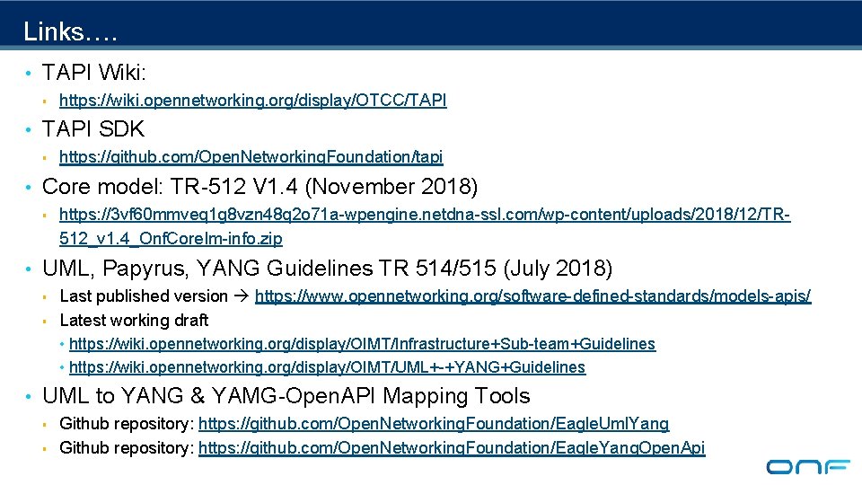
Links…. • TAPI Wiki: § https: //wiki. opennetworking. org/display/OTCC/TAPI • TAPI SDK § https: //github. com/Open. Networking. Foundation/tapi • Core model: TR-512 V 1. 4 (November 2018) § https: //3 vf 60 mmveq 1 g 8 vzn 48 q 2 o 71 a-wpengine. netdna-ssl. com/wp-content/uploads/2018/12/TR 512_v 1. 4_Onf. Core. Im-info. zip • UML, Papyrus, YANG Guidelines TR 514/515 (July 2018) § § Last published version https: //www. opennetworking. org/software-defined-standards/models-apis/ Latest working draft • https: //wiki. opennetworking. org/display/OIMT/Infrastructure+Sub-team+Guidelines • https: //wiki. opennetworking. org/display/OIMT/UML+-+YANG+Guidelines • UML to YANG & YAMG-Open. API Mapping Tools § § Github repository: https: //github. com/Open. Networking. Foundation/Eagle. Uml. Yang Github repository: https: //github. com/Open. Networking. Foundation/Eagle. Yang. Open. Api