Sweep Overview Mark Ortel Sales Support Eng Conditioning


- Slides: 147

Sweep Overview Mark Ortel Sales Support Eng

Conditioning the Network for Triple Play Services § Know Your HFC Network § System Sweep and Ingress Suppression § Testing and Hardening the Drop (Home Wiring) § Line Conditioning to Optimize Two-way Plant Performance § Fiber Optic Testing Maintenance 2 © 2005 JDSU. All rights reserved. JDSU CONFIDENTIAL & PROPRIETARY INFORMATION

Bandwidth Demand is Growing Exponentially All Video on Demand Unicast per Subscriber Megabits per Second 100 90 High Definition Video on Demand 80 Video Blogs 70 Podcasting 60 Video on Demand 50 Video Mail 40 Online Gaming 30 Digital Photos 20 Vo. IP 10 E-mail Digital Music Web Browsing Time 3 © 2005 JDSU. All rights reserved. JDSU CONFIDENTIAL & PROPRIETARY INFORMATION

5 © 2005 JDSU. All rights reserved. JDSU CONFIDENTIAL & PROPRIETARY INFORMATION

Voice Quality Impairments – it’s not always the plant! Telco Problem? Cable Provider Problem? Customer Problem? Cable Provider Problem? Where is the Problem? What is the Problem? MEDIA POP PSTN Media. GWTrunk Media Slot-Port? Gateway DSP Card. Port-CPU? Router-Slot. Port? LSP/VLAN, Route? What’s Core IPthe Network problem? Trunk Media Gateway High utilization lead to congestion causing jitter, MEDIA GW POP dropped packets and DSP codec increased transit delay, performance, echo mis-configured routing canceller config. , jitter can cause inappropriate buffer config. / packet hops leading to increased drops latency © 2005 JDSU. All rights reserved. Cable CMTS UPSTREAM or DOWNSTREAM? What’s the problem? CORE IP NTWK 6 CMTS-Blade. Port or Switch -Slot-Port? What’s the problem? PSTN Aggregation switch CMTS MEDIA POP analog problems on PSTN path passed through to IP network HUB SITE CABLE PLANT Cable Modem MTA POTS Phone HOME Background noise, handset RF downstream and/or speaker/mic interference, HUB SITE upstream errors leading to inadequate volume, inside Excessive NE polling IP packet loss, bandwidth wiring, mis-configured MTA and/or high utilization capacity limitations (esp. (Co. S-Diffserv / firewall lead to congestion upstream) may lead to settings), wireless phone causing jitter, dropped CMTS congestion (dropped delay exacerbates echo packets and increased IP packets) and excessive problems, MTA DSP/echo transit delay jitter (packet drops by codec) canceller performance JDSU CONFIDENTIAL & PROPRIETARY INFORMATION

‘Pre-HFC’ Networks § § No Optics Standardized ‘Tree & Branch’ Architecture Few Amplifier Types Limited Operating Levels Networks were optimized forward plant performance with minimal reverse plant engineering. 7 © 2005 JDSU. All rights reserved. JDSU CONFIDENTIAL & PROPRIETARY INFORMATION

‘Pre-HFC’ Networks § § No Optics Standardized ‘Tree & Branch’ Architecture Few Amplifier Types Limited Operating Levels Headend Networks were optimized forward plant performance with minimal reverse plant engineering. 8 © 2005 JDSU. All rights reserved. JDSU CONFIDENTIAL & PROPRIETARY INFORMATION

HFC Networks § Combines fiber optics with coaxial distribution network § Return path is more sensitive than the forward path § Most of the ingress comes from home wiring on low value taps § Wide variety of hardware with many connectors Today’s ‘HFC” networks must be optimized for both forward and reverse performance 9 © 2005 JDSU. All rights reserved. JDSU CONFIDENTIAL & PROPRIETARY INFORMATION

HFC Network Architecture NODE 10 © 2005 JDSU. All rights reserved. JDSU CONFIDENTIAL & PROPRIETARY INFORMATION

HFC Network Architecture NODE 11 © 2005 JDSU. All rights reserved. JDSU CONFIDENTIAL & PROPRIETARY INFORMATION

Basic DOCSIS® Network CMTS Downstream Laser and Upstream Optical Receivers Fiber Nodes Cable Modems Downstream 0 Upstream 0 Cable Modems Upstream 1 Cable Modems Upstream 2 Cable Modems Upstream 3 Coax 12 © 2005 JDSU. All rights reserved. Fiber JDSU CONFIDENTIAL & PROPRIETARY INFORMATION Coax

Types of Lasers used in HFC Networks § Fabry-Pérot (FP) – Less Expensive – Mediocre Performance – No Isolation or Cooling Required § Distributed Feedback (DFB) – Expensive – High Performance – Isolation and Cooling Required 13 © 2005 JDSU. All rights reserved. JDSU CONFIDENTIAL & PROPRIETARY INFORMATION

Forward System § Diverging System § Constant Outputs with Variable Inputs § Fixed Signals – video / audio / digital carriers § System Noise – is the sum of cascaded amplifiers § Balance or Align (Sweep) – compensate for losses before the amp 14 © 2005 JDSU. All rights reserved. JDSU CONFIDENTIAL & PROPRIETARY INFORMATION

Forward Path Unity Gain OUT +36 d. Bm. V IN +12 d. Bm. V IN +11 d. Bm. V OUT +36 d. Bm. V 2 d. B 24 d. B @ 750 MHz AMP # 2 18 d. B @ 750 MHz AMP # 1 8 d. B 23 d. B @ 750 MHz AMP # 3 IN +10 d. Bm. V AMP # 4 OUT +36 d. Bm. V 15 © 2005 JDSU. All rights reserved. JDSU CONFIDENTIAL & PROPRIETARY INFORMATION

Reverse System § Converging System § Constant Inputs with Variable Outputs § No Fixed Signals – impulse digital carriers § System Noise – is the sum of all active components § Balance or Align (Sweep) – compensate for losses after the amp 16 © 2005 JDSU. All rights reserved. JDSU CONFIDENTIAL & PROPRIETARY INFORMATION

Return Path Unity Gain IN +20 d. Bm. V OUT +24 d. Bm. V OUT +26 d. Bm. V IN +20 d. Bm. V 2 d. B 4 d. B @ 40 MHz AMP # 2 2 d. B @ 40 MHz AMP # 1 8 d. B 4 d. B @ 40 MHz AMP # 3 OUT +30 d. Bm. V AMP # 4 IN +20 d. Bm. V 17 © 2005 JDSU. All rights reserved. JDSU CONFIDENTIAL & PROPRIETARY INFORMATION

Reverse Path Impairments § Ingress and electrical noise § Common Path Distortion (CPD) § Thermal (intrinsic) noise § Laser clipping noise § Micro-Reflections 18 © 2005 JDSU. All rights reserved. JDSU CONFIDENTIAL & PROPRIETARY INFORMATION

Reverse Path Impairments There a variety of impairments that can affect two-way operation. They are classified in three main categories: stationary impairments, which include thermal noise, intermodulation distortion, and frequency response problems; transient impairments, which include RF ingress, impulse noise, and signal clipping; and multiplicative impairments, which include transient hum modulation and intermittent connections. 19 © 2005 JDSU. All rights reserved. JDSU CONFIDENTIAL & PROPRIETARY INFORMATION

Reverse Path Impairments Thermal noise —The majority of thermal noise is generated in active components. Besides choosing active equipment with a relatively low noise figure, there is little else that you can do about thermal noise in active devices, other than ensure proper network alignment. 20 © 2005 JDSU. All rights reserved. JDSU CONFIDENTIAL & PROPRIETARY INFORMATION

Reverse Path Impairments Intermodulation distortion—The most common types of intermodulation distortion affecting the reverse path are second and third order distortions. These can be generated in amplifiers and reverse lasers. A more troubling type of intermodulation can occur in some passive components. It is known as common path distortion (CPD), and usually occurs at a dissimilar metals interface where a thin oxide layer has formed. 21 © 2005 JDSU. All rights reserved. JDSU CONFIDENTIAL & PROPRIETARY INFORMATION

Reverse Path Impairments Frequency response— Frequency response problems are due to improper network alignment, unterminated lines, or damaged components. When reverse frequency response and equipment alignment have been done incorrectly or not at all, the result can be excessive thermal noise, distortions, and group delay errors. 22 © 2005 JDSU. All rights reserved. JDSU CONFIDENTIAL & PROPRIETARY INFORMATION

Reverse Path Impairments RF ingress — The 5 -40 MHz reverse spectrum is shared with numerous over-the-air users. Signals in the over-the-air environment include high power shortwave broadcasts, amateur radio, citizens band, government, and other two-way radio communications. 23 © 2005 JDSU. All rights reserved. JDSU CONFIDENTIAL & PROPRIETARY INFORMATION

Downstream and Upstream Noise Additions Headend Reverse System “Noise Funneling” Headend Ingress from seven amplifiers ends up at the headend. Forward Signals Noise 24 © 2005 JDSU. All rights reserved. JDSU CONFIDENTIAL & PROPRIETARY INFORMATION

Reverse Path Impairments Impulse noise —Most reverse data transmission errors have been found to be caused by bursts of impulse noise. Impulse noise is characterized by its fast risetime and short duration. Common sources include vehicle ignitions, neon signs, static from lightning, power line switching transients, electric motors, electronic switches, and household appliances. 25 © 2005 JDSU. All rights reserved. JDSU CONFIDENTIAL & PROPRIETARY INFORMATION

Impulse Noise in the Upstream 26 © 2005 JDSU. All rights reserved. JDSU CONFIDENTIAL & PROPRIETARY INFORMATION

Sample: “Loose Plant” Performance History • Average noise floor at 17 MHz varies consistently by time of day • Indication of return path with an ingress problem. • Maintenance now will prevent future problems 11: 00 PM 7: 00 AM Single Frequency Time Window for 72 Hours from one return path 27 © 2005 JDSU. All rights reserved. JDSU CONFIDENTIAL & PROPRIETARY INFORMATION

Sample: ‘Tight’ Performance History • 17 MHz noise floor tracked over time • Average noise floor stays fairly flat and consistent over the 3 day period Inconsistent Problem (high peak, low average) Peak Average Minimum Single Frequency Time Window for 72 Hours from one return path 28 © 2005 JDSU. All rights reserved. JDSU CONFIDENTIAL & PROPRIETARY INFORMATION

Sample: “Telephony” Performance History • Average telephony signal at 36 MHz varies consistently by time of day • Indication of higher telephony usage times 11: 00 PM 7: 00 AM Single Frequency Time Window for 3 days from one return path 29 © 2005 JDSU. All rights reserved. JDSU CONFIDENTIAL & PROPRIETARY INFORMATION

6 MHz CPD 30 © 2005 JDSU. All rights reserved. JDSU CONFIDENTIAL & PROPRIETARY INFORMATION

Reverse Path Impairments Signal clipping —RF ingress and impulse noise can cause signal clipping, or compression, in reverse plant active components. Excessive levels from in-home devices such as pay-per-view converters also can cause clipping. Clipping occurs in reverse amplifiers and optical equipment. 31 © 2005 JDSU. All rights reserved. JDSU CONFIDENTIAL & PROPRIETARY INFORMATION

Ingress § 75 – 90% of ingress originates in the subscriber’s home § To minimize the effects of ingress, operate the subscriber terminals (modems & set-tops) near maximum transmit level 32 © 2005 JDSU. All rights reserved. JDSU CONFIDENTIAL & PROPRIETARY INFORMATION

Common Path Distortion (A. K. A. CPD) § Non-linear mixing from a diode junction – Corrosion (metal oxide build-up) in the coaxial portion of the HFC network – Dissimilar metal contacts – 4 main groups of metals • • Magnesium and its alloys Cadmium, Zinc, Aluminum and its alloys Iron, Lead, Tin, & alloys (except stainless steel) Copper, Chromium, Nickel, Silver, Gold, Platinum, Titanium, Cobalt, Stainless Steel, and Graphite § Second and third order distortions 33 © 2005 JDSU. All rights reserved. JDSU CONFIDENTIAL & PROPRIETARY INFORMATION

Common Path Distortion (A. K. A. CPD) CPD distortions are spaced at 6 MHz apart from each other starting at 6 MHz 24 MHz 34 © 2005 JDSU. All rights reserved. JDSU CONFIDENTIAL & PROPRIETARY INFORMATION

24 Hour Performance History Max Hold Detail Graph DOCSIS® Modem Carrier Wide band noise beyond 42 MHz diplex roll-off Diplex rolloff above 42 MHz 35 © 2005 JDSU. All rights reserved. JDSU CONFIDENTIAL & PROPRIETARY INFORMATION

Thermal Noise and Laser Noise § Maintain a tight control of reverse RF signal levels – Laser drive level too high • causes excessive laser clipping – Laser drive level too low • reduces C/N and C/I ratios Reverse levels must be held to a relatively narrow ‘window’ in order to guarantee that they fall comfortably between a lower limit (imposed by the noise floor) and a higher limit (set by laser clipping noise) 36 © 2005 JDSU. All rights reserved. JDSU CONFIDENTIAL & PROPRIETARY INFORMATION

Micro-reflections Causes: § § § Damaged or missing end-of-line terminators Damaged or missing chassis terminators on directional coupler, splitter, or multiple-output amplifier unused ports Loose center conductor seizure screws Unused tap ports not terminated; this is especially critical on low value taps, but all unused tap ports should be terminated with 75 -ohm terminations (locking terminators without resistors or stingers do not terminate the tap port) Poor isolation in splitters, taps and directional couplers Unused customer premises splitter and directional coupler ports not terminated Use of so-called self-terminating taps at feeder ends-of-line; these are the equivalent of splitters, and do not terminate the feeder cable unless all tap ports are terminated Kinked or damaged cable (includes cracked cable, which causes a reflection and ingress) Defective or damaged actives or passives (water-damaged, water-filled, cold solder joint, corrosion, loose circuit board screws, etc. ) Cable-ready TVs and VCRs connected directly to the drop (return loss on most cable-ready devices is poor) Some traps and filters have been found to have poor return loss in the upstream, especially those used for data-only service RON HRANAC rhranacj@cisco. com 37 © 2005 JDSU. All rights reserved. JDSU CONFIDENTIAL & PROPRIETARY INFORMATION

Why Go Digital? § Efficiency – Source signals are digital • Standard and High Definition TV (SDTV, HDTV) – High Speed Data and Digital Video is more efficient than analog • Transmit equivalent of 6 to 10 analog channels (VCR quality) or 2 HDTV programs over one 6 MHz bandwidth § Quality – Better Picture and Sound Quality – Less Susceptible to noise • Error detection and correction is possible § Flexibility – Data-casting easily multiplexed into digital signal – Higher Data Security 38 © 2005 JDSU. All rights reserved. JDSU CONFIDENTIAL & PROPRIETARY INFORMATION

What is Digital? § Source and Destination is digital data – Assign unique patterns of 1’s and 0’s § Transmission path is via an analog QAM carrier – Choice of modulation is the one that optimizes bandwidth (data versus frequency ‘space’) and resiliency to noise 00 01 10 11 00 Generate Digital © 2005 JDSU. All rights reserved. 10 Receive Digital QAM Analog Carrier 39 01 JDSU CONFIDENTIAL & PROPRIETARY INFORMATION 11

Quadrature Amplitude Modulation (QAM) § QAM combines QPSK and AM modulation. § QAM uses 2 channels of information each carrying half the data. AM Modulator Bit Stream 10 11 I Channel Carrier Combiner Carrier + 90° AM Modulator Q Channel 40 © 2005 JDSU. All rights reserved. JDSU CONFIDENTIAL & PROPRIETARY INFORMATION

Vector Sum of I and Q Channels § Combining 2 carriers 90° of out of phase results in a carrier with amplitude and phase modulation 4 Levels of Q 00 4 Levels of I Channel 10 + 11. . 11 4 Levels of I Data Stream. . 10 01 = 00 01 4 Levels of Q Channel 11 41 © 2005 JDSU. All rights reserved. . . 10 11. . 10 16 QAM JDSU CONFIDENTIAL & PROPRIETARY INFORMATION

Constellations, Symbols and Digital Bits § Each “dot” on constellation represents a unique symbol § Each unique symbol represents unique digital bits § Digital data is parsed into data lengths that encode the symbol waveform 4 Levels of I Channel 4 Levels of Q Channel 16 QAM 42 © 2005 JDSU. All rights reserved. JDSU CONFIDENTIAL & PROPRIETARY INFORMATION

64 QAM and 256 QAM § 64 QAM has 8 levels of I and 8 levels of Q making 64 possible locations for the carrier § 256 QAM has 16 levels of I and 16 levels of Q making 256 possible locations for the carrier 8 Levels of I Channel 16 Levels of Q Channel 8 Levels of Q Channel 64 QAM 43 © 2005 JDSU. All rights reserved. 256 QAM JDSU CONFIDENTIAL & PROPRIETARY INFORMATION

QAM and CATV § 16 QAM is part of the DOCSIS® 1. 0/1. 1 upstream specifications § 64 QAM and 256 QAM is used for both digital video and DOCSIS downstream, allowing more digital data transmission using the same 6 MHz bandwidth – Transmit equivalent of 10 to 12 analog channels (standard definition) or 2 HDTV programs over one 6 MHz bandwidth § Standard for data over Cable – Cable systems provide higher signal to noise ratios than over-the-air transmission. A well designed and maintained cable plant meets these QAM signal to noise requirements 44 © 2005 JDSU. All rights reserved. JDSU CONFIDENTIAL & PROPRIETARY INFORMATION

QAM Data Capacity (Annex B) 45 16 QAM 64 QAM 256 QAM (Upstream) (Downstream) Symbol Rate (Msps) 2. 560 5. 0569 5. 3605 (@ 6 MHz) Bits per symbol 4 6 8 Channel Data Rate (Mbps) 10. 24 30. 3417 42. 8843 Information bit rate(Mbps) 9. 0 26. 9704 38. 8107 Overhead 12. 11% 11. 11% 9. 5% © 2005 JDSU. All rights reserved. (@ 3. 20 MHz) JDSU CONFIDENTIAL & PROPRIETARY INFORMATION

Constellation Display The constellation is a visual representation of the I and Q plots 46 © 2005 JDSU. All rights reserved. JDSU CONFIDENTIAL & PROPRIETARY INFORMATION

Effects of Noise and Interference moves the carrier away from its ideal location causing a spreading of the cluster of dots. Ideal Locations 47 © 2005 JDSU. All rights reserved. JDSU CONFIDENTIAL & PROPRIETARY INFORMATION

Modulation Error Ratio (MER) § Analogous to S/N or C/N § A measure of how tightly symbols are recorded with respect to desired symbol location § MER(d. B) = 20 x log RMS error magnitude average symbol magnitude § Good MER – 64 QAM: 28 d. B MER Average symbol – 256 QAM: 32 d. B MER magnitude RMS error magnitude 48 © 2005 JDSU. All rights reserved. JDSU CONFIDENTIAL & PROPRIETARY INFORMATION

Constellation Zoom § Zooming in on the constellation you can see how the carrier spread and how close it came to the decision boundaries. Decision Boundaries 50 © 2005 JDSU. All rights reserved. JDSU CONFIDENTIAL & PROPRIETARY INFORMATION

The Carrier, by the way, is ANALOG Modulation Analog Content – Analog Carrier Digital Content – Analog Carrier 51 © 2005 JDSU. All rights reserved. JDSU CONFIDENTIAL & PROPRIETARY INFORMATION

Path. Trak QAM Analyzer View – Good Node MER & Level Avg/Max/Min QPSK & 16 QAM Constellation Live MER, Level & Symbol Count MER & Level Graphed over Time 52 © 2005 JDSU. All rights reserved. JDSU CONFIDENTIAL & PROPRIETARY INFORMATION

Path. Trak QAM Analyzer View – Bad Node Interference easily visible in 16 QAM constellation Interference causing intermittent low MER 53 © 2005 JDSU. All rights reserved. JDSU CONFIDENTIAL & PROPRIETARY INFORMATION

“Back to the Basics” Troubleshooting § Majority of problems are basic physical layer issues § Check AC power § Most of the test strategy remains the same – divide and conquer technique § Check forward and return RF levels, analog and digital § Check forward / reverse ingress § Do a visual inspection of connectors / passives § Replace questionable connectors / passives § Tighten F-connectors per your company’s installation policy – Be very careful not to over tighten connectors on CPE (TVs, VCRs, converters etc. ) and crack or damage input RFI integrity 54 © 2005 JDSU. All rights reserved. JDSU CONFIDENTIAL & PROPRIETARY INFORMATION

System Sweep and Ingress Suppression Why sweep? Why suppress Ingress?

WHY SWEEP? • Less manpower needed • Sweeping can reduce the number of service calls Cracked hardline found with SWEEP Channel 12 video problems Internet not working VOD not working 56 © 2005 JDSU. All rights reserved. JDSU CONFIDENTIAL & PROPRIETARY INFORMATION

What faults cause CATV signals to fail ? (80 -90% of the time, the same faults…) §Success rate of finding and fixing the following problems using: – – – 57 5% Spectrum Analyzers Signal Levels 7% Visual TV-picture inspection TILT 11% BER Digital Analyzers Gain / Loss 23% Signal Level Meters 21% Reverse Ingress Suck-outs (notches) C/N 72% Forward & Reverse Sweep HUM CTB/CSO Intermodulation CPD - Forward and Reverse Source: Research 11/97 -2/98 Market survey with 200 US and European CATV op Reverse Ingress BER / MER Reflections / Standing waves © 2005 JDSU. All rights reserved. JDSU CONFIDENTIAL & PROPRIETARY INFORMATION

WHY SWEEP? § CATV amplifiers have a trade-off between noise and distortion performance § Tightly controlling frequency response provides the best compromise between noise and distortion. 58 © 2005 JDSU. All rights reserved. JDSU CONFIDENTIAL & PROPRIETARY INFORMATION

Segmented Error Budgets 59 © 2005 JDSU. All rights reserved. JDSU CONFIDENTIAL & PROPRIETARY INFORMATION

Sweep Verifies Construction Quality • Sweep can find craftsmanship or component problems that aren’t revealed with other tests • Damaged cable • Poor connectorization • Amplifier RF response throughout its frequency range • Gain • Slope • Loose seizure screws, module hardware……. 60 © 2005 JDSU. All rights reserved. JDSU CONFIDENTIAL & PROPRIETARY INFORMATION

Frequency Response Definition § System’s ability properly to transmit signals from headend to subscriber throughout the designed frequency range § “Sweep” tests verify performance to design specifications § Expected Results: N/2 + X = max flatness variation • where n = number of amplifiers in cascade • where x = best case flatness figure § Typical Flattness formulas are: § n/10+1 old systems with 30 amp cascade 400 MHz Bandwidth § N/2+2 new systems with and 5 to 7 amp cascade 750 MHz Bandwidth 61 © 2005 JDSU. All rights reserved. JDSU CONFIDENTIAL & PROPRIETARY INFORMATION

Test Probes § Will always be bi-directional unless they are in series with the circuit § Higher loss probes provide less of an impedance mismatch, but lower levels § F-to-Housing adapters cause severe standing waves because of; – Bad grounding – RF power splitting – Impedance mismatch § Be careful with in-line pads while probing seizure screws – Not usually dc blocked 62 © 2005 JDSU. All rights reserved. JDSU CONFIDENTIAL & PROPRIETARY INFORMATION

Sweep Response of a Splitter INPUT RF OUTPUT 63 © 2005 JDSU. All rights reserved. JDSU CONFIDENTIAL & PROPRIETARY INFORMATION RF IN

100 ft of RG-59 cable INPUT RF OUT RF IN OUTPUT 64 © 2005 JDSU. All rights reserved. JDSU CONFIDENTIAL & PROPRIETARY INFORMATION

Sweep Response of 17 d. B Tap Port Tap RF Out 65 © 2005 JDSU. All rights reserved. JDSU CONFIDENTIAL & PROPRIETARY INFORMATION

Sweep Response of a Amplifier Forward RF out RF in 20 d. B Amplifier Return 12 d. B RF out 66 © 2005 JDSU. All rights reserved. JDSU CONFIDENTIAL & PROPRIETARY INFORMATION RF in

A Sweep Finds Problems That Signal Level Measurements Misalignment Standing Waves Roll off at band edges 67 © 2005 JDSU. All rights reserved. JDSU CONFIDENTIAL & PROPRIETARY INFORMATION

Balancing Amplifiers Balancing amplifiers using tilt Headend Node Reference Signal Lose Face Plate, or crack cable shield Sweep response with a Resonant Frequency Absorption 68 © 2005 JDSU. All rights reserved. JDSU CONFIDENTIAL & PROPRIETARY INFORMATION No Termination Sweep response with standing waves

Step 1) Forward & Reverse Sweep WHY SWEEP? Headend Lose Face Plate, or crack cable shield No Termination D = 492*Vp/F F Node Reference Signal Sweep response with a Resonant Frequency Absorption 69 © 2005 JDSU. All rights reserved. JDSU CONFIDENTIAL & PROPRIETARY INFORMATION Sweep response with standing waves

Types of Sweep § Sweepless Sweep § Forward Sweep § Return Sweep 70 © 2005 JDSU. All rights reserved. JDSU CONFIDENTIAL & PROPRIETARY INFORMATION

“Sweepless” Sweep Method § Developed by Wavetek in the late 1980 s § Compares headend levels to system test point levels § Totally non-interfering (no sweep injection signal) § Relatively inexpensive (no headend unit) § Normal level variations in headed signals cause loss of valid reference information § Blank spectrum not tested 71 © 2005 JDSU. All rights reserved. JDSU CONFIDENTIAL & PROPRIETARY INFORMATION

‘Sweepless’ Sweep 72 © 2005 JDSU. All rights reserved. JDSU CONFIDENTIAL & PROPRIETARY INFORMATION

Sweepless Sweep with Channel drop out 73 © 2005 JDSU. All rights reserved. JDSU CONFIDENTIAL & PROPRIETARY INFORMATION

Sweep with Transmitter § Sweep transmitter and headend monitor § Constantly monitors video, audio, and digital carriers plus sweep insertion points § Transmits any level variations to the SDA-5500 or DSAM 6000 on a telemetry carrier to update the reference – Keeps receiver up to date on headend levels 74 © 2005 JDSU. All rights reserved. JDSU CONFIDENTIAL & PROPRIETARY INFORMATION

Typical Forward Sweep Response Fiber Node 75 © 2005 JDSU. All rights reserved. Line Extender JDSU CONFIDENTIAL & PROPRIETARY INFORMATION End of Line Tap

Bench Sweep Amplifiers Verify old modules 76 © 2005 JDSU. All rights reserved. JDSU CONFIDENTIAL & PROPRIETARY INFORMATION

Beware of Taps Port 1 thru 8 not terminated 77 © 2005 JDSU. All rights reserved. Port 1 thru 8 terminated JDSU CONFIDENTIAL & PROPRIETARY INFORMATION

System Problems Resonant Frequency absorption Low end roll off High end roll off 55. 25 MHz 78 © 2005 JDSU. All rights reserved. 745. 25 MHz JDSU CONFIDENTIAL & PROPRIETARY INFORMATION

System Problem vs. Signature 100 MHz / 3 d. B / Signature System Problem 79 © 2005 JDSU. All rights reserved. JDSU CONFIDENTIAL & PROPRIETARY INFORMATION

Headend to Tap Typical system not swept or balanced for 6 months Ampifiers not balanced System Sweep Transmitter 3 SR Cracked Hardline Stealth Sweep FILE AUTO 1 abc 4 jkl 7 stu 2 5 def ghi 3 mno 6 vwx 9 help FREQ pqr status CHAN yz ENTER alpha SETUP 8 x. space 0 +/- CLEAR PRINT LEVEL TILT SCAN SWEEP C/N HUM MOD SPECT H light FCN L SDA-5500 - Headend unit FCC Proof Failure Customer Complaints Noisy pictures! HD Tiling 80 © 2005 JDSU. All rights reserved. JDSU CONFIDENTIAL & PROPRIETARY INFORMATION

Headend to Tap Typical system after Sweep and Balance Ampifiers balanced System Sweep Transmitter 3 SR Hardline good Condition Stealth Sweep FILE AUTO 1 abc 4 jkl 7 stu 2 5 def ghi 3 mno 6 vwx 9 help FREQ pqr status CHAN yz ENTER alpha SETUP 8 x. space 0 +/- CLEAR PRINT LEVEL TILT SCAN SWEEP C/N HUM MOD SPECT H light FCN L SDA-5500 - Headend unit FCC Proof PASS! Customers Satisfied! 81 © 2005 JDSU. All rights reserved. JDSU CONFIDENTIAL & PROPRIETARY INFORMATION

Analog Integrity is Still Paramount, Supplemented by Digital Measurements § Majority of “digital” issues involve basic analog maintenance of the RF plant – – – 83 Levels, including network tilt, must be optimized RF distortions such as CSO and CTB can affect QAM carriers Managing hum has been shown to improve QAM carrier quality Carrier-to-noise and signal-to-noise (MER on QAM channels) BER and DQI for intermittent impairments Ingress management © 2005 JDSU. All rights reserved. JDSU CONFIDENTIAL & PROPRIETARY INFORMATION

Goal § The objective in reverse path alignment is to maintain unity gain with constant inputs and minimize noise and ingress. § Set all optical receivers in the headend to same output level and ideally the same noise floor to optimize C/N ratio. – The reverse path noise is the summation of all noise from all the amplifiers in the reverse path. 84 © 2005 JDSU. All rights reserved. JDSU CONFIDENTIAL & PROPRIETARY INFORMATION

Sweep Reference Considerations § Typically the node is used for the reference § Use test probe designed for node/amp § It’s a good engineering practice to store a new reference each day § Establish reference points to simplify ongoing maintenance (sweep file overlay) § Need to know amps hidden losses in return path (Block diagrams / Schematics) § Need to know where to inject sweep pulses and the recommended injection levels 85 © 2005 JDSU. All rights reserved. JDSU CONFIDENTIAL & PROPRIETARY INFORMATION

Optimizing the Node Headend System Sweep Transmitter 3 SR Stealth Sweep FILE AUTO 1 abc 4 jkl 7 stu 2 5 def ghi 3 mno 6 vwx 9 Forward Laser Activation and maintenance of optical nodes by DSAM 6000 with Reverse Sweep help FREQ pqr status CHAN yz ENTER alpha SETUP 8 x. space 0 +/- CLEAR H light FCN PRINT LEVEL TILT SCAN SWEEP C/N HUM MOD SPECT L SDA-5500 - Headend unit Reverse-path optical receivers 86 © 2005 JDSU. All rights reserved. JDSU CONFIDENTIAL & PROPRIETARY INFORMATION Activation and maintenance of the trunk network by SDA-5000 + SDA-OPT 1 or SDA-4040 D

Return Path “X” LEVEL Reverse Combiner X d. Bm. V NODE Optical Receiver X d. Bm. V NODE Pad input of the SDA-5510 for 0 d. Bm. V System Sweep Transmitter 3 SR Stealth Sweep FILE 1 abc 2 def 3 ghi help FREQ AUTO 4 jkl 5 mno 6 pqr status CHAN SETUP 7 stu 8 vwx 9 yz x CLEAR . space 0 +/- PRINT 87 LEVEL C/N TILT SCAN SWEEP HUM MOD SPECT © 2005 JDSU. All rights reserved. alpha ENTER light FCN All Return Path RF signal levels must be set to same output “X” level at the optical receiver in the headend or hubsite with the same “X” level input at the node. JDSU CONFIDENTIAL & PROPRIETARY INFORMATION

Return Path “X” LEVEL X d. Bm. V Reverse Combiner X d. Bm. V NODE Optical Receiver NODE X d. Bm. V NODE Pad input of the SDA-5510 for 0 d. Bm. V System Sweep Transmitter 3 SR Stealth Sweep FILE 1 abc 2 def 3 ghi help FREQ AUTO 4 jkl 5 mno 6 pqr status CHAN SETUP 7 stu 8 vwx 9 yz x CLEAR . space 0 +/- PRINT 88 LEVEL C/N TILT SCAN SWEEP HUM MOD SPECT © 2005 JDSU. All rights reserved. alpha ENTER light FCN All Return Path RF signal levels must be set to same output “X” level at the optical receiver in the headend or hubsite with the same “X” level input at the node. JDSU CONFIDENTIAL & PROPRIETARY INFORMATION

Return Path “X” LEVEL X d. Bm. V Reverse Combiner X d. Bm. V NODE Optical Receiver NODE X d. Bm. V NODE Pad input of the SDA-5510 for 0 d. Bm. V System Sweep Transmitter 3 SR Stealth Sweep FILE 1 abc 2 def 3 ghi help FREQ AUTO 4 jkl 5 mno 6 pqr status CHAN SETUP 7 stu 8 vwx 9 yz x CLEAR . space 0 +/- PRINT 89 LEVEL C/N TILT SCAN SWEEP HUM MOD SPECT © 2005 JDSU. All rights reserved. alpha ENTER light FCN All Return Path RF signal levels must be set to same output “X” level at the optical receiver in the headend or hubsite with the same “X” level input at the node. JDSU CONFIDENTIAL & PROPRIETARY INFORMATION

Return Path “X” LEVEL X d. Bm. V Reverse Combiner X d. Bm. V NODE Optical Receiver NODE X d. Bm. V Pad input of the SDA-5510 for 0 d. Bm. V System Sweep Transmitter 3 SR Stealth Sweep FILE 1 abc 2 def 3 ghi help FREQ AUTO 4 jkl 5 mno 6 pqr status CHAN SETUP 7 stu 8 vwx 9 yz x CLEAR . space 0 +/- PRINT 90 LEVEL C/N TILT SCAN SWEEP HUM MOD SPECT © 2005 JDSU. All rights reserved. alpha ENTER light FCN All Return Path RF signal levels must be set to same output “X” level at the optical receiver in the headend or hubsite with the same “X” level input at the node. JDSU CONFIDENTIAL & PROPRIETARY INFORMATION

Reverse Noise Floor X - 40 d. B Reverse Combiner X - 40 d. B NODE Optical Receiver NODE 1 abc 2 def 3 ghi help FREQ AUTO 4 jkl 5 mno 6 pqr status CHAN SETUP 7 stu 8 vwx 9 yz x CLEAR . 91 C/N TILT SCAN SWEEP HUM MOD SPECT Desired noise floors into node Stealth Sweep FILE space 0 +/- PRINT LEVEL X - 40 d. B Return Telemetry must have at least a 20 d. B SNR System Sweep Transmitter 3 SR X - 40 d. B NODE X - 40 d. B © 2005 JDSU. All rights reserved. alpha ENTER light FCN All Return noise floor levels should be maintained to supply approximately “X level minus 40 d. B” going into the node. JDSU CONFIDENTIAL & PROPRIETARY INFORMATION

ALIGNING THE RETURN PATH § Choose operating levels that maximize the distortion performance of your return path § Get all the information that you can on your nodes and amps from your manufacturer § Create a sweep procedure for your system – make up a chart showing injection levels at each test point 92 © 2005 JDSU. All rights reserved. JDSU CONFIDENTIAL & PROPRIETARY INFORMATION

ALIGNING THE RETURN PATH 93 © 2005 JDSU. All rights reserved. JDSU CONFIDENTIAL & PROPRIETARY INFORMATION

Test Point Compensation § Graphical user interface § Store & recall of test point setups 94 © 2005 JDSU. All rights reserved. JDSU CONFIDENTIAL & PROPRIETARY INFORMATION

Test Point Compensation § Graphical user interface § Store & recall of test point setups 95 © 2005 JDSU. All rights reserved. JDSU CONFIDENTIAL & PROPRIETARY INFORMATION

User Interface: Forward Sweep Raw Forward Sweep Reference the Sweep Trace Save the Reference name Referenced Sweep Trace Save the File for Records Choose & Save the File name Troubleshoot or Move to next device in the line 96 © 2005 JDSU. All rights reserved. JDSU CONFIDENTIAL & PROPRIETARY INFORMATION

User Interface: Reverse Sweep Raw Reverse Sweep Reference the Sweep Trace Save the Reference name Referenced Reverse Sweep Save the File for Records Choose & Save the File name Troubleshoot or Move to next device in the line 97 © 2005 JDSU. All rights reserved. JDSU CONFIDENTIAL & PROPRIETARY INFORMATION

User Interface: Test Point Compensation Test Point Comp menu can be accessed two ways: • Settings Hotkey in Sweep Measurement • Shift+4 on the keypad at any time List of current TPC Files Create a new TPC file Name and save the TP device Edit new TPC file Specify TP device loses Pick Reverse Tel & Insertion levels Forward summary specs Reverse Summary Specs TPC now active on all tests 98 © 2005 JDSU. All rights reserved. JDSU CONFIDENTIAL & PROPRIETARY INFORMATION

User Interface: Markers and Zooming Move Markers to desired locations Go to Zoom Go to View Menu New Frequency Range 99 © 2005 JDSU. All rights reserved. JDSU CONFIDENTIAL & PROPRIETARY INFORMATION

User Interface: Sweep Settings Turning on Tilt Compensation activates the Tilt settings Select Settings Tab Sweep Settings For bidirectional test points set the Reverse Sweep Port to Port 1 For directional test points set it to Port 2 and attach the reverse test point to port 2 and the forward test point to port 1 100 © 2005 JDSU. All rights reserved. JDSU CONFIDENTIAL & PROPRIETARY INFORMATION

User Interface: Telemetry Settings Set the telemetry of the SDA-5500 headend unit and SDA-5510 (if available) Select Settings Tab Path. Trak’s Field View Telemetry Frequency If using an SDA-5500 headend unit only set the reverse Sweep to Single User If also using a SDA-5510 select Multi User for reverse Sweep 101 © 2005 JDSU. All rights reserved. JDSU CONFIDENTIAL & PROPRIETARY INFORMATION

Sweeping Out The sweep and alignment procedure for both the forward and return path starts at the node and then moves toward the end of line NODE X d. Bm. V Telemetry = X d. Bm. V Connect to Input Test Point on Node 102 © 2005 JDSU. All rights reserved. JDSU CONFIDENTIAL & PROPRIETARY INFORMATION

Sweeping Out Maintain unity gain with constant input Set TP Loss as required NODE X d. Bm. V Telemetry = X d. Bm. V Connect to Input of First Reverse Amp 103 © 2005 JDSU. All rights reserved. JDSU CONFIDENTIAL & PROPRIETARY INFORMATION

Sweeping Out Maintain unity gain with constant input Set TP Loss as required NODE X d. Bm. V Telemetry = X d. Bm. V Connect to Input of First Reverse Amp 104 © 2005 JDSU. All rights reserved. JDSU CONFIDENTIAL & PROPRIETARY INFORMATION

Sweeping Out Maintain unity gain with constant input Set TP Loss as required NODE X d. Bm. V Telemetry = X d. Bm. V Connect to Input of First Reverse Amp 105 © 2005 JDSU. All rights reserved. JDSU CONFIDENTIAL & PROPRIETARY INFORMATION

Sweeping Out Maintain unity gain with constant input Set TP Loss as required NODE X d. Bm. V Telemetry = X d. Bm. V Connect to Input of First Reverse Amp 106 © 2005 JDSU. All rights reserved. JDSU CONFIDENTIAL & PROPRIETARY INFORMATION

Sweeping Out Maintain unity gain with constant input Set TP Loss as required NODE X d. Bm. V Telemetry = X d. Bm. V Connect to Input of First Reverse Amp 107 © 2005 JDSU. All rights reserved. JDSU CONFIDENTIAL & PROPRIETARY INFORMATION X d. Bm. V

Common problems typically identified in outside plant § Damaged or missing end-of-line terminators § Damaged or missing chassis terminators on directional coupler, splitter or multiple-output amplifier unused ports § Loose center conductor seizure screws § Unused tap ports not terminated. This is especially critical on lower value taps § Unused drop passive ports not terminated § Use of so-called self-terminating taps (4 d. B two port; 8 d. B four port and 10/11 d. B eight port) at feeder ends-of-line. Such taps are splitters, and do not terminate the line unless all F ports are properly terminated 108 © 2005 JDSU. All rights reserved. JDSU CONFIDENTIAL & PROPRIETARY INFORMATION

Common problems typically identified in outside plant § Kinked or damaged cable (including cracked cable, which causes a reflection and ingress). § Defective or damaged actives or passives (water-damaged, waterfilled, cold solder joint, corrosion, loose circuit-board screws, etc. ). § Cable-ready TVs and VCRs connected directly to the drop. (Return loss on most cable-ready devices is poor. ) § Some traps and filters have been found to have poor return loss in the upstream, especially those used for data-only service. 109 © 2005 JDSU. All rights reserved. JDSU CONFIDENTIAL & PROPRIETARY INFORMATION

Intermittent Connections § Poor craftsmanship on connectors § Loose center seizure screws & fiber connectors § Radial cracks in hard-line coaxial cable § Cold solder joints § Bad accessories 110 © 2005 JDSU. All rights reserved. JDSU CONFIDENTIAL & PROPRIETARY INFORMATION

The Situation § Can’t justify taking the system down to troubleshoot § Unacceptable to the subscribers who will; – Lose communication – Get a slower throughput – Have periodic “clicking” in their telephone calls § To be non-intrusive we must; – Understand test points – Apply new procedures and applications – Learn new troubleshooting techniques 111 © 2005 JDSU. All rights reserved. JDSU CONFIDENTIAL & PROPRIETARY INFORMATION

Typical Problem Areas § Taps – Most ingress comes from houses with tap values of 17 d. B or less § House Wiring – Drop Cable & F Connectors are approximately ~95% of Problem § Amplifiers, hard line cable and the rest of the system are a small percentage of the problem if a proper leakage maintenance program is performed. 112 © 2005 JDSU. All rights reserved. JDSU CONFIDENTIAL & PROPRIETARY INFORMATION

Taps § Taps are a combination of a DC and a splitter network § Taps give an actual representation of what the subscriber is seeing and transmitting in to 8 Port 23 d. B tap § Points to remember; – Lower valued taps equal more through loss 113 © 2005 JDSU. All rights reserved. JDSU CONFIDENTIAL & PROPRIETARY INFORMATION This would be a DC-12 The splitter network = ~11 d. B of loss

Testing at the Seizure Screws § If the problem is at the Forward Output, continue on § If the problem is at the Forward Input and not the Forward Output, then the problem is from one of the drops § Spring loaded seizure screw probes create a good ground and quick connect without causing outages Input Output Forward Path Return Path 114 © 2005 JDSU. All rights reserved. JDSU CONFIDENTIAL & PROPRIETARY INFORMATION

Testing at the Seizure Screws § Use a 20 db pad with AC block when using spring loaded seizure screw probes Input Output Forward Path Return Path 115 © 2005 JDSU. All rights reserved. JDSU CONFIDENTIAL & PROPRIETARY INFORMATION

Taps are made up of a Directional Coupler and Splitters Probe the seizure screw for ingress 4 Port Tap Disconnect one drop at a time to determine the point of entry 116 © 2005 JDSU. All rights reserved. JDSU CONFIDENTIAL & PROPRIETARY INFORMATION

Taps - Probe the Seizure Screws for Ingress & CPD If the problem is at the FWD Output of tap, continue on towards end of line If the problem is at the FWD Input and not the FWD Output, then the problem is likely from one of the drops Forward Path Return Path Disconnect one drop at a time to determine the point of entry 117 © 2005 JDSU. All rights reserved. JDSU CONFIDENTIAL & PROPRIETARY INFORMATION

Electrical Impulse Noise from One House • Reverse Spectrum shot at customer's drop 118 © 2005 JDSU. All rights reserved. JDSU CONFIDENTIAL & PROPRIETARY INFORMATION

Path. Trak™ Field View Option Path. Trak Field View option combined with JDSU meters provides a complete “Find & Fix” field troubleshooting solution • • • 119 Path. Trak Field View option on SDA and DSAM platform enables techs to greatly reduce MTTR (Mean Time to Repair), which increases customer satisfaction and loyalty Path. Trak Field View option for DSAM provides a programmable CW carrier to aid in troubleshooting return problems Both SDA and DSAM have low pass filter for troubleshooting bi-directional test points © 2005 JDSU. All rights reserved. JDSU CONFIDENTIAL & PROPRIETARY INFORMATION

Tracking Down Ingress and CPD NODE 120 © 2005 JDSU. All rights reserved. JDSU CONFIDENTIAL & PROPRIETARY INFORMATION

Live Spectrum Analysis – RBW Settings 121 © 2005 JDSU. All rights reserved. JDSU CONFIDENTIAL & PROPRIETARY INFORMATION

Live Spectrum Analysis – RBW Setting +19. 61 d. Bm. V 300 k. Hz RBW (Resolution Bandwidth setting) 122 © 2005 JDSU. All rights reserved. JDSU CONFIDENTIAL & PROPRIETARY INFORMATION

Live Spectrum Analysis – RBW Setting +25. 95 d. Bm. V 1, 000 k. Hz RBW (Resolution Bandwidth setting) 123 © 2005 JDSU. All rights reserved. JDSU CONFIDENTIAL & PROPRIETARY INFORMATION

Live Spectrum Analysis – RBW Setting +11. 31 d. Bm. V 30 k. Hz RBW (Resolution Bandwidth setting) 124 © 2005 JDSU. All rights reserved. JDSU CONFIDENTIAL & PROPRIETARY INFORMATION

Quick and Easy Spectrum Scan § View from 4 to 110 MHz spectrum with programmable pass/fail limits § Spectrum view with adjustable marker and zoom function § Selectable peak hold § Store in work folder § Standard feature on DSAM Platform 125 © 2005 JDSU. All rights reserved. JDSU CONFIDENTIAL & PROPRIETARY INFORMATION

FM Band Ingress 126 © 2005 JDSU. All rights reserved. JDSU CONFIDENTIAL & PROPRIETARY INFORMATION

Testing the RF Network 7 d. B TAP Return Equalizer Drop Cable Disconnect drop from tap and check for ingress House coming from customer’s home wiring OLDER TV SET WIRELESS LAPTOP DIGITAL SET-TOP If ingress is detected, terminate other end of drop and scan spectrum again for ingress GROUND BLOCK COMPUTOR 2 -Way Amplifier High Pass Filter Vo. IP ETHERNET 3 -Way Splitter e. MTA-CABLE MODEM INGRESS SPECTRUM MEASUREMENTS 127 © 2005 JDSU. All rights reserved. JDSU CONFIDENTIAL & PROPRIETARY INFORMATION ONLINE GAMING

Troubleshooting is “Back to the Basics” § § § § Majority of problems are basic physical layer issues Most of the tests remain the same Check power Check forward levels, analog and digital Check forward / reverse ingress Do a visual check of connectors / passives Replace questionable connectors / passives Tighten F-connectors per your company’s installation policy – Be very careful not to over tighten connectors on CPE (TVs, VCRs, converters etc. ) and crack or damage input RFI integrity 128 © 2005 JDSU. All rights reserved. JDSU CONFIDENTIAL & PROPRIETARY INFORMATION

Line Conditioning and Return Path Equalization Why should you worry about return attenuation?

Level Control Scheme 130 © 2005 JDSU. All rights reserved. JDSU CONFIDENTIAL & PROPRIETARY INFORMATION

Optimizing (Conditioning) the Reverse Path § Adding reverse path attenuation – – – 131 enables flexible, more cost efficient design increases C/N performance of communicating devices reduces dynamic range of communication devices reduces opportunities for reverse laser clipping affords a ‘more forgiving’ network set-up during reverse balance and alignment © 2005 JDSU. All rights reserved. JDSU CONFIDENTIAL & PROPRIETARY INFORMATION

Step Attenuators Low value taps produce the majority of ingress and trouble calls within a typical HFC network. This is due to the lack of sufficient reverse attenuation found in higher-value taps. Applied directly to the tap port, Step Attenuators provide unity gain with all cable modems and other critical reverse transmission products like digital voice and high-speed Internet. -1. 3 d. B 5 MHz 54 MHz -12 d. B 40 MHz 132 © 2005 JDSU. All rights reserved. JDSU CONFIDENTIAL & PROPRIETARY INFORMATION

Reverse ‘Window’ § Problem: Reverse window can exceed dynamic range of terminals Required reverse input level: 22 d. Bm. V 23 20 45. 0 Forward levels: 45/35 d. Bm. V 17 11 In red: required tap port reverse level Terminal reverse 'window': 55 - 41 = 14 d. B NID -10 d. B 55 d. Bm. V -3 d. B © 2005 JDSU. All rights reserved. NID 41 d. Bm. V Terminal 133 8 JDSU CONFIDENTIAL & PROPRIETARY INFORMATION Terminal 38. 0

Reduced Reverse ‘Window’ § Same area, ‘NID’ design standardized – reverse terminal ‘window’ improved by 7 d. B Required reverse input level: 22 d. Bm. V 23 20 45. 0 17 11 In red: required tap port reverse level Terminal reverse 'window' 55 - 48 = 7 d. B Forward levels: 45/35 d. Bm. V NID -10 d. B 55 d. Bm. V -10 d. B © 2005 JDSU. All rights reserved. NID 48 d. Bm. V Terminal 134 8 JDSU CONFIDENTIAL & PROPRIETARY INFORMATION Terminal 38. 0

Reverse Tap Port ‘Window’ - High Forward Levels, LEQ w/o RC Required Reverse Level @ Amplifier Input Port: 15 d. Bm. V DC-12 29 Forward levels: 51/41 d. Bm. V 132' 110' 26 17 44. 0 44. 9 110' 43. 2 132' In red: required tap port reverse level 23 120' 41. 0 14 43. 3 120' 20 39. 1 110' 11 110' 35. 2 8 39. 4 § Reverse ‘Window’ of required tap port levels: 44. 9 - 31. 2 = 13. 7 d. B 135 © 2005 JDSU. All rights reserved. JDSU CONFIDENTIAL & PROPRIETARY INFORMATION 8 31. 2

Reverse Tap Port ‘Window’ - High Forward Levels, Using LEQ/RC Required Reverse Level @ Amplifier Input Port: 15 d. Bm. V DC-12 29 Forward levels: 51/41 d. Bm. V 132' 110' 26 110' 23 120' 20 17 44. 0 43. 2 44. 9 132' In blue: previous reverse level required 41. 0 14 43. 3 120' 39. 1 8 110' 11 44. 2 35. 2 110' 8 40. 2 31. 2 9 d. B reverse pad installed 39. 4 § Reverse ‘Window’ narrowed from 13. 7 to: 44. 9 39. 1 = 5. 8 d. B 136 © 2005 JDSU. All rights reserved. JDSU CONFIDENTIAL & PROPRIETARY INFORMATION

Reverse Tap Port ‘Window’ - Low Density, LEQ w/o RC Required reverse level: 15 d. Bm. V 29 1, 560' 4 Forward levels: 51/41 d. Bm. V 44. 0 25. 5 § Reverse ‘Window”range of required tap port levels: 44. 0 - 25. 5 = 18. 5 d. B 137 © 2005 JDSU. All rights reserved. JDSU CONFIDENTIAL & PROPRIETARY INFORMATION

Reverse Tap Port ‘Window’ - Low Density, Using LEQ/RC Required reverse level: 15 d. Bm. V 29 1, 560' 4 15 d. B reverse pad installed Forward levels: 51/41 d. Bm. V 44. 0 In blue: previous reverse level required 40. 5 25. 5 § Reverse ‘Window’ narrowed from 18. 5 to: 44. 0 40. 5 = 4. 5 d. B 138 © 2005 JDSU. All rights reserved. JDSU CONFIDENTIAL & PROPRIETARY INFORMATION

Noise Floor Levels § Be careful with spectrum analyzer level readings § The level is based off the RBW setting and will be very different from one setting to another § A -20 d. Bm. V noise floor with 30 k. Hz RBW is really 1. 2 d. Bm. V in a 4 MHz bandwidth § That’s why measurements with no point of reference are worthless § At least if there’s a reference carrier present, you can make a relative measurement 139 © 2005 JDSU. All rights reserved. JDSU CONFIDENTIAL & PROPRIETARY INFORMATION

Severe Transient Hum Modulation § The RF choke can saturate with too much current draw and cause the ferrite material to break down § Same thing can happen in customer installed passives § Notice that this looks a lot like CPD 140 © 2005 JDSU. All rights reserved. JDSU CONFIDENTIAL & PROPRIETARY INFORMATION

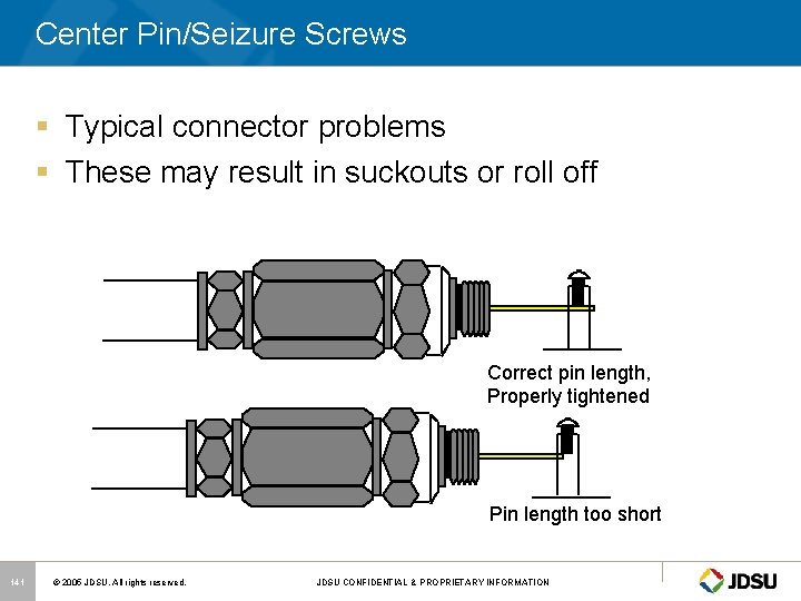
Center Pin/Seizure Screws § Typical connector problems § These may result in suckouts or roll off Correct pin length, Properly tightened Pin length too short 141 © 2005 JDSU. All rights reserved. JDSU CONFIDENTIAL & PROPRIETARY INFORMATION

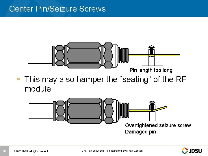
Center Pin/Seizure Screws Pin length too long § This may also hamper the “seating” of the RF module Overtightened seizure screw Damaged pin 142 © 2005 JDSU. All rights reserved. JDSU CONFIDENTIAL & PROPRIETARY INFORMATION

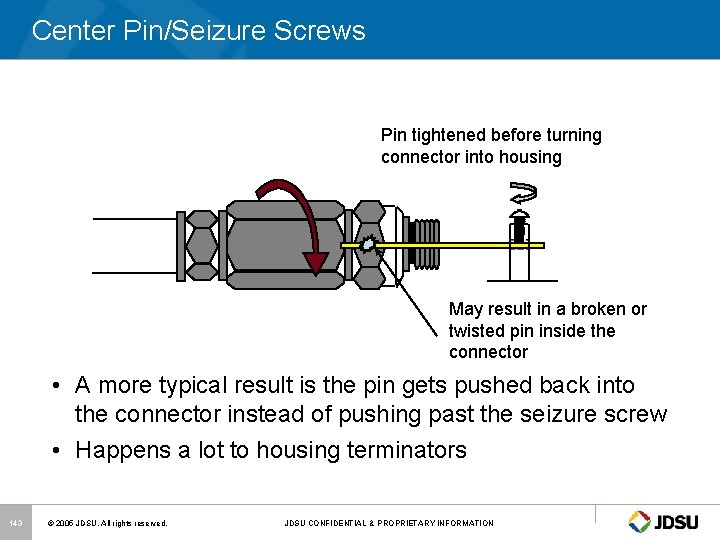
Center Pin/Seizure Screws Pin tightened before turning connector into housing May result in a broken or twisted pin inside the connector • A more typical result is the pin gets pushed back into the connector instead of pushing past the seizure screw • Happens a lot to housing terminators 143 © 2005 JDSU. All rights reserved. JDSU CONFIDENTIAL & PROPRIETARY INFORMATION

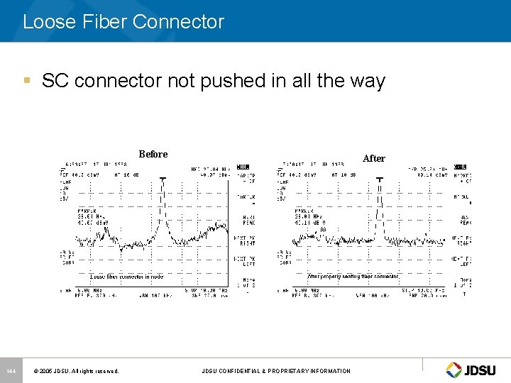
Loose Fiber Connector § SC connector not pushed in all the way Before 144 © 2005 JDSU. All rights reserved. After JDSU CONFIDENTIAL & PROPRIETARY INFORMATION

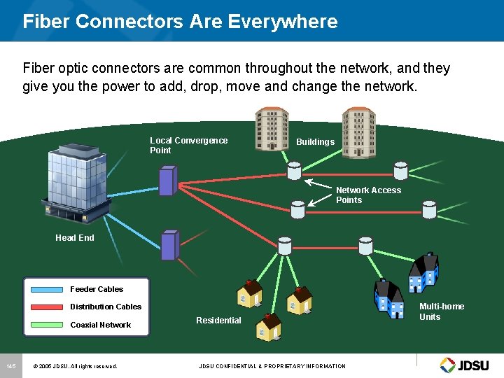
Fiber Connectors Are Everywhere Fiber optic connectors are common throughout the network, and they give you the power to add, drop, move and change the network. Local Convergence Point Buildings Network Access Points Head End Feeder Cables Distribution Cables Coaxial Network 145 © 2005 JDSU. All rights reserved. Residential JDSU CONFIDENTIAL & PROPRIETARY INFORMATION Multi-home Units

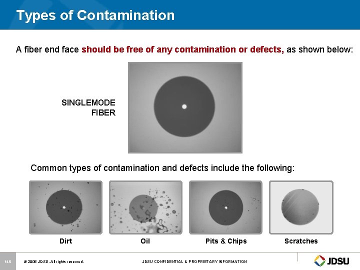
Types of Contamination A fiber end face should be free of any contamination or defects, as shown below: SINGLEMODE FIBER Common types of contamination and defects include the following: Dirt 146 © 2005 JDSU. All rights reserved. Oil Pits & Chips JDSU CONFIDENTIAL & PROPRIETARY INFORMATION Scratches

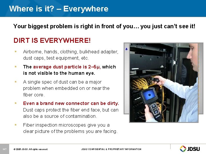
Where is it? – Everywhere Your biggest problem is right in front of you… you just can’t see it! DIRT IS EVERYWHERE! 147 § Airborne, hands, clothing, bulkhead adapter, dust caps, test equipment, etc. § The average dust particle is 2– 5µ, which is not visible to the human eye. § A single spec of dust can be a major problem when embedded on or near the fiber core. § Even a brand new connector can be dirty. Dust caps protect the fiber end face, but can also be a source of contamination. § Fiber inspection microscopes give you a clear picture of the problems you are facing. © 2005 JDSU. All rights reserved. JDSU CONFIDENTIAL & PROPRIETARY INFORMATION

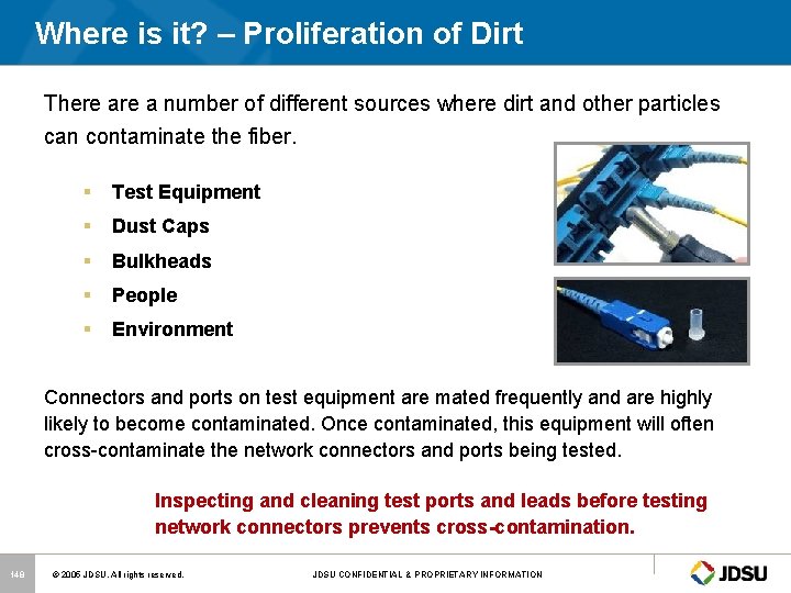
Where is it? – Proliferation of Dirt There a number of different sources where dirt and other particles can contaminate the fiber. § Test Equipment § Dust Caps § Bulkheads § People § Environment Connectors and ports on test equipment are mated frequently and are highly likely to become contaminated. Once contaminated, this equipment will often cross-contaminate the network connectors and ports being tested. Inspecting and cleaning test ports and leads before testing network connectors prevents cross-contamination. 148 © 2005 JDSU. All rights reserved. JDSU CONFIDENTIAL & PROPRIETARY INFORMATION

Conclusion § If we want our telecommunications networks to be as reliable/available as the telephony business at 99. 98%, we must; – – Stay up with technology Have contingency plans for everything Train our employees Utilize equipment that will quickly characterize and separate real problems from insignificant events – Be Proactive instead of Reactive! 149 © 2005 JDSU. All rights reserved. JDSU CONFIDENTIAL & PROPRIETARY INFORMATION

Thank You ! Mark Ortel Sales Support Engineer Cable Networks Division www. jdsu. com SCTE Chapter 150 © 2005 JDSU. All rights reserved. JDSU CONFIDENTIAL & PROPRIETARY INFORMATION