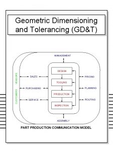
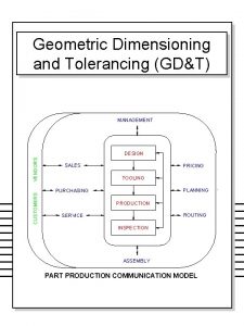
Geometric Dimensioning Tolerancing Presentation OLCAY ENEL Olcay ENEL


- Slides: 99

Geometric Dimensioning & Tolerancing Presentation OLCAY ŞENEL Olcay ŞENEL • AMEC- APRIL 2013 AMEC-April 2013

This Presentation outlines including 1. What is GD&T 2. Model Base Definition -MBD- and Tolerancing methodology at the different production levels. 3. Why, Where and When should GD&T be used 4. GD&T helps improve quality, reduces product cycle time, and cut costs 5. GD&T Characteristics and Symbology 6. New Changes in the ASME Y 14. 5 -2009 standard Olcay ŞENEL AMEC-April 2013

1. What is GD&T Olcay ŞENEL AMEC-April 2013

The Geometric Characteristic Symbols Type of Tolerance Characteristic Symbol Control Straightness (Surface) For Individual Features For Individual or Related Features Form Profile Orientation For Related Features Location Runout Straightness (Axis) 2 D Flatness (Surface) 3 D Flatness (median line) 3 D Circularity 2 D Cylindricity 3 D Profile of a Line 2 D Profile of a Surface 3 D Angularity 3 D Perpendicularity 3 D Parallelism 3 D Position 3 D Concentricity 3 D Symmetry 3 D Circular Runout 2 D Total Runout 3 D * Arrowhead(s) may be left unfilled. Olcay ŞENEL AMEC-April 2013

What Is GD&T? Geometric Dimensioning and Tolerancing (GD&T) is the internationally recognized engineering drawing language used in describing 3 -dimensional part geometry and allowable tolerance variations on an engineering drawing. This language has been developed and refined over the past 60 years to help improve quality, reduce product cycle time, and cut costs using a philosophy of 3 -dimensional assembly variation combined with accepted manufacturing principles. The GD&T system of tolerancing uses an organized, methodical, and realistic approach in the determination, evaluation, specification, and verification of the product dimensions and allowable production tolerances. In particular, it is a means of GD&T a drawing with respect to actual function or relationship of part features which can be most economically produced. Function and Relationship are the key words. Olcay ŞENEL AMEC-April 2013

The figure below illustrates a typical GD&T application. To the novice drawing user, the system seems a bit intimidating. What do all of these funny symbols mean? Do we really need them on the drawing? What will GD&T do for me? Typical GD&T Drawing Produced in Accordance With ASME Y 14. 5 M-1994 GD&T Allows the Designer To “Tell the Whole Story” About the Part Olcay ŞENEL AMEC-April 2013

A Brief History of GD&T 1905 – William Taylor was granted a patent for his concept in making full-form GO and NO-GO gages. This concept, known as the Envelope Principle, serves as the core of modern day geometric tolerancing. 1938 – Stanley Parker of the Royal Torpedo Factory in Alexandria, Scotland is credited with the creation of the “Theory of True Position. ” The system used the concept of locating round holes in round tolerance zones rather than the traditional square zones. 1940 – “Chevrolet Draftsman’s Handbook” introduces the Maximum Material Condition Principle to allow additional location tolerance for a hole if it is produced at a larger size. 1949 – First standardized concepts of GD&T came as a crude system defined in several paragraphs of MIL-STD-8. The system expanded with each revision of the standard; adding new symbols, concepts, rules, and tolerancing principles. 1966 – First unified American National Standard devoted solely to the subject of GD&T was released as USASI Y 14. 5 -1966 and was quickly adopted as the mainstay for tolerance applications on all military contracts. 1973 and 1982 – ANSI Y 14. 5 updated and expanded to keep pace with changing technology and manufacturing methods. New symbols are added as well as expanded tolerancing methods. Olcay ŞENEL AMEC-April 2013

Since the initial release of Y 14. 5, the standard has continued to expand tolerancing principles have been refined in response to changes and advancements in manufacturing techniques and technology. The latest American National Standards related to geometric tolerancing are: · ASME Y 14. 5 M-1994 - Dimensioning and Tolerancing · ASME Y 14. 5. 1 M-1994 - Mathematical Principles of Dimensioning and Tolerancing Principles · ASME Y 14. 5. 2 M-1996 - Certification of Geometric Tolerancing Professionals · ASME Y 14. 8 M-1996 - Castings and Forgings (illustrates unique GD&T applications for castings and forgings) · ASME Y 14. 5 -2009 - Dimensioning and Tolerancing The geometric tolerancing system defined by these standards is used by most major companies in the U. S. International standardization in the area of GD&T has occurred concurrently with the development of U. S. standards, making GD&T the most widely accepted system for part definition throughout the world. Olcay ŞENEL AMEC-April 2013

The History of Product Definition Olcay ŞENEL AMEC-April 2013

2. Model Base Definition -MBD- and Tolerancing methodology at the different production levels. Olcay ŞENEL AMEC-April 2013

MBD - Model Base Definition Olcay ŞENEL AMEC-April 2013

MBD - Model Base Definition Olcay ŞENEL AMEC-April 2013

Key Characteristics Process & Tolerancing Olcay ŞENEL AMEC-April 2013

Key Characteristics Levels & Tolerancing PKC definitions are needed those are defined in AC level or section level AKC cascadings are determined by tolerance analysis (1 D, 2 D, 3 D) Olcay ŞENEL AMEC-April 2013

Key Characteristics Levels & Tolerancing Sub-AKC cascading is determined by tolerance analysis (1 D, 2 D, 3 D) MKC cascading is determined by tolerance analysis (1 D, 2 D, 3 D) Olcay ŞENEL AMEC-April 2013

PKC - Performance Key Characteristic Olcay ŞENEL AMEC-April 2013

AKC - Assembly Key Characteristic ASFX Positioning tolerance of Panel & Rib Tool Positioning Tolerance: ± 0. 20 Olcay ŞENEL AMEC-April 2013

MKC - Manufacturing Key Characteristic ELEMENTARY PART TOLERANCE CAPABILITY VALUES Olcay ŞENEL AMEC-April 2013

MKC&T ELEMENTARY PART TOLERANCE CAPABILITY VALUES Olcay ŞENEL AMEC-April 2013

MKC&T ELEMENTARY PART TOLERANCE CAPABILITY VALUES Olcay ŞENEL AMEC-April 2013

MKC&T ELEMENTARY PART TOLERANCE CAPABILITY VALUES Olcay ŞENEL AMEC-April 2013

MKC&T ELEMENTARY PART TOLERANCE CAPABILITY VALUES Olcay ŞENEL AMEC-April 2013

MKC&T ELEMENTARY PART TOLERANCE CAPABILITY VALUES Olcay ŞENEL AMEC-April 2013

Assembly Jig KC&T MASTER DATUM DEFINITIONS IN ASSEMBLY JIG Olcay ŞENEL AMEC-April 2013

Assembly Jig KC&T MASTER DATUM DEFINITIONS IN ASSEMBLY JIG A DATUM DEFINITION IN ASSEMBLY JIG: Middle Line Going Through A 1 and A 2 Hinge Fitting 1 Hinge Fitting 5 Olcay ŞENEL AMEC-April 2013

Assembly Jig KC&T MASTER DATUM DEFINITIONS IN ASSEMBLY JIG DATUM C DEFINITION IN ASSEMBLY JIG: Point C going intersection between C 1 and C 2 Olcay ŞENEL AMEC-April 2013

Assembly Jig KC&T 0. 20 A A 0. 20 Tool Positioning Tolerance A 0. 20 A A : ± 0. 10 Broaching Tolerance (Pin – Bush/Bearing Interface): ± 0. 05 ± 0, 15 mm “Adaptor parts” will be installed in each “supporting tool detail”. Laser tracker will be used to position “supporting tool details” precisely inline with each other. Then the “supporting tool details” will be assembled to the base. If hinge line is out of tolerance, reaming will be performed as a rework operation with PMMR’s. Olcay ŞENEL AMEC-April 2013

3. Why, Where and When should GD&T be used Olcay ŞENEL AMEC-April 2013

Why and When should GD&T be used FIRST AND FOREMOST ITS USE SAVES MONEY • It saves money directly by providing for maximum producibility of the part through maximum production tolerances. it provides “ bonus” or extra tolerances in many cases. • It ensures that design dimensional and tolerance requirements, as they relate to actual function are specifically stated and thus carried out. • It adapts to, and assists computerization technique in Design, Manufacturing and Inspection. • When Part features are critical to function or interchangeability, • When Functional gaging technigues are desirable, • GD&T is a common language that may be used to improve communication between design, quality, manufacturing, suppliers and customers. Olcay ŞENEL AMEC-April 2013

Even the Simplest Part Provides More Than One Interpretation! Does this on the drawing: . . . or this? 1. 26 1. 24 Mean this? . . . or this? Part checks good this way. . . Without Specific Direction on the Engineering Drawing, It’s Not Clear as to Which Interpretation Is Desired Olcay ŞENEL AMEC-April 2013

Indicating a Dimensional Origin Occasionally a condition will arise where it is desired to indicate that a dimension originates from one surface, and not the other. This may be the case for the part shown below. Functionally, the part mounts on the short surface and the long surface must clear the electrical bus bar. Part Function Part is a safety guard for an electrical bus bar Olcay ŞENEL AMEC-April 2013

On the engineering drawing, the toleranced linear dimension defining the relationship between the two surfaces does not really specify how the dimension must be measured to ensure this functionality. As stated, the dimension offers two possible interpretations. A “rule-of-thumb” followed by many inspectors is to “set up on the longer surface” when making measurements where the drawing does not state otherwise. As you can see by the interpretations shown above, using the longer surface as the origin could result in a produced part which would not work in its intended application. Olcay ŞENEL AMEC-April 2013

A simplified means of indicating that the dimension be taken from one surface and not the other is applying a Dimension Origin Symbol to the dimension as shown below. The symbol, which replaces one of the arrowheads of the dimension line, informs the drawing user that the measurement must always be made from the short surface. The addition of the dimension origin symbol to the dimension callout helps to clarify the requirement. The dimension origin symbol serves as an “implied datum” for this specific dimension indicating that it be measured from one surface and not the other. The dimension origin symbol defines a simple one-to-one relationship between two individual features. But, parts usually cannot be so simply defined. Even if dimension origin symbols were used on every toleranced linear dimension, we would still have questions as to order of precedence for the features and functional orientation of the overall part. Olcay ŞENEL AMEC-April 2013

Why Do We Need GD&T? · Advances in industrial technology and increased use of computer manufacturing and inspection techniques has forced a need to be more exacting in the expression of design requirements - Since the computer can only define data in precise mathematical terms, the drawing specifications must be precise, with but one interpretation · Increased emphasis on diversification in manufacturing has mandated a need to communicate the total requirements for each part so that the drawing “stands on its own” - In today’s manufacturing world, a given part may be produced at one company, with its mating counterpart produced by another. No longer can we rely on the small shop techniques of “doctoring” parts to fit or using verbal communication to clarify what the drawing does not say - The plus-or-minus system of indicating part tolerances typically allowed bad parts to be accepted and good parts to be thrown in the trash bin. A better system was needed which corrected many of these problems. Olcay ŞENEL AMEC-April 2013

This on the drawing: A Does the part meet the “square within. 005” requirement as specified by the drawing? Note: . 009 Part To Be Square Within. 005 Produced Part. 003 Measurement Origin Olcay ŞENEL Measurement Origin AMEC-April 2013

Does this on the drawing: What is the correct interpretation for the 45° angle as specified by the drawing? A Mean this? . . . or this? What is this angle? Olcay ŞENEL AMEC-April 2013

Any of these controls now can be used to control the coaxiality of these diameters. This on the drawing: Note: Diameters To Be Concentric Within. 003 Which diameter(s) is to be used as the starting point in verifying the “concentric within. 003” specification? Is the tolerance applied as plus-or-minus. 003, or is it. 003 total? Olcay ŞENEL AMEC-April 2013 A

A What is the correct method for measuring the 5. 000 and 6. 000 dimensions? How do we “measure” to a feature that is not even on the part? Olcay ŞENEL AMEC-April 2013

How GD&T Works There are numerous advantages to using the geometric tolerancing system over the old “plus-or-minus” method. These advantages can most readily be seen by comparing the manner in which holes were located in the past with the geometric tolerancing method of locating holes. The drawing below illustrates a part in which we wish to locate a single hole. Using the coordinate (plus-or-minus) method of tolerancing the location of the hole, a tolerance is applied to each dimension defining its location from the edges. Olcay ŞENEL AMEC-April 2013

The coordinate (plus-or-minus) method of tolerancing allows the axis of the hole to move “plus” something and “minus” something in both the “X” direction and “Y” direction; creating a “zone of tolerance” in which the hole axes must lie. A Closer Look: Upon closer examination of this square tolerance zone, notice that a hole located in the corner of the square would be further from the ideal or “perfect” location defined by the dimensions than would a hole located across the flats. This is not very logical; to allow more location in one direction than the other for a round hole. The hole should be allowed the same amount of tolerance in any direction measured. Olcay ŞENEL Even though it is closer to the basic center, this hole would be rejected since it falls outside the tolerance zone AMEC-April 2013 Hole axis is allowed to be in the corner of the tolerance zone

Another problem with the plus-or-minus method of tolerancing is that it is a 2 D system used to locate a 3 D part feature. The coordinate system tells us where the hole axis lies in an “X” direction and a “Y” direction, but it does not control what happens with the hole in the “Z” direction. A bolt or mating pin going into this hole mates with the entire hole, not just at one surface. It makes more sense; a 3 D hole must be located using a 3 D tolerance. Converting from a square zone to a round zone increases the available hole location tolerance by 57% All hole axes must lie within a tolerance zone which is the same distance from the basic center in any direction measured If hole axis is allowed to be in the corner of the square zone, then it should be allowed to fall anywhere inside a zone that is equal to that distance from the basic center A round hole should have a round tolerance zone and, since the hole is three-dimensional, the tolerance zone for locating it should be three-dimensional as well. But, with the old plus-orminus system, there was no way to state a round, three-dimensional tolerance zone on the drawing. This is where the geometric tolerancing system comes in. Olcay ŞENEL AMEC-April 2013

With geometric tolerancing, the tolerance is associated with the feature being located; not the dimension. This is accomplished by placing a rectangular box beneath the hole size callout which contains the tolerance information. This box is referred to as a “Feature Control Frame. ” . 500 ±. 003 The tolerance defining the Ø. 014 location for the hole is stated in a feature control frame associated with the hole callout 1. 500 2. 000 The feature control frame provides specific tolerance information for features with which it is associated. It provides the drawing user with clear instructions as to the type of control being applied, how much tolerance is allowed, and the relationship to other part features where applicable. Olcay ŞENEL AMEC-April 2013

Olcay ŞENEL AMEC-April 2013

Size – The First Order of Control The first order of part control comes with allowable variations as defined by the limits of size specified for individual features. Where only a tolerance of size is specified, the limits of size of an individual feature prescribe the extent within which variations of geometric form, as well as size, are allowed. This combined size/form control is achieved by the requirements for individual features of size as set forth under Rule No. 1 – The Limits of Size. Olcay ŞENEL AMEC-April 2013

Features of Size – Material Condition In geometric tolerancing, it is often desirable to apply the tolerance when a feature is produced at a specific size. Typically, the size extremes (largest or smallest) represent the “worst case” mating size for the feature and are used as the basis for tolerance analysis. Several terms have been developed to describe the various conditions of size used in applying geometric tolerances. These terms are: Maximum Material Condition (MMC) Least Material Condition (LMC) Regardless of Feature Size (RFS) These terms are commonly used when describing the specific size conditions for applying geometric tolerances. Olcay ŞENEL AMEC-April 2013

How GD&T provides “ bonus” or extra tolerances in many cases. Maximum Material Condition (MMC) The condition where a feature of size contains the maximum amount of material allowed by its size tolerance. (For example, smallest size hole or the largest size pin) Least Material Condition (LMC) The condition where a feature of size contains the least amount of material allowed by its size tolerance. (For example, largest size hole or the smallest size pin) Regardless of Feature Size (RFS) A term used to describe a feature of size, at any increment of size, within it’s size tolerance. (Actual mating size) Olcay ŞENEL AMEC-April 2013

Identifying MMC/LMC – Exercise No. 1 Identify the Applicable MMC or LMC for the Indicated Features LMC 2 X Ø. 375 ±. 025 1. 740 LMC 1. 750 MMC . 350 1. 617 Ø 1. 625 ±. 008 MMC . 887 Ø. 875 ±. 012 +. 000 -. 010 N/A 3 X Ø. 250 ±. 004 1. 08 ±. 02 LMC . 254 Ø. 1125 ±. 0003 MMC 2. 28 2. 24 5. 75 ±. 03 MMC 2. 28 LMC Olcay ŞENEL 5. 72 AMEC-April 2013 . 1122

4. GD&T helps improve quality, reduces product cycle time, and cut costs Olcay ŞENEL AMEC-April 2013

Rule No. 1 – The Limits of Size Olcay ŞENEL AMEC-April 2013

The Envelope Principle Rule No. 1, in effect, specifies that the size tolerance specified for a feature controls the form of the feature as well as its size. This concept, known as the “Envelope Principle, ” is automatically invoked for features of size where ASME Y 14. 5 M 1994 has been indicated as the basis for tolerance interpretation. The Envelope Principle, also known as the “Taylor Principle, ” is based on a concept developed by William Taylor in 1905. Mr. Taylor was granted a patent for this concept in making full-form GO and NO-GO gages; which are still used widely throughout industry today. This concept is automatically invoked for verification of features of size to support the use of GO and NOGO gages. Olcay ŞENEL AMEC-April 2013

Size Limit Measurement – Rule 1 This on the drawing: 1. 000. 990 Means this: . . . and this: Actual local size may not be less than. 990 at any cross section 1. 000 MMC ENVELOPE SURFACE TABLE The feature shall not violate an envelope of perfect form at the MMC limit of size. Olcay ŞENEL The feature must also be within the LMC limit of size through any cross section. (i. e. , caliper check) AMEC-April 2013

RFS Principle – (Implied) 4 X Ø. 260 ±. 003 Ø. 007 A B C 4. 50 ±. 03 2. 500 B 1. 000 1. 250 3. 250 5. 75 ±. 03 ACTUAL PRODUCED HOLE SIZE ALLOWABLE POSITIONAL TOLERANCE Ø. 257 (MMC) Ø. 258 Ø. 259 Ø. 260 Ø. 261 Ø. 262 Ø. 263 (LMC) Ø. 007 Ø. 007 . 188 ±. 010 A C The allowable positional tolerance for each hole is only the tolerance amount specified in the feature control frame. Geometric tolerances imply RFS for features of size where no modifier is shown in the feature control frame. This implied condition is defined by General Rule No. 2. Olcay ŞENEL AMEC-April 2013

MMC Principle – Symbol M 4 X Ø. 260 ±. 003 Ø. 007 M A B C 4. 50 ±. 03 2. 500 B 1. 000 1. 250 . 188 ±. 010 3. 250 5. 75 ±. 03 A C Size now interacts with location ACTUAL PRODUCED HOLE SIZE SPECIFIED POSITIONAL TOLERANCE Ø. 257 (MMC) Ø. 258 Ø. 259 Ø. 260 Ø. 261 Ø. 262 Ø. 263 (LMC) Ø. 007 Ø. 007 ADDITIONAL (BONUS) TOLERANCE Ø. 000 Ø. 001 Ø. 002 Ø. 003 Ø. 004 Ø. 005 Ø. 006 Olcay ŞENEL ALLOWABLE POSITIONAL TOLERANCE Ø. 007 Ø. 008 Ø. 009 Ø. 010 Ø. 011 Ø. 012 Ø. 013 The allowable positional tolerance for each hole is dependent on the actual size of the produced hole. Under the MMC Principle, more location tolerance is allowed when the hole departs from its MMC size limit. The amount of additional tolerance is equal to the amount of this departure. AMEC-April 2013

LMC Principle – Symbol L 4 X Ø. 260 ±. 003 Ø. 007 L A B C 4. 50 ±. 03 2. 500 B 1. 000 1. 250 . 188 ±. 010 3. 250 5. 75 ±. 03 A C Size interacts with location ACTUAL PRODUCED HOLE SIZE SPECIFIED POSITIONAL TOLERANCE ADDITIONAL (BONUS) TOLERANCE ALLOWABLE POSITIONAL TOLERANCE Ø. 263 (LMC) Ø. 262 Ø. 261 Ø. 260 Ø. 259 Ø. 258 Ø. 257 (MMC) Ø. 007 Ø. 000 Ø. 001 Ø. 002 Ø. 003 Ø. 004 Ø. 005 Ø. 006 Ø. 007 Ø. 008 Ø. 009 Ø. 010 Ø. 011 Ø. 012 Ø. 013 Olcay ŞENEL The allowable positional tolerance for each hole is dependent on the actual size of the produced hole. Under the LMC Principle, more location tolerance is allowed when the hole departs from its LMC size limit. The amount of additional tolerance is equal to the amount of this departure. AMEC-April 2013

Feature of Size – Exercise No. 2 This on the Drawing: Produced Part Is the Produced Part Acceptable as Specified by the Drawing? Olcay ŞENEL AMEC-April 2013

Feature of Size – Exercise No. 2 This on the Drawing: What if the hole was located here? Would the washer meet the drawing requirements? Produced Part . 200 Is the Produced Part Acceptable as Specified by the Drawing? Olcay ŞENEL AMEC-April 2013

. 028 at (M) +. 017 bonus from the hole 1. 270 MMC - 1. 240 actual size. 045 +. 030 bonus from the OD. 030 bonus . 075 total allowable This on the positional tol. Drawing: A . 507 actual size -. 490 MMC. 017 bonus Produced Part Lets add a datum and a geometric control. now - is the produced part acceptable as specified by the drawing? Remember – the tolerance is diametrical, the dimensions are radial Olcay ŞENEL AMEC-April 2013 2 X² + Y² 2. 032² +. 008² 2. 001024 +. 000064 2. 001088 2 X. 03298 = . 06596 actual positional location

Relationship Between Individual Part Features The limits of size as described under the provisions of Rule No. 1 only apply to individual features of size. Rule No. 1 does not control the interrelationship between the individual part features. Features shown perpendicular, coaxial, or otherwise geometrically related must be controlled to one another to avoid incomplete drawing requirements. In the geometric tolerancing system, these relationships are shown on the drawing through use of an appropriate geometric tolerance which interrelates the individual part features. Olcay ŞENEL AMEC-April 2013

Relationship Between Individual Features of Size This on the drawing: Allows this: Feature must fall within the limits of size per Rule No. 1 (2. 010 to 1. 990) Feature must fall within the limits of size per Rule No. 1 (1. 010 to. 990) Interrelationship of the implied 90° angle is governed by the general tolerances for angles usually found in the drawing’s title block Olcay ŞENEL AMEC-April 2013

Feature of Size – Exercise No. 3 2 X Ø. 386 +. 008 -. 000 4. 000 ±. 025 3. 375 PART A 2. 700 ±. 025 2 X 1. 300 . 530 -. 550 1. 256 +. 010 -. 000 . 500 ±. 015 PART B +. 000 1. 250 -. 010 . 510. 490 2 X. 650 1. 000 ±. 025 . 500 ±. 015 3. 375 4. 000 ±. 025 2 X Ø. 386 +. 008 -. 000 Perform a Tolerance Stack-Up To Assure That Part “B” Will Always Fit Into Part “A” Olcay ŞENEL AMEC-April 2013

Feature of Size – Exercise No. 3 2 X Ø. 386 4. 000 ±. 025 3. 375 PART A +. 008 -. 000 2. 700 ±. 025 2 X 1. 300 CF . 530 -. 550 B PART B CF B C +. 010 1. 256 -. 000 A C. 500 ±. 015 C +. 000 1. 250 -. 010 A. 510. 490 2 X. 650 1. 000 ±. 025 . 500 ±. 015 3. 375 4. 000 ±. 025 2 X Ø. 386 +. 008 -. 000 Perform a Tolerance Stack-Up To Assure That Part “B” Will Always Fit Into Part “A” Olcay ŞENEL AMEC-April 2013

5. GD&T Characteristics and Symbology Olcay ŞENEL AMEC-April 2013

General Tolerancing Symbols DIAMETER SYMBOL The symbolic representation for a diameter is shown at left. The symbol always precedes the size dimension indicating the diameter or tolerance zone size. SQUARE SYMBOL The symbolic representation for a square feature is shown at left. The symbol always precedes the size dimension indicating the size of the square feature. RADIUS SYMBOL The symbolic representation for a radius is shown at left. This specifies a zone defined by two arcs (the minimum and maximum radii) within which the surface must lie. The symbol always precedes the size dimension for the radius. CONTROLLED RADIUS SYMBOL The symbolic representation for a controlled radius is shown at left. This specifies a zone defined by two arcs (the minimum and maximum radii) within which the surface must lie. Additionally, the surface must be a faired curve without flats and/or reversals. The symbol always precedes the size dimension for the radius. Olcay ŞENEL AMEC-April 2013

General Tolerancing Symbols (Cont’d) COUNTERSINK SYMBOL The symbolic representation for a countersink is shown at left. The symbol always precedes the dimensions defining the size and included angle of the countersink. Replaces past practices of specifying as “CSK” or “C’SINK” on drawings. COUNTERBORE OR SPOTFACE The symbolic representation for a counterbore or spotface is shown at left. The symbol always precedes the dimensions defining the size of the counterbore or spotface. Depth may be indicated as the remaining material (left) or using the depth symbol. Where no depth is indicated (for a spotface) the depth is assumed to be the minimum depth necessary to achieve 100% clean-up for the surface. Olcay ŞENEL AMEC-April 2013

General Tolerancing Symbols (Cont’d) DEPTH SYMBOL The symbolic representation for indicating the depth of a feature (such as a blind hole or counterbore depth) is shown at left. The symbol always precedes the size dimension indicating the depth for the feature. SPHERICAL DIAMETER OR SPHERICAL RADIUS The symbolic representation for indicating the spherical diameter or a spherical radius is shown at left. The symbol always precedes the size dimension for the feature. Olcay ŞENEL AMEC-April 2013

General Tolerancing Symbols (Cont’d) REFERENCE DIMENSION The symbolic representation for indicating a reference dimension (or other reference data) is shown at left. The reference dimension (or data) is enclosed in parentheses. BASIC DIMENSION The symbolic representation for indicating a basic dimension is shown at left. Basic dimensions have no tolerance. ALL AROUND ALL OVER (see ASME Y 14. 5 -2009) SYMBOLS The symbolic representation for indicating a tolerance “all around” a feature is shown at left. DIMENSION ORIGIN SYMBOL The symbolic means for indicating that a dimension originates from a specific surface is illustrated at left. Olcay ŞENEL AMEC-April 2013

The Geometric Characteristic Symbols Type of Tolerance Characteristic Symbol Control Straightness (Surface) For Individual Features For Individual or Related Features Form Profile Orientation For Related Features Location Runout Straightness (Axis) 2 D Flatness (Surface) 3 D Flatness (median line) 3 D Circularity 2 D Cylindricity 3 D Profile of a Line 2 D Profile of a Surface 3 D Angularity 3 D Perpendicularity 3 D Parallelism 3 D Position 3 D Concentricity 3 D Symmetry 3 D Circular Runout 2 D Total Runout 3 D * Arrowhead(s) may be left unfilled. Olcay ŞENEL AMEC-April 2013

GD&T Symbols – Exercise No. 1 Draw the symbolic representation for each of the following: FLATNESS PROFILE OF A SURFACE STRAIGHTNESS PARALLELISM COUNTERSINK SYMMETRY CIRCULARITY POSITION TOTAL RUNOUT Olcay ŞENEL PROFILE OF A LINE CYLINDRICITY COUNTERBORE DIAMETER ANGULARITY DEPTH CIRCULAR RUNOUT PERPENDICULARITY BASIC DIMENSION AMEC-April 2013

Feature Control Frame Construction Geometric Characteristic Symbol Primary Datum Secondary Datum Tertiary Datum Ø. 006 M A B M C Tolerance Zone Shape Datum Modifier Feature Tolerance Modifier The type of control being applied is indicated using one of the fourteen geometric characteristic symbols. Only one geometric characteristic symbol is allowed in each feature control frame. Each feature control frame defines one set-up, one tolerance, one requirement, one thing to do. If there are two different tolerance requirements for the same feature, then there must be two feature control frames defining those requirements. Olcay ŞENEL AMEC-April 2013

Feature Control Frame – Exercise No. 2 1. Construct a feature control frame to specify a surface to be flat within. 002 total. 2. Construct a feature control frame to make a hole parallel within. 004 at MMC in relation to datum plane A. 3. Construct a feature control frame to locate a slot within. 010 at MMC in relation to primary datum G, secondary datum F, and tertiary datum D. 4. Construct a feature control frame to locate a hole within Ø. 015 at MMC in relation to primary datum plane A, secondary datum B at MMC, and tertiary datum C. Additionally, the hole must be perpendicular within Ø. 004 at MMC in relation to primary datum plane A. Olcay ŞENEL AMEC-April 2013

Controlling a Planer Feature M 16. 2 +/-0. 1 or The placement of the Feature Control Frame is very important. Depending on where it is placed on the drawing, the control requirement changes. As shown above in Blue, the feature control frame is attached to the size of the tab. Here the perpendicularity tolerance controls the centerplane of the tab. The Red feature control frame is attached to the extension line. Here the perpendicularity tolerance controls the side of the tab. Olcay ŞENEL AMEC-April 2013

GEOMETRIC TOLERANCING APPLICATION – HUB INTERPRET DRAWING PER ASME Y 14. 5 M-1994 Olcay ŞENEL AMEC-April 2013

Tolerance Modifiers Ø. 258 -. 272 Ø. 005 M A B C The absence of a modifier invokes the Regardless of Feature Size (RFS) Principle. The tolerance specified in the feature control frame applies at any increment of size for the produced feature. No additional tolerance is allowed. M L Invokes the Maximum Material Condition (MMC) Principle. The tolerance specified in the feature control frame applies when the feature is produced at its maximum material limit of size (smallest hole/largest pin). Additional tolerance is allowed as the feature departs its MMC limit toward LMC. The amount of additional tolerance realized is equal to the amount of the departure from the MMC size limit. Invokes the Least Material Condition (LMC) Principle. The tolerance specified in the feature control frame applies when the feature is produced at its least material limit of size (largest hole/smallest pin). Additional tolerance is allowed as the feature departs its LMC limit toward MMC. The amount of additional tolerance realized is equal to the amount of the departure from the LMC size limit. Note Tolerance modifiers may only be applied to geometric tolerances controlling the center, axis, or median plane of a feature of size. Tolerance modifiers are not applicable to planar features. Olcay ŞENEL AMEC-April 2013

Rule No. 2 – All Applicable Geometric Tolerances For all applicable geometric tolerances, RFS is assumed to apply where no material condition modifier is shown with the feature tolerance, datum reference(s), or both as applicable. NOTE: Profile, concentricity, symmetry, and runout are applicable only on an RFS basis and cannot be modified to MMC or LMC. RFS IMPLIED Rule No. 2 a – Alternate Practice for Position Tolerances Under ANSI Y 14. 5 M-1982, specifying RFS for a positional tolerance required the use of an RFS material modifier symbol with the tolerance or datum as applicable. This practice is still allowed under Rule No. 2 a as shown below. For tolerances of POSITION, RFS may be specified in the feature control frame with respect to the feature tolerance, datum reference(s), or both as applicable. Ø. 005 S A BS Olcay ŞENEL (Only applicable for location tolerances) AMEC-April 2013

6. New Changes in the ASME Y 14. 5 -2009 Standard Olcay ŞENEL AMEC-April 2013

Tolerance/Datum Feature Modifiers Modifying Symbols: Ø Per ASME Y 14. 5 - 2009 Revision Olcay ŞENEL AMEC-April 2013

Changes in the ASME Y 14. 5 Standard. Olcay ŞENEL AMEC-April 2013

MMC Virtual Condition Definition – A constant boundary generated by the collective effects of a size feature’s specified MMC size and the allowable geometric tolerance at MMC Virtual Condition is a mathematical boundary that simulates the worst-case mating size for the feature, in other words, how big or small the feature “acts” in relation to the datum or datum reference frame. Since virtual condition represents the worst-case of the feature(s), it is useful for: · Evaluating interchangeability between mating parts · Determining gage feature sizes Olcay ŞENEL AMEC-April 2013

Internal Feature – MMC Virtual Condition External Feature – MMC Virtual Condition Olcay ŞENEL AMEC-April 2013

4 X Ø. 325 ±. 003 Ø. 012 M A B C Design and sketch a simple fixed-limit functional gage to verify the positional tolerance for the holes. 5. 75 ±. 03 3. 000 B 1. 750 2. 000 4. 125 8. 25 ±. 03 . 188 ±. 010 A C 4 X Ø. 310 VC C 2. 000 4. 125 Notice that the pins protrude all the way through the part. They have to verify the full length of the hole. 3. 000 1. 750 B Olcay ŞENEL A AMEC-April 2013

MMC Virtual Condition – Exercise No. 1 Calculate the MMC Virtual Condition for the mating parts below to assure that the parts will assemble. . 807 -. 803. 004 . 803. 002 +. 002. 805 . 006 Olcay ŞENEL AMEC-April 2013

Tolerance Calculations – Exercise No. 2 Olcay ŞENEL AMEC-April 2013

1. 496 1. What is the MMC size for hole “D”? __________. 240 2. What is the LMC size of the. 25 feature? ________ . 030 3. What is the MMC positional tolerance for hole “D”? _______ 4. What is the allowable positional tolerance for the Ø. 198 holes when produced at: . 205 - . 198 (M) = . 007 + . 006 = . 013 Ø. 203 _____ . 011 Ø. 208 ______ . 016 Ø. 199 ______ . 007 Ø. 205 _____ . 192 5. What is the MMC Virtual Condition of the Ø. 198 holes? _____ 6. What is the MMC Virtual Condition of hole “D” in relation to datum 1. 488 plane A? ______ 7. Hole “D” is produced at a size of Ø 1. 499. The positional tolerance for the hole measured Ø. 032. The perpendicularity measured Ø. 012. Is NO – out of perpendicularity by. 001 this a good part? _____ If not, how can we fix it? Open the hole by. 001 or greater, up to 1. 504 to gain the bonus tolerance needed Olcay ŞENEL AMEC-April 2013

Datum Virtual Condition Rule-MMB Part Allowing Multiple Datum Shift Tolerances This rule applies to datum features subject to size variation referenced in a feature control frame on an MMC (or LMC) basis. This rule accounts for the relationship error between specified datum features that must be accounted for when establishing the datum reference frame. A VIRTUAL CONDITION exists for a secondary or tertiary datum feature of size where its axis or center plane is controlled by a geometric tolerance in relation to the higher precedence datums. In such cases, the datum feature applies at its VIRTUAL CONDITION even though it is referenced at MMC or LMC in the feature control frame. Olcay ŞENEL AMEC-April 2013

In the previous example, we saw how the datum shift is accommodated in a fixed-limit functional gage. But, we don’t make gages for every part, nor does specifying MMC on the datums necessitate the use of a gage in verifying the tolerances. The figure below illustrates another example of datum shift tolerance applied to a part. The three holes and the outside shape are located in relation to the face (primary datum A) and large diameter hole in the center (secondary datum B at MMC). Let’s see how the datum shift tolerance might be captured by the inspector without the use of a gage. Olcay ŞENEL AMEC-April 2013

The first thing the inspector would need to do would be to lock the part into the datum reference frame. This would be done by setting up to the face first (datum A primary) and centering on the large hole. The largest pins that could be placed inside the hole would represent its actual mating size. One of the three smaller holes is arbitrarily selected to anti-rotate the part. The final set-up might resemble the illustration below: Olcay ŞENEL AMEC-April 2013

From this “frame of reference, ” the inspector derives actual measurements in an “X” and “Y” direction, as well as produced sizes for the various holes so that we may determine the “bonus tolerance” allowed for each hole. The amount each hole was “off” from the basic dimensions defined by the engineering drawing are entered in the table as “X” and “Y” deviations. DATUM B VIRTUAL SIZE: DATUM B ACTUAL RELATED MATING SIZE: DATUM B SHIFT ALLOWANCE: INSPECTOR’S REPORT HOLE NO. HOLE MMC HOLE ACTUAL SIZE ALLOWED POSITIONAL TOLERANCE “X” DEV. 1 +. 003 -. 005 2 +. 003 3 “Y” DEV. ACC OR REJ DATUM EVALUATION ACC OR REJ . 000 +. 004 X -. 002 But, what we really want to know is if the holes fell in a round tolerance zone, not an “X” and “Y” measurement. This is where a paper or “soft” gage may be used. Olcay ŞENEL AMEC-April 2013

2 1. 002. 004 3 . 006. 008. 010. 012 Olcay ŞENEL AMEC-April 2013

True Position Polar Grid . 002. 004. 006. 008. 010. 012 Olcay ŞENEL AMEC-April 2013

We begin analysis of the hole locations using a Cartesian coordinate grid which represents the inspector’s measurements. The center of this grid represents the basic or true position for each of the holes, as well as representing the center of datum feature B. We plot their location on the grid. Using the data from the inspector’s report, the information is transferred to the grid, plotting the X and Y deviations from the inspector’s measurements. Once the holes have been plotted onto the coordinate grid, a polar grid (representing the round positional tolerance zones) is laid over the coordinate grid, with the centers of the two grids aligned. We then look to see if each plotted hole falls inside its total allowable position tolerance. If all the holes fall inside their zones, the part is good and the inspector is done. But, for our example, note that hole #2 falls well outside the Ø. 010 positional tolerance allowed for a Ø. 483 hole when the polar grid is centered on the coordinate grid. Even opening the hole up to its largest size of Ø. 484 would not get us enough bonus tolerance to make the part good. But, is the part really bad? When we verified that the holes were inside their tolerance “rings, ” remember that the two grids were aligned, with one on the center of the other (RFS). But, the actual mating size of datum feature B allows a Ø. 004 shift tolerance for the datum. This allowable shift may be translated to the hole verification by moving the polar grid such that the center of the coordinate grid remains inside a Ø. 004 zone when measuring the holes. When shifting the polar grid in this manner, we must make sure that all of the holes fall within their respective tolerance zones simultaneously. Olcay ŞENEL AMEC-April 2013

Olcay ŞENEL AMEC-April 2013

True Position Polar Grid Olcay ŞENEL AMEC-April 2013

Rotational “Shift” Tolerance Looking again at the cylindrical part, we see that the hole pattern must now be oriented with relation to the slot, which is referenced on an MMC basis. When simulating the slot, we would use a virtual condition width as the true geometric counterpart of the datum feature. As the slot departs its virtual condition (is produced at a larger size and/or uses less of its allowed positional tolerance), the entire hole pattern, as a group, is allowed to rotate in relation to the true geometric counterpart of datum feature C in verifying the position for the hole pattern. Olcay ŞENEL AMEC-April 2013

Olcay ŞENEL AMEC-April 2013

Part Allowing Multiple Datum Shift Tolerances Using paper gage techniques, let’s take a look at the datum shift we might derive from a slot. The part below depicts a part similar to the previous example. The slot at MMC serves as the tertiary datum feature. In accordance with the datum virtual condition rule, the true geometric counterpart representing the slot is a virtual condition width. As with our previous example, the inspector would set up the produced part and collect the measurement data on the holes. This data is then delineated on the inspector’s report as shown on the following page. Olcay ŞENEL AMEC-April 2013

. 393. 399. 006 -. 005 “ “ “ Olcay ŞENEL “ “ “ +. 003 +. 005 +. 002 -. 005 R R AMEC-April 2013

. 393 Virtual Condition 2 1 3 4 Allowable Tolerance Zone Olcay ŞENEL AMEC-April 2013

When the holes are plotted onto the grid, we find that they all fall outside the Ø. 010 positional tolerance allowed for a Ø. 200 hole. Since datum B was produced at its virtual condition (thereby allowing no shift), the polar grid must remain on the center of the coordinate grid. Datum feature C (the slot) did depart from its virtual condition, allowing datum shift for the hole pattern in the form of rotation of the pattern. Calculations show that the slot departed its virtual condition by. 006; however, since the holes are closer to the center of rotation than is the slot, we may only realize a portion of the available. 006 shift. Since the holes lie roughly 80% the distance from the rotational center to the center of the slot, we can assume that we’ll only realize about 80% of the. 006 rotational shift tolerance, or about. 005. This means that we may rotate the part to the left or right by. 0025 in an attempt to get all the holes in the Ø. 010 positional tolerance zone. Olcay ŞENEL AMEC-April 2013

When the part is rotated to the right by. 0025, hole #1 moves to the right, hole #2 moves down, hole #3 moves to the left, and hole #4 moves up. After rotation, notice how the pattern moves closer to the center, resulting in all of the hole axes falling well inside the Ø. 010 positional tolerance zone. Olcay ŞENEL AMEC-April 2013
 Geometric dimensioning and tolerancing
 Murat olcay özcan
 Adrenomedüller
 Kırımlı fazilet olcay anadolu lisesi yüzdelik dilimi
 Previsin
 Tolerancing
 Zemax tolerancing
 Tolerancing definition
 Tolerancing
 Coordinate tolerancing
 Tolerancing
 Flatness geometric tolerance
 Tolerancing
 2018 geometry bootcamp answers
 Enel web edi
 Enel cont
 Enel sisma centro italia
 Enel green power catania
 Enel niin
 Arca enel meeting nazionali
 Generiraj oib
 Dimensioning standards
 Dimensioning guidelines
 Superimposed running dimensioning
 Superfluous dimensions
 Baseline dimensioning definition
 Orthographic projection
 Dimensioning techniques
 Progressive dimensioning
 Dimensioning adalah
 Dimensioning a cylinder
 Basic dimensioning rules
 Ansi dimensioning standards
 Dimensi gambar teknik adalah
 Glass box theory
 Progressive dimensioning in engineering drawing
 Dimensions
 What is a revolved section view? a revolved section view:
 Dimensioning
 Parallel dimensioning
 Dimensiona0
 Ordinate dimensioning rules
 Dimensioning components includes
 Micro dimensions of logistics
 Every family has its own rules
 Datum dimensioning method
 Dimensioning rules
 Reference dimension
 Architectural dimensioning rules
 Superfluous dimensions
 Wall thickness in floor plan
 Multiview drawing
 Dimensioning components includes
 In aligned system the dimensions are
 Dimension terminology
 Superimposed dimensioning
 Dimensioning components
 Brow presentation birth
 Vertex presentation
 Arithmetic sequence scavenger hunt
 Geometric and orientalizing art
 Camera models in computer vision
 Math 20-1 sequences and series
 Compare and classify geometric shapes
 Geometric context from a single image
 Geometric modeling in probability and statistics
 Geometric series test
 Geometric description of vectors
 Similarity in right triangles
 Geometric gradient formula
 Geometric sequence reflection
 Geometric image formation
 What is geometric probability
 Bicubic interpolation
 Class iv decay
 Staar blank place value chart
 Geometric sequence 6 18 54
 Compare geometric boundaries and antecedent boundaries.
 Concept map ng pananaliksik
 Geometric decay
 Arithmetic and geometric sequences
 Walk in graph theory
 Pattern formula nth term
 Distribusi geometrik
 Ib math
 Geometric quality
 Geometric distribution standard deviation
 Geometric titration
 Geometric transformation in digital image processing
 Aashto geometric design
 How to solve geometric sequence
 Recursive formula geometric
 What is unitary matrix
 Efflorescent powder in pharmaceutics
 Absorption unsharpness
 Arithmetically vs geometrically growth
 Ppt
Ppt Sn formula geometric sequence
 General pivot point rotation
 Geometric mass design
