Geometric Dimensioning Tolerancing GDT PDT 212 Feb 2020
 PDT 212 Feb. 2020 Learn, Understand, How to Use")
Geometric Dimensioning & Tolerancing (GD&T) PDT 212 Feb. 2020 Learn, Understand, How to Use the GD&T Max. Mat. Cond. to Avoid Inspection-Rejection of Entirely Functional Parts

Affected Areas Geometric Dimensioning &Tolerance Application Product Design Quality Control Manufacturing

Introduction

Introduction • A system of symbols developed and used to define part shapes, features form, orientation (Fiber-glass orientation example ), runout, profile and location. • A system based on function and interrelationship of mating features while keeping in mind manufacturing and inspection capabilities.
 is important. • To learn how to effectively")
Why Geometric Dimensioning & Tolerancing (GD&T) is important. • To learn how to effectively tolerance parts such that – The Parts Function Correctly – Fabrication Cost Is Kept To A Minimum • Apply Geometric Dimensioning & Tolerancing (GD&T); in particuluar – Position, Size – Flatness, Circularity – Perpendicularity, Parallelism

Geometric Dims & Tolerancing • Uses Standard Symbols To Indicate Tolerances That Are Based On The Feature’s Geometry. • Sometimes Called Feature-Based Dimensioning & Tolerancing, Or True Position Dimensioning & Tolerancing • Uses “Feature Control Frames” To Indicate Tolerance(s) • “State of the Art” for Tolerances

Geometric? • The “G” in GD&T refers to Geometric Forms – e. g. , plane, circle, cylinder, sq, or hexagon • Theoretically these forms are Perfect – but any REAL Form will be Imperfect • In GD&T The Limits of Real Variation (tolerance) are Specified by the Diameter/Width of a Planer, Cylindrical, Annular(ring-shape), or Spherical Zone

History of Tolerancing • In the 1800’s, manufacturing used the “cut & try, file & fit” approach. • The plus-minus (or coordinate) system of tolerancing was next developed. • In the 1900’s, the first GD&T standards came out to improve the quality & utility of engineering drawings. • In 1966, the united GD&T standard was published → ANSI - Y 14. 5 M

GD&T Definitions - 1 • Feature – General term applied to a physical portion of a part, such as a surface, hole, or slot. • Feature of Size (FOS) – One cylindrical or spherical surface, or a set of parallel surfaces, associated with a size dimension. (Can be external or internal) • Location Dimension – Locates the centerline or center plane of a part feature relative to: another part feature, centerline, or datum.
")
Example Feature of Size (FOS)

GD&T Definitions - 2 • Tolerance Zones – all geometric tolerances have imaginary tolerance zones that are the basis for acceptance or rejection of the product – have specific shapes depending on the geometric tolerance and feature being controlled • Actual Local Size – the value of any individual distance at any cross section of a feature of size (FOS)
 – a similar perfect feature")
GD&T Definitions - 3 • Actual Mating Envelope (AME) – a similar perfect feature counterpart that can be circumscribed/inscribed about/within the feature so it just contacts the surfaces at the highest & lowest points – It is derived from an actual part – Used When Calculating a “Bonus Tolerance”
. General Dimensioning, (2).")
Three Categories of Dimensioning can be divided into three categories: (1). General Dimensioning, (2). Geometric Dimensioning, and (3). Surface Texture.

Dimensions and Tolerances • Factors that determine the performance of a manufactured product, other than mechanical and physical properties, include : – Dimensions - linear or angular sizes of a component specified on the part drawing – Tolerances - allowable variations from the specified part dimensions that are permitted in manufacturing

Dimensions A dimension is "a numerical value expressed in appropriate units of measure and indicated on a drawing and in other documents along with lines, symbols, and notes to define the size or geometric characteristic, or both, of a part or part feature" • The dimension indicates the part size desired by the designer, if the part could be made with no errors or variations in the fabrication process

Dimensions Example of Dimensions The dimensions of a rectangle are 4 m x 2 m` implies that the `length of the rectangle is 4 m and its width is 2 m

Tolerance A tolerance is "the total amount by which a specific dimension is permitted to vary. The tolerance is the difference between the maximum and minimum limits" • Variations occur in any manufacturing process, which are manifested as variations in part size • Tolerances are used to define the limits of the allowed variation • Precision is the degree of accuracy necessary to ensure the functioning of a part as intended. Tolerance is the allowable variation for any given size in order to achieve a proper function

TOLERANCING AND ENGINEERING STANDARDS Tolerancing is just like written languages. It has its own standards. There are to many standards like ANSI(Inch System), ISO (Metric System) etc. List of standards: ANSI B 4. 1, ANSI B 4. 2, ISO 286, ISO 1829, ISO 2768, EN 20286, JIS B 0401. In an assembly process the degree of "clearance" or "tightness" desired between mating parts is important.

Tolerancing Definitions • NOMINAL SIZE : The size used for general description. The term nominal size refers to the size of a part specified in the drawing for convenience to shop floor. Example; 7/8 inch Shaft, 25 mm Shaft etc.

Tolerancing Definitions • BASIC SIZE : The term basic size refers to the size from which the limits of size are derived by the application of tolerance (i. e. upper and lower deviation). The basic size or nominal size of a part is often the same and it is termed as zero line. The size used when the nominal size is converted to the decimal and from which deviation are made to produce limit dimension. Example: . 8750 inch shaft which is the basic size for a 7/8 inch nominal shaft.

Tolerancing Definitions ACTUAL SIZE : The term actual size referred to the actual measured dimension of a part. The difference between the basic size and the actual size should not exceed a certain limit, if so; it will disturb the interchangeability of assembly parts. •

• LIMIT DIMENSION : The Lower and Upper permitted sizes for a single feature dimension. 0. 500 -0. 506 inch where 0. 500 inch is the lower limit and 0. 506 inch upper limit dimensions • TOLERANCE : Tolerance is the allowable variation for any given size in order to achieve a proper function. Tolerance equals the difference between lower and upper limit dimensions. Example; for 0. 500 -0. 506 inch the tolerance would be 0. 006 inch
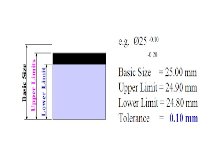

Example of Tolerance

Example of Tolerance

• Why is tolerancing necessary?

It is impossible to manufacture a part to an exact size or geometry Assemblies: Parts will often not fit together if their dimensions do not fall within a certain range of values Tolerances are needed to control the dimensions of any two mating parts so that any two parts may be interchangeable. Tolerances on parts contribute to the expense of a part, The smaller the tolerance the more expensive the part

• Types of tolerance

A Dimensional tolerance is the total amount a specific dimension is permitted to vary, which is the difference between maximum and minimum permitted limits of size. A Geometric tolerance is the maximum or minimum variation from true geometric form or position that may be permitted in manufacture. Geometric tolerance should be employed only for those requirements of a part critical to its functioning or interchangeability.

• How is tolerance specified?

Tolerances can be expressed in Several ways: General Tolerances A note may be placed on the drawing which specifies the tolerance for all dimensions except where individually specified TO BE HELD TO ± 0. 020 ALL DECIMAL DIMENSIONS ALL without DECIMAL DIMENSIONS TO BE HELD TO ± 0. 25 Specific Tolerances The tolerance for a single dimension may be specified with the dimension based on one of the following methods • Unilateral tolerance • Bilateral tolerance • Limit of Dimensions

Unilateral Tolerance System • In this type of system, the part dimension is allowed to vary on one side of the basic size, i. e. , either below or above it (refer figure b) • This system is preferred in an interchangeable manufacturing environment. This is because it is easy and simple to determine deviations. • This system helps standardize the GO gauge end. • This type of tolerancing method is helpful for the operator, as he has to machine the upper limit

Unilateral Tolerance System Of the shaft and the lower limit of the hole knowing fully well that still some margin is left for machining before the part is rejected. Examples of unilateral systems: Possible for a unilateral tolerance to be unbalanced – Ex: 2. 500 +0. 010, -0. 000

Bilateral Tolerance System • In this system, the dimension of the part is allowed to vary in both directions of the basic size • Limits of the tolerance lie on either side of the basic size. • Using this tolerance, as tolerance are varied, the type of fit gets varied. • When a machine is set for a basic size of the part then for mass production,

Bilateral Tolerance System The part tolerance are specified by the bilateral system. Example of bilateral system: Possible for a bilateral tolerance to be unbalanced – Ex: 2. 500 +0. 005, -0. 005

Limit Dimensions Permissible variation in a part feature size consists of the maximum and minimum dimensions allowed Example of limit dimension:
 Angular size dimension tolerance It specifies the allowable variation on the")
Dimensional Tolerances (Size) Angular size dimension tolerance It specifies the allowable variation on the size or gap formed by two angular elements of the shape. Curved dimension tolerance It is a tolerance on a dimension for a curved feature element measured along the entire path of the curve Diameter dimension tolerance It is the allowable variation of the size of a hole in a feature.
 Radial dimension tolerance It is the allowable variation for the radial")
Dimensional Tolerances (Size) Radial dimension tolerance It is the allowable variation for the radial distance from the center of a feature circular curve to a point on the curve. Location dimension tolerance It is the allowable variation in locating one feature of a point with respect to another. Angular dimension tolerance It defines the allowable variation in the angle between two elements of a feature.

Angular dimension tolerance

GD&T Advantages/Benefits • Repeatability of part orientation through the use of datum features. • Easy calculation of worst mating condition boundaries. • One standard used by all who create or interpret the engineering drawing. • Ease of part definition – geometric symbology. • Interchangeability of parts. • Cylindrical tolerance zone Vs rectangular/square tolerance

Envelope Principle • Proper Tolerancing establishes the ENVELOPE of the “perfect” part • Any deviation in FORM is acceptable, as long as it remains within the limits of size Required specs

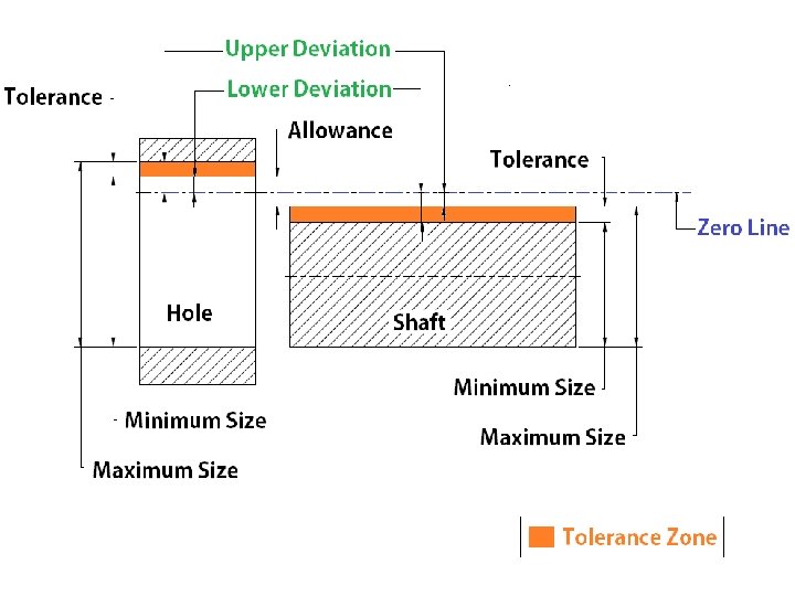
Limits of Size A variation in form is allowed between the least material condition (LMC) and the maximum material condition (MMC). Envelope Principle defines the size and form relationships between mating parts. Tolerance Zone

Limits of Size LMC & MMC • Clearance & Allowance ENVELOPE PRINCIPLE LMC CLEARANCE MMC ALLOWANCE

Limits of Size @ X-Section • The ACTUAL size of the feature at ANY CROSS SECTION must be within the size BOUNDARY. ØMMC ØLMC CROSS Sections are what we measure with Calipers or Micrometers

Limits of Size - Boundary No portion of the feature may be outside a PERFECT FORM BARRIER at maximum material condition (MMC). Most Common The Surface can also be ROUGH

GD&T Feature Control Frame Feature control frame

GD&T Feature Control Frame Feature control frame

GD&T Feature Control Frame § From ASME Y 14. 5 M-1994 • Some autocad (ACAD) Feature-Frames from Y 14. 51982

ANSI/ASME Y 14. 5 Rev. s § Responsibility for Maintenance of the Standard Shifted ANSI → ASME after the 1994 Version

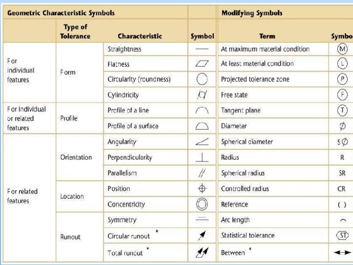
GD&T – Form & Profile GEOMETRIC CHARACTERISTIC CONTROLS 14 characteristics that may be controlled TYPE OF FEATURE TYPE OF CHARACTERISTIC SYMBOL TOLERANCE FLATNESS INDIVIDUAL (No Datum Reference) STRAIGHTNESS FORM CIRCULARITY CYLINDRICITY INDIVIDUAL or RELATED FEATURES LINE PROFILE SURFACE PROFILE

GD&T – Orientation, Run. Out, Location GEOMETRIC CHARACTERISTIC CONTROLS 14 characteristics that may be controlled TYPE OF FEATURE TYPE OF CHARACTERISTIC SYMBOL TOLERANCE PERPENDICULARITY ORIENTATION ANGULARITY PARALLELISM RELATED FEATURES (Datum Reference Required) CIRCULAR RUNOUT TOTAL RUNOUT CONCENTRICITY LOCATION POSITION SYMMETRY

Understanding Tolerance Zones • Traditional ± type of tolerancing describes a SQUARE zone for acceptable locations. • GD&T describes a CIRCULAR zone around theoretically exact location for the feature.

Basic Dimension • A theoretically exact dimension used to locate features in GD&T – The Dimension From Which the Limits of Variation are Derived • Basic dimensions are UNtoleranced – These NOMINAL Dims are THEORETICALLY Exact § Basic Dims Identified by Enclosure in a FRAME

Standard-Tolerance vs GD&T - 1 • Standard Tolerance Not Well Known: Actual hole-ctr distances, angle of hole-ctrs

Standard-Tolerance vs GD&T - 2 • GD&T Specs for Hole Centers and Angularity

Measure Position Tolerance . 500 § Acutually Need TWO Measurement Fixtures • A Go-Gage with Ø 0. 496 Pins • A No. Go-Gage with Ø 0. 504 Pins
 – largest acceptable size for external feature")
Material Conditions • Maximum Material Condition (MMC) – largest acceptable size for external feature – smallest acceptable size for internal feature – usually when geometric tolerances are applied at MMC the function is assembly • Least Material Condition (LMC) • function is usually to insure that a minimum distance on a part is maintained • Regardless of Feature Size (RFS) • often specified to insure symmetrical relationships. No “Bonus Tolerance” allowed

Material Conditions with more Details One of the benefits of GD&T is the ability to specify tolerances at various part sizes or MATERIAL CONDITIONS (MC). Modifiers >> Maximum Material Condition (MMC) >> Least Material Condition (LCM) >> Regardless of Feature Size (RFS)

Material Conditions M

Example of Material Conditions

Material Conditions RFS

Maximum Material Condition Given Holes at MMC § Smallest Holes at narrow Position accept 0. 493” Gage Pins Holes at LMC § Same Gage Pins for LMC Holes w/ Wide-Spacing allow Larger Pos Tol.
- Slides: 65