Engineering Drawing Dimensioning Session Aim Dimensioning of orthographic


 shows")


- Slides: 14
Engineering Drawing Dimensioning
Session Aim: Dimensioning of orthographic drawings. Learning Objectives: Correctly add dimensions to worksheet in workbook Production of a 3 rd angle projection drawing of a wooden block on an A 3 sheet including border and title block.
Dimensioning A dimensioned drawing should provide all the information necessary for a finished product or part to be manufactured. An example dimension is shown below. Dimensions are always drawn using continuous thin lines. Two projection lines indicate where the dimension starts and finishes. Projection lines do not touch the object and are drawn perpendicular to the element you are dimensioning. All dimensions less than 1 should have a leading zero. i. e. . 35 should be written as 0. 35
Types of Dimensioning • Parallel dimensioning consists of several dimensions originating from one projection line.
• Superimposed Running Dimensions • Superimposed running dimensioning simplifies parallel dimensions in order to reduce the space used on a drawing. The common origin for the dimension lines is indicated by a small circle at the intersection of the first dimension and the projection line.
Chain Dimensioning Combined Dimensions A combined dimension uses both chain and parallel dimensioning.
Dimensioning circles
Dimensioning Radii • All radial dimensions are proceeded by the capital R. (a) shows a radius dimensioned with the centre of the radius located on the drawing. (b) shows how to dimension radii which do not need their centres locating.
Tolerancing • It is not possible in practice to manufacture products to the exact figures displayed on an engineering drawing. The accuracy depends largely on the manufacturing process. A tolerance value shows the manufacturing department the maximum permissible variation from the dimension. • Each dimension on a drawing must include a tolerance value. This can appear either as: • a general tolerance value applicable to several dimensions. i. e. a note specifying that the General Tolerance +/- 0. 5 mm. • or a tolerance specific to that dimension
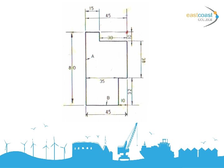
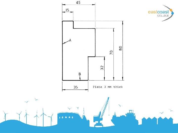
The sides marked A and B are known as DATUM faces. 1. DIMENSION LINES 2. PROJECTION LINES 3. ARROWHEADS 4. LEADER LINE 5. PROJECTION LINES 6. PROJECTION LINES 7. CROSSING EXTENSION LINES 8. DIMENSIONS 9. DIMENSION 10. DIMENSION
Dimensioning Most of the problems associated with dimensioning may be solved by the application of a few simple rules. • Dimensions should be placed on drawings so that they may be easily read. They must be clearly printed and placed outside the outline of the most appropriate view wherever possible. • The drawing must include the minimum number of dimensions necessary to manufacture the component and a dimension should not be stated more than once unless it aids communication. • It should not be necessary for dimensions to be deduced by the craftsman.
• Complete exercise