UNITII CO 2 Explain Geometric dimensioning and tolerancing


 Dimensioning and tolerancing shall be complete so there is full understanding of")
 Nonmandatory processing dimensions shall be identified by an appropriate note, such as")
 A zero basic dimension applies where axes, center planes, or surfaces are")


 limit and")


 between the hole and shaft")


- Slides: 68
UNIT-II CO 2 : Explain Geometric dimensioning and tolerancing GD&T
§ GD&T Stands for Geometric Dimensioning and Tolerancing. § GD&T is a symbolic language on engineering drawings that explicitly describes nominal geometry and its allowable variation. § GD&T is a more practical way to communicate engineering tolerances and designs. § Geometric tolerancing encourages a dimensioning philosophy called functional dimensioning. § Gives manufacturing more freedom in production while still maintaining critical dimensions.
http: //tolerancing. net/dimensioning/fundamental-dimensioning-rules. html Dimensioning is the process of applying measurements to a technical drawing. It is crucial to the whole process by which the designer will communicate the information required for the manufacture and verification of products. § (a) Each dimension shall have a tolerance, except for those dimensions specifically identified as reference, maximum, minimum, or stock (commercial stock size). The tolerance may be applied directly to the dimension (or indirectly in the case of basic dimensions), indicated by a general note, or located in a supplementary block of the drawing format. See ASME Y 14. 1 and ASME Y 14. 1 M.
§ (b) Dimensioning and tolerancing shall be complete so there is full understanding of the characteristics of each feature. Values may be expressed in an engineering drawing or in a CAD product definition data set. See ASME Y 14. 41. Neither scaling (measuring directly from an engineering drawing) nor assumption of a distance or size is permitted, except as follows: unidimensional drawings, such as loft, printed wiring, templates, and master layouts prepared on stable material, provided the necessary control dimensions are specified. § (c) Each necessary dimension of an end product shall be shown. No more dimensions than those necessary for complete definition shall be given. The use of reference dimensions on a drawing should be minimized. § (d) Dimensions shall be selected and arranged to suit the function and mating relationship of a part and shall not be subject to more than one interpretation. § (e) The drawing should define a part without specifying manufacturing methods. Thus, only the diameter of a hole is given without indicating whether it is to be drilled, reamed, punched, or made by any other operation. However, in those instances where manufacturing, processing, quality assurance, or environmental information is essential to the definition of engineering requirements, it shall be specified on the drawing or in a document referenced on the drawing.
§ (f) Nonmandatory processing dimensions shall be identified by an appropriate note, such as “NONMANDATORY (MFG DATA). ” Examples of nonmandatory data are processing dimensions that provide for finish allowance, shrink allowance, and other requirements, provided the final dimensions are given on the drawing. § (g) Dimensions should be arranged to provide required information for optimum readability. Dimensions should be shown in true profile views and refer to visible outlines. § (h) Wires, cables, sheets, rods, and other materials manufactured to gage or code numbers shall be specified by linear dimensions indicating the diameter or thickness. Gage or code numbers may be shown in parentheses following the dimension.
§ (i) A zero basic dimension applies where axes, center planes, or surfaces are shown coincident on a drawing, and geometric tolerances establish the relationship among the features. See para. 2. 1. 1. 4. § (j) Unless otherwise specified, all dimensions and tolerances are applicable at 20°C (68°F) in accordance with ANSI/ASME B 89. 6. 2. Compensation may be made for measurements made at other temperatures. § (k) Unless otherwise specified, all dimensions and tolerances apply in a free-state condition. For exceptions to this rule see paras. 4. 20 and 5. 5. § (l) Unless otherwise specified, all tolerances apply for full depth, length, and width of the feature. § (m) Dimensions and tolerances apply only at the drawing level where they are specified. A dimension specified for a given feature on one level of drawing (e. g. , a detail drawing) is not mandatory for that feature at any other level (e. g. , an assembly drawing). § Where a coordinate system is shown on the drawing, it shall be right-handed unless otherwise specified. Each axis shall be labeled and the positive direction shall be shown.
§ What is basic size of this component? The required size of the component, before the Limits are set, is called the Basic Size or Nominal Size.
§ Upper Deviation: The algebraic difference between the maximum limit of size (of either hole or shaft) and the corresponding basic size § Lower Deviation: The algebraic difference between the minimum limit of size (of either hole or shaft) and the corresponding basic size
§ Fundamental Deviation: It is one of the two deviations which is chosen to define the position of the tolerance zone.
§ Limit Dimensions - In limit dimensioning only the maximum and minimum dimensions are specified.
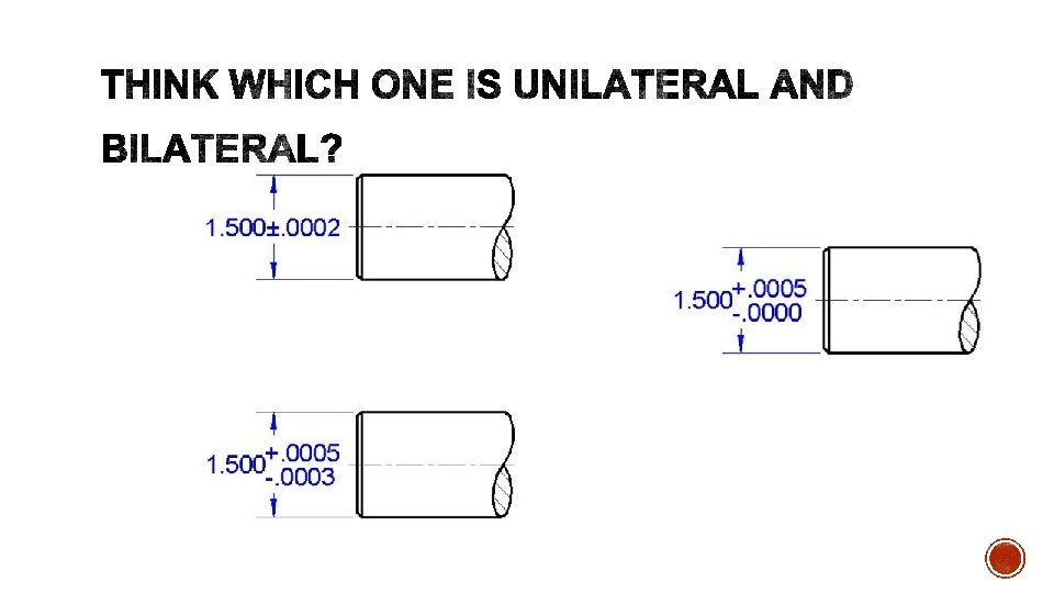
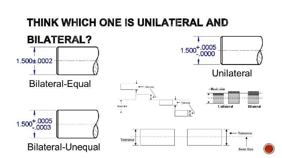
§ The term tolerance refers to the difference between the upper (maximum) limit and lower (minimum) limit of a dimension. § In other words, tolerance is the maximum permissible variation in a dimension. The tolerance may be of two types i. e. unilateral or bilateral.
What is tolerance?
http: //www. yourarticlelibrary. com/metrology/limits-fits-andtolerances-metrology/95253
§ The term tolerance zone refers to the zone between the maximum and minimum limit size.
Zone Line: § The term zero line refers to the straight line corresponding to the basic size, to which deviations and tolerances are referred. According to convention, the positive and negative deviations are shown above and below the zero line respectively. Deviation: § The term deviation referred to the algebraic difference between a size (actual size limits of size, etc. ) and the corresponding basic size. Upper-Deviation: § The term upper deviation refers to the algebraic difference between the maximum limit and the basic size. The upper deviation of a hole is demoted by a symbol ‘ES’ and of a shaft is denoted by a symbioses’.
Lower Deviation: § The term lower deviation refers to the algebraic difference between the minimum limit and basic size. The lower deviation of a hole is denoted by a symbol ‘EI’ and of a shaft it is denoted by a symbol ‘ei’. This is shown in Fig. 1. 55. Actual Deviation: § The term actual deviation refers to the algebraic difference between an actual size and the corresponding basic size. Mean Deviation: § The term mean deviation refers to the arithmetical mean between the upper and lower deviations. Fundamental Deviation: § The term fundamental deviation refers to the deviation, either the upper or the lower deviation, which is nearest one to the zero line for either a hole or a shaft. Fundamental deviation provides the position of the tolerance zone with respect to the zero line. The fundamental deviation is shown in fig. 1. 55.
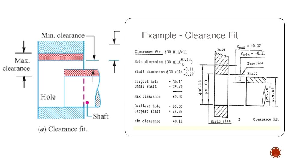
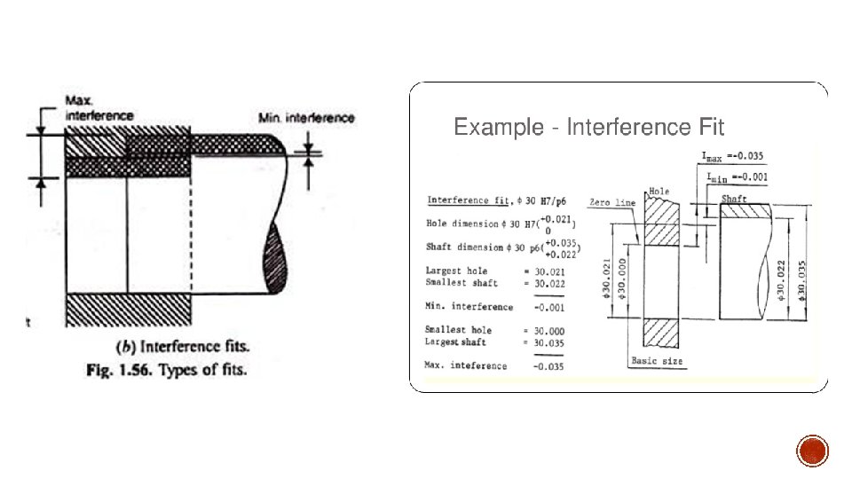
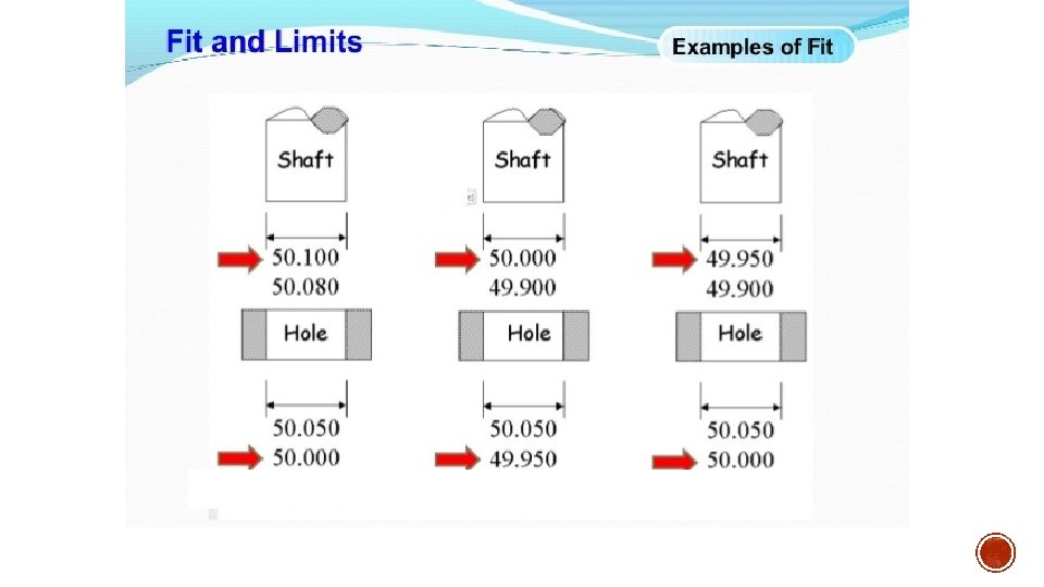
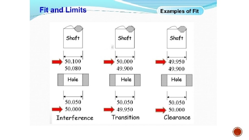
The term fits refers to the degree of tightness or looseness between two mating parts. Depending upon the actual limits of the hole and shaft. Fits may be classified into the following three types: (i) Clearance fit. (ii) Interference fit. (iii) Transition fit.
Clearance: § The term clearance refers to the difference between the sizes of the hole and the shaft before assembly. Clearance must be positive. Interference: § The term interference refers to the arithmetical difference between the sizes of the- hole and the shaft, before assembly. Interference is negative clearance.
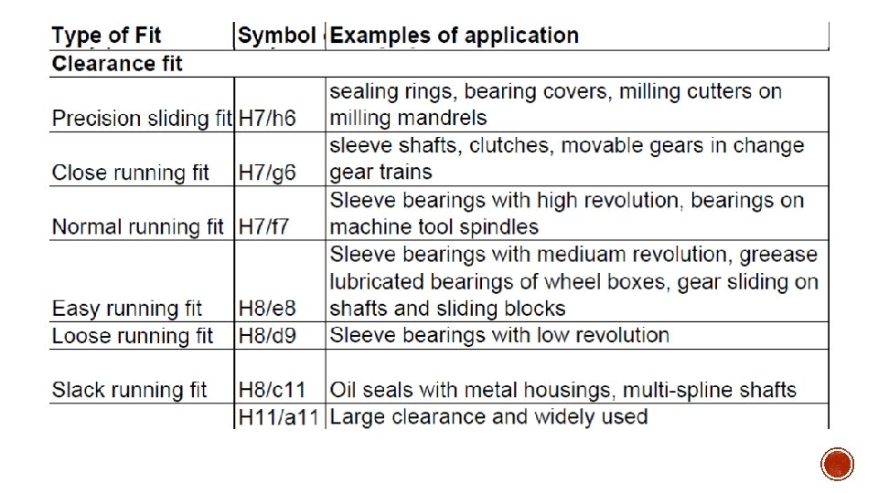
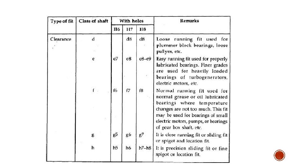
§ A fit that always provides a clearance (gap) between the hole and shaft when assembled is known as clearance fit. § In clearance fit, the minimum size of the hole is either greater than or, equal to (in extreme case) the maximum size of the shaft, so that the shaft can rotate or slide as per the purpose of the assembled members. § In clearance fit, the difference between the maximum size of the hole and minimum size of the shaft is called maximum clearance, whereas the minimum size of the hole and maximum size of the shaft is known as minimum clearance. § The clearance fit may be of different types, e. g. , slide fit, easy sliding fit, running fit, slack running fit and loose running fit, etc.
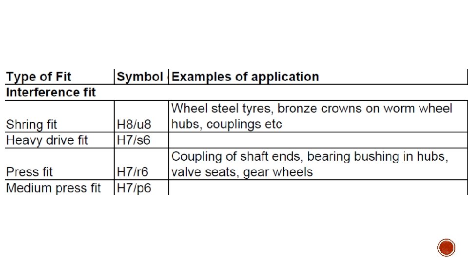
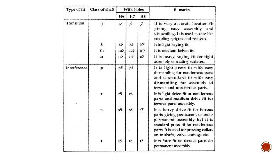
§ A fit that everywhere provides interference between the hole and shaft when assembled, is known as interference fit. In interference fit, the maximum size of the hole is either smaller or equal to (in extreme case) the minimum size of the shaft. § In this fit, the shaft and the hole members are intended to be attached permanently, so that they can be used as a solid component, but according to the purpose and function of this combination, this type of fit can be varied. § It may be noted from the figure that in interference fit, the tolerance zone of the hole is entirely below the tolerance zone of the shaft. § In interference fit, the difference between the minimum size of the hole and the maximum size of the shaft is called maximum interference. Whereas difference between the maximum size of the hole and the minimum size of the shaft is known as minimum interference, Interference fit is shown in Fig. 1. 56 (b). § The interference fit may be of different types, e. g. , shrink fit, light drive fit, heavy drive fit. Example of this type of fit are bearing bushes which are in an interference fit in their housing of a small end of the connecting rod of an engine.
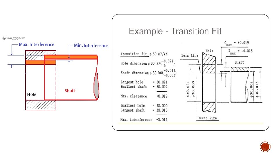
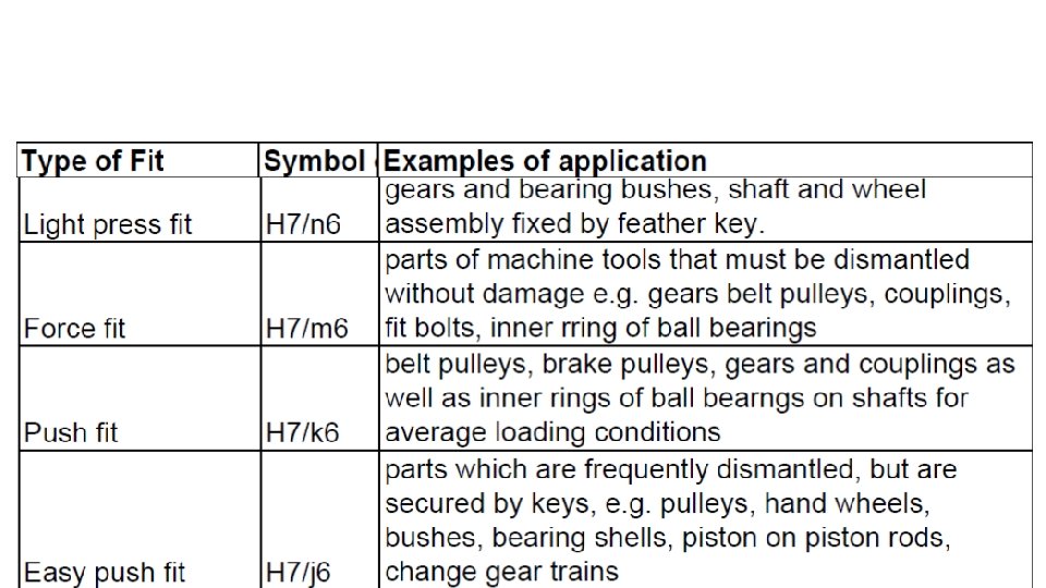
§ A fit which may provide either a clearance or interference between the shaft and hole when assembled, depending on the actual sizes of the shaft and hole, is known as Transition fit. It may be noted that in a transition fit, the tolerance zone of shaft and hole overlap completely or partially. § The transition fit may be of different types, e. g. Push fit, force fit, tight fit etc.
§ In hole basis system, the size of the hole is constant and different fits are obtained by varying the size of shaft as shown in Fig. 1. 57 (a). § It may be noted that, from manufacturing point of view, a hole basis system is always preferred. Because holes are produced by standard size of drills and reamers, whose size cannot be adjusted easily on the other hand, the size of the shaft which is to go into hole, can be easily adjusted by turning and grinding.
§ In shaft basic system, the size of the shaft is constant and different fits are obtained by varying the size of the hole, as shown in fig. 1. 58 (b).
§ The shaft shown in Fig. 1. 59 has an upper and lower limit of 40. 05 mm and 39. 95 mm respectively. The shaft is said to have a maximum metal limit (MML) of 40. 05 mm because at this limit the shaft has the maximum possible amount of metal. § The limit of 39. 95 mm is called the minimum or least metal limit (LML) because at this limit the shaft has minimum or least possible amount of metal. §
§ The hole shown in figure 1. 60 has an upper and lower limit of 20. 05 mm and 19. 95 mm respectively. When the hole is at its upper limit the minimum amount of metal is left. § The limit of 20. 05 mm is therefore called the least or minimum metal limit (LML). When the hole is at its lower limit the maximum amount of metal is left and hence the limit of 19. 95 mm is called the maximum metal limit (MML).
§ If you leave a dimension without a tolerance, no one else will know the importance, or the un importance, of that dimension. § Not only can a lack of tolerances lead to improper fits, it will also add to delays and higher costs. § When used correctly, you have much to gain when using tolerances. Parts with proper tolerances will fit as desired, be it a sliding fit, or a press fit.
§ When applying GD&T the first consideration is to establish a datum reference frame based on the function of the part in the assembly with its mating parts. After the datum reference frame is established, the form of the primary datum feature is controlled, followed by the location of the secondary and tertiary datum features. After the datum features are related relative to each other, the remaining features are controlled for orientation and location relative to the datum reference framework.
Why datum is used in GD & T? § Coordinate systems are valuable because they're used to locate objects. In GD&T they are used to orient and locate tolerance zones. Every Datum exists within the context of some Datum Reference Frame. Why are datum targets used? § In GD&T, a datum target may be used to specify a point, line, or area on a part to establish a datum. This is sometimes necessary when a part feature is too large or naturally irregular to create a datum. Parts that are cast, forged, or molded often benefit from the use of datum targets.
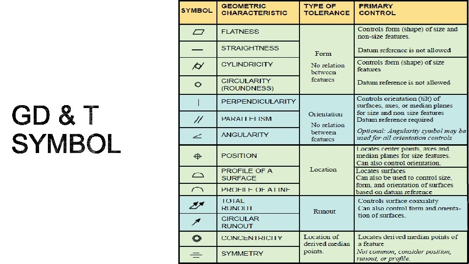
§ A datum feature is usually an important functional feature that needs to be controlled during measurement as well. § All GD&T symbols except for the form tolerances (straightness, flatness, circularity and Cylindericity) can use datum to help specify what geometrical control is needed on the part. § All datum features must be identified with datum feature symbols and specified in feature control frames.
§ Datum features may be designated with any letter of the alphabet except I, O, and Q. The datum feature symbol is used to identify physical features of a part as datum features. § Datum feature symbols must not be applied to centerlines, center planes, or axes.
§ Cylindrical Datum Features 1
What are all the measurement to be check in this table? 1. 2. 3. 4. 5. 6. Length Width Height Thickness Flatness Straightness
What are all the measurement to be check in this table? 1. 2. 3. 4. 5. 6. Length Width Height Thickness Flatness Straightness
What are all the measurement to be check in this component? 1. 2. 3. 4. Diameter Height Thickness Cylindericity
What are all the measurement to be check in this component? 1. Diameter 2. Height 3. Circularity
What are all the measurement to be check in this component? 1. Length 2. diameter 3. Parallelism
What are all the measurement to be check in this component? 1. 2. 3. 4. 5. Length Width Height Thickness Perpendicularit y
What are all the measurement to be check in this component? 1. Length 2. diameter 3. Parallelism
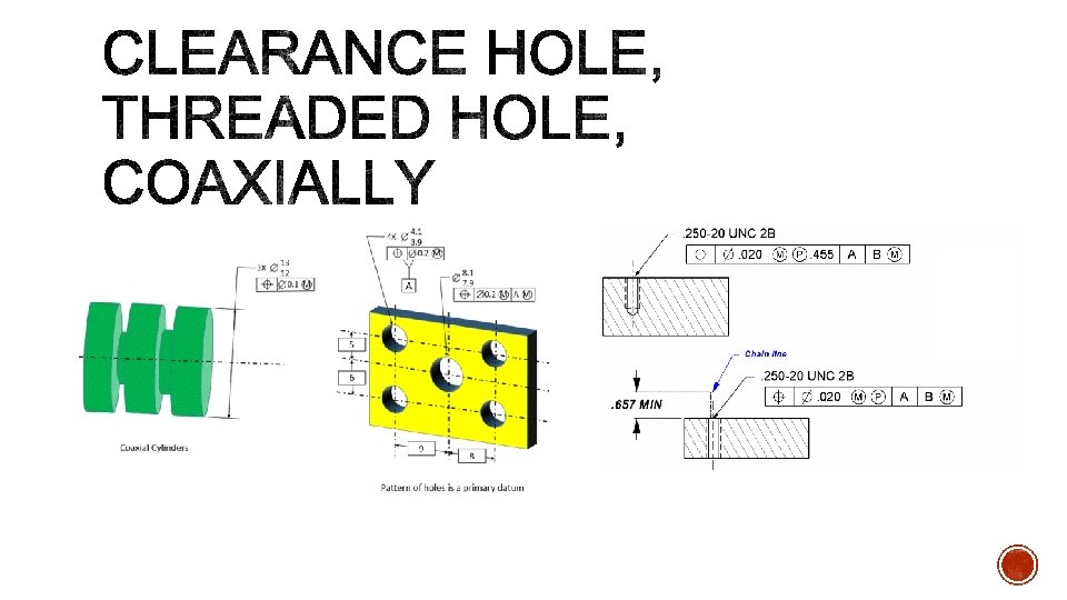
What are all the measurement to be check in this component? 1. 2. 3. 4. 5. Diameter Thickness Length Width Position
What are all the measurement to be check in this component? 1. Concentricity
What are all the measurement to be check in this component? 1. Symmetry