Tolerancing n n Definition Allowance for specific variation
- Slides: 25
Tolerancing n n Definition: Allowance for specific variation in the size and geometry of a part Need for Tolerancing ¨ It is IMPOSSIBLE to manufacture a part to an EXACT size or geometry ¨ Since variation from the drawing is inevitable we must specify the acceptable degree of variation ¨ Large variation may affect part functionality ¨ Small allowed variation affects the part cost n n requires precise manufacturing may result in incorrect rejection of otherwise functional parts
Tolerance Follows Function n Assemblies: ¨ n Interchangeable Parts: ¨ n Parts will not fit together if their dimensions do not fall with in a certain range of values If a replacement part is used it must duplicate the original part within certain limits of deviation The relationship between functionality and size/shape of an object varies with the part Automobile transmission is very sensitive to the size & shape of the gears ¨ Bicycle is not as sensitive to the size & shape of the gears ¨
Two Forms of Physical Tolerance n n Size ¨ Limits specifying the allowed variation in each dimension (length, width, height, diameter, etc. ) are given on the drawing Geometry ¨ Geometric Dimensioning & Tolerancing (GD&T) n Allows for specification of tolerance for the geometry of a part separate from its size n GD&T uses special symbols to control different geometric features of a part
Tolerance Spec Hierarchy n Generally Three Levels of Tolerances ¨ DEFAULT: Placed in the Drawing Title-Block by The Engineering Firm n Typically Conforms to Routine Tolerance Levels ¨ GENERAL: Placed on the Drawing By the Design. Engineer as a NOTE n Applies to the Entire Drawing n Supercedes the DEFAULT Tolerance ¨ SPECIFIC: Associated with a SINGLE Dimension or Geometric Feature
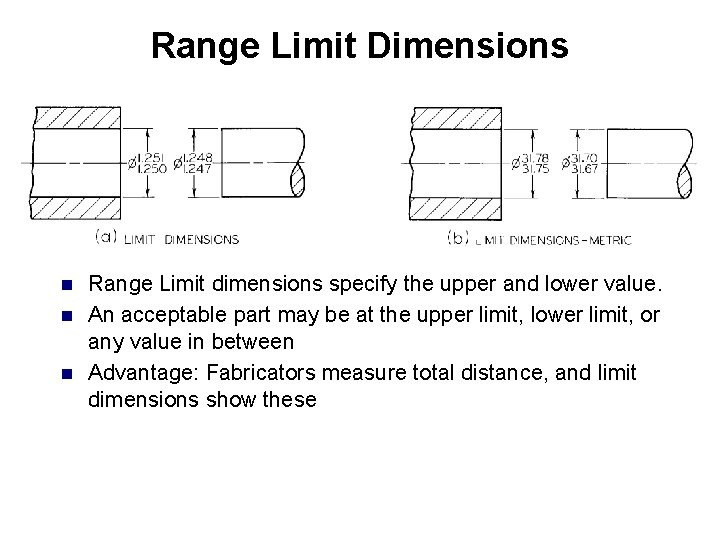
Range Limit Dimensions n n n Range Limit dimensions specify the upper and lower value. An acceptable part may be at the upper limit, lower limit, or any value in between Advantage: Fabricators measure total distance, and limit dimensions show these
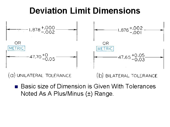
Deviation Limit Dimensions n Basic size of Dimension is Given With Tolerances Noted As A Plus/Minus (±) Range.
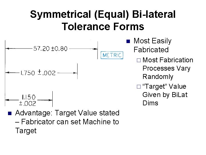
Symmetrical (Equal) Bi-lateral Tolerance Forms n Most Easily Fabricated ¨ Most Fabrication Processes Vary Randomly ¨ “Target” Value Given by Bi. Lat Dims n Advantage: Target Value stated – Fabricator can set Machine to Target
Geometric Dimensioning & Tolerancing n n Uses Standard Symbols To Indicate Tolerances That Are Based On The Feature’s Geometry. Sometimes Called Feature-Based Dimensioning & Tolerancing, Or True Position Dimensioning & Tolerancing Uses “Feature Control Frames” To Indicate Tolerance(s) “State of the Art” for Tolerances
History of Tolerancing n n In the 1800’s, manufacturing used the “cut & try, file & fit” approach. The plus-minus (or coordinate) system of tolerancing was next developed. In the 1900’s, the first GD&T standards came out to improve the quality & utility of engineering drawings. In 1966, the united GD&T standard was published
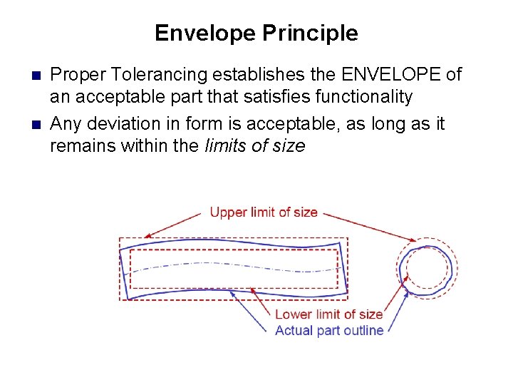
Envelope Principle n n Proper Tolerancing establishes the ENVELOPE of an acceptable part that satisfies functionality Any deviation in form is acceptable, as long as it remains within the limits of size
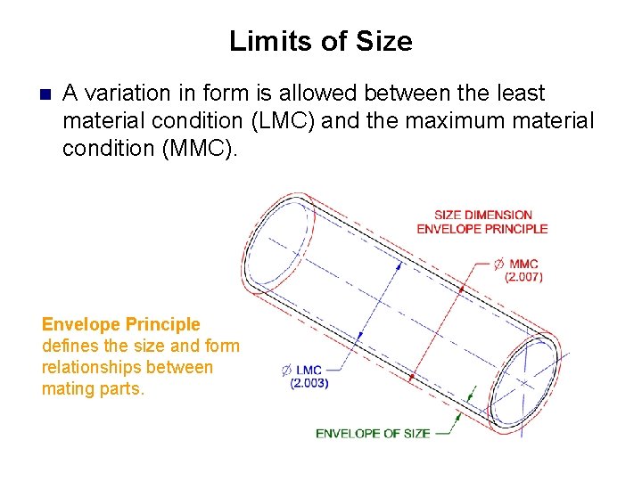
Limits of Size n A variation in form is allowed between the least material condition (LMC) and the maximum material condition (MMC). Envelope Principle defines the size and form relationships between mating parts.
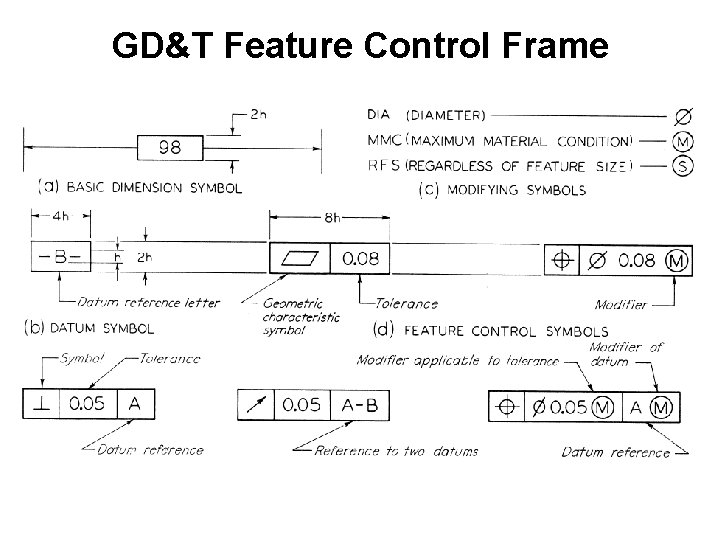
GD&T Feature Control Frame
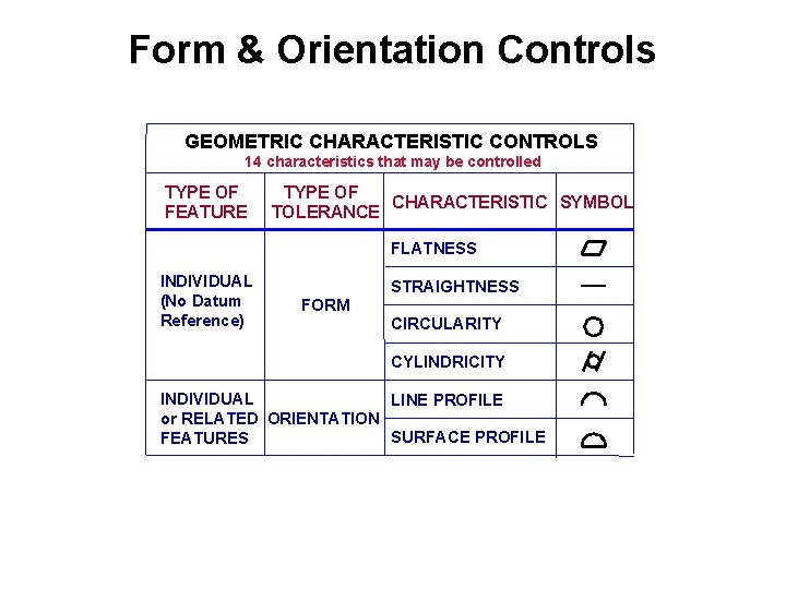
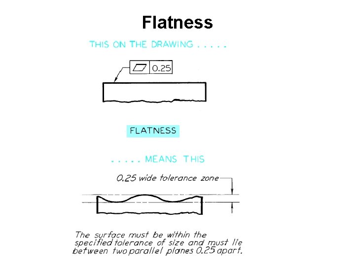
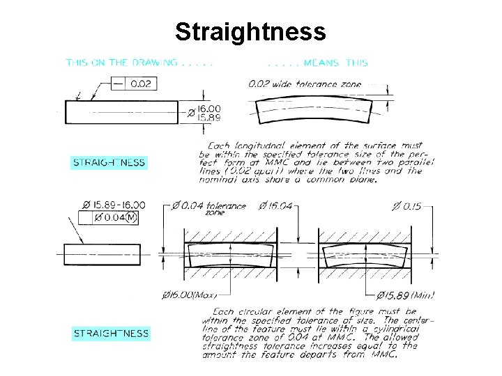
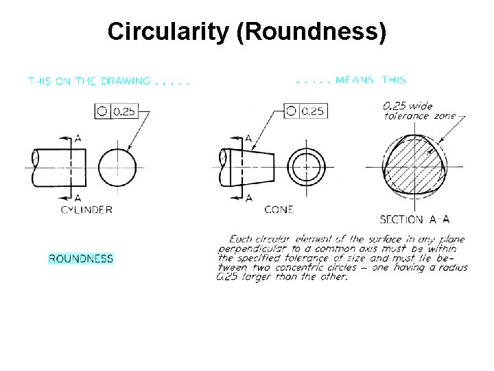
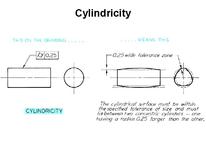
Form & Orientation Controls GEOMETRIC CHARACTERISTIC CONTROLS 14 characteristics that may be controlled TYPE OF FEATURE TYPE OF CHARACTERISTIC SYMBOL TOLERANCE FLATNESS INDIVIDUAL (No Datum Reference) STRAIGHTNESS FORM CIRCULARITY CYLINDRICITY INDIVIDUAL LINE PROFILE or RELATED ORIENTATION SURFACE PROFILE FEATURES
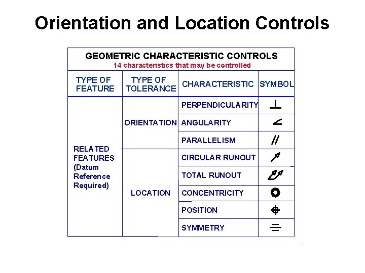
Orientation and Location Controls GEOMETRIC CHARACTERISTIC CONTROLS 14 characteristics that may be controlled TYPE OF FEATURE TYPE OF CHARACTERISTIC SYMBOL TOLERANCE PERPENDICULARITY ORIENTATION ANGULARITY PARALLELISM RELATED FEATURES (Datum Reference Required) CIRCULAR RUNOUT TOTAL RUNOUT LOCATION CONCENTRICITY POSITION SYMMETRY
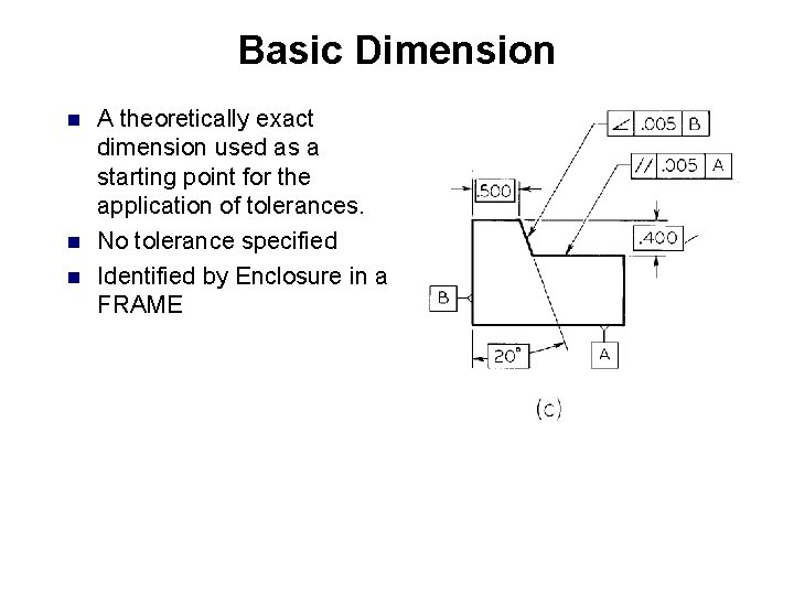
Basic Dimension n A theoretically exact dimension used as a starting point for the application of tolerances. No tolerance specified Identified by Enclosure in a FRAME
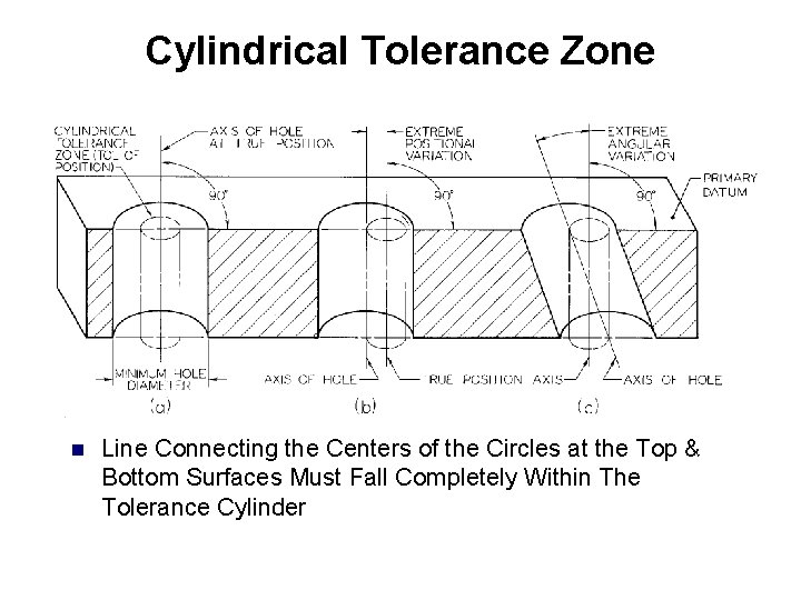
Cylindrical Tolerance Zone n Line Connecting the Centers of the Circles at the Top & Bottom Surfaces Must Fall Completely Within The Tolerance Cylinder
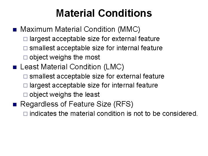
Material Conditions n Maximum Material Condition (MMC) ¨ largest acceptable size for external feature ¨ smallest acceptable size for internal feature ¨ object weighs the most n Least Material Condition (LMC) ¨ smallest acceptable size for external feature ¨ largest acceptable size for internal feature ¨ object weighs the least n Regardless of Feature Size (RFS) ¨ indicates the material condition is not to be considered.
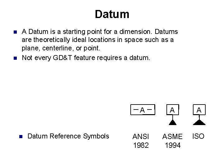
Datum n n A Datum is a starting point for a dimension. Datums are theoretically ideal locations in space such as a plane, centerline, or point. Not every GD&T feature requires a datum. n Datum Reference Symbols A ANSI 1982 ASME 1994 ISO
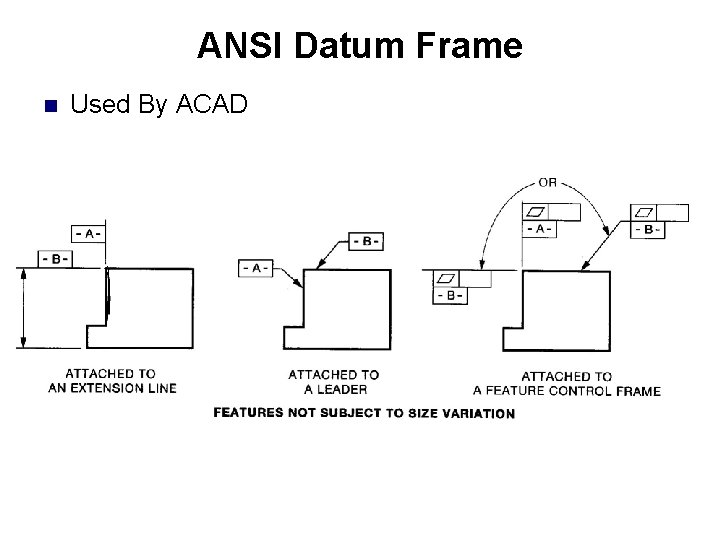
ANSI Datum Frame n Used By ACAD
Flatness
Straightness
Circularity (Roundness)
Cylindricity
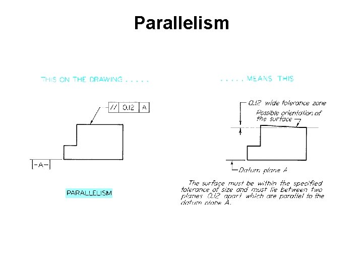
Parallelism
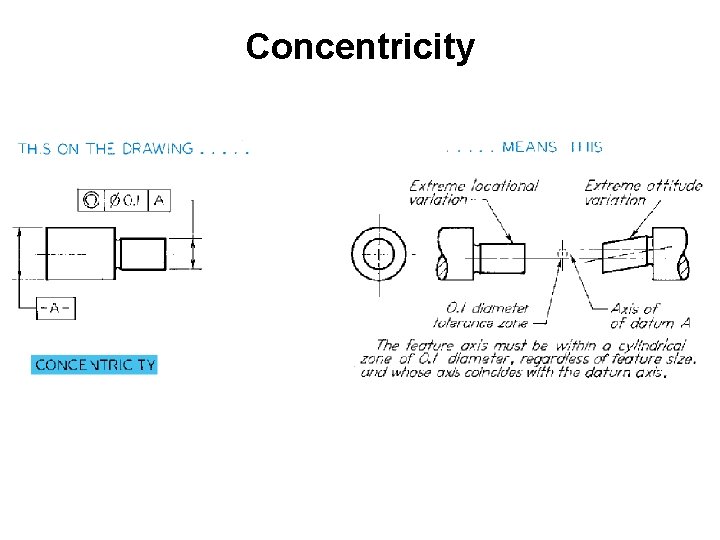
Concentricity