LIMITS FITS AND TOLERANCE BY PROF KHAN AAMIR

LIMITS, FITS AND TOLERANCE BY PROF. KHAN AAMIR

TERMINOLOGY

ØBASIC SIZE: It is the standard size of a part , with reference to which all the limits of variations of size are determined. ØZERO LINE: the line corresponding to basic size is called as zero line. ØSHAFT AND HOLE: These terms are used to designate all the external and internal features of any shape and not necessarily cylindrical. ØHOLE DESIGNATION: By upper case letters from A, B, . . . Z, Za, Zb, Zc (excluding I, L, O, Q, W and adding Js, Za, Zb, Zc) - 25 nos. Indian Stds. ØSHAFT DESIGNATION: By lower case letters from a, b, . . . z, za, zb, zc (excluding i, l, o, q, w and adding js, za, zb, zc) - 25 nos.

DEVIATION ØUPPER DEVIATION: The algebraic difference between the maximum limit of size (of either hole or shaft) and the corresponding basic size ØLOWER DEVIATION: The algebraic difference between the minimum limit of size (of either hole or shaft) and the corresponding basic size ØFUNDAMENTAL DEVIATION: It is one of the two deviations which is chosen to define the position of the tolerance zone

Tolerance: The algebraic difference between upper and lower deviations. It is an absolute value.

Types of tolerance • Unilateral tolerance : if the tolerance is allowed on one side of the basic size, the system of tolerance is said to be unilateral.

• Bilateral tolerance : if the tolerance is allowed on both side of the basic size, the system of tolerance is said to be unilateral.

LIMITS The limits are two extreme permissible sizes of a part between which, the actual size of that part is contained. They are fixed with reference to the basic size of that dimension.

Ø Basic shaft: it is the shaft, whose upper deviation is zero or whose max. limit of size is equal to basic size. Ø Basic hole: it is the hole, whose lower deviation is zero or whose min. limit of size is equal to basic size.

Allowance Ø Allowance is the prescribed difference between the hole dimension and shaft dimension for any type of fit. Ø It is the intentional difference between the lower limit of the hole and higher limit of the shaft.

Fits Ø The relation between the two parts, where one is inserted into the other with a certain degree of tightness or looseness is known as fit. Ø Fit is the degree of tightness or looseness between two mating parts to perform a definite function. Ø fit is the relation between dimensions of two mating parts before their assembly. Ø Classification of fits

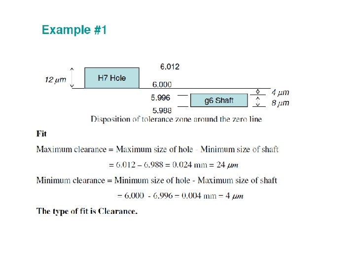
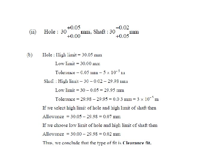
Clearance fit In this type of fit, the largest permitted shaft diameter is smaller than the Diameter of the smallest hole, so that, the shaft can rotate or slide through, with Different degrees of freedom according to the purpose of the mating members

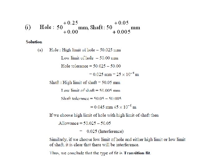
Transition fit • In a fit of this type, the diameter of the largest allowable hole is greater than that of the smallest shaft, but the smallest hole is smaller than the largest shaft, so that, small positive or negative allowance between the shaft and hole members are employable. • In this type of fit, the size limits of mating (shaft and hole) parts are so selected that, either clearance or interference may occur depending upon the actual size of the parts.

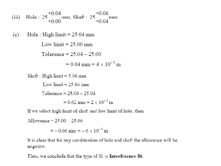
Interference fit Ø In this type of fit, diameter of minimum allowable shaft is greater than that of Maximum allowable hole. Ø In this type of fit, the sizes of the mating parts are so selected that, interference Or negative allowance will always occur.

Hole Basis System • In this system, the design size of hole, whose lower deviation (fundamental deviation) is zero, is assumed as basic size and different class of fits are obtained by varying the limits of the shaft only. • In other words, the limits of the hole are kept constant and those of the shaft are varied so as to obtain the necessary fit.

Shaft Basis System • In this system, the design size of a shaft, whose upper deviation (fundamental deviation) is zero, is assumed as basic size and different class of fits obtained by varying the limits of the hole only. • In other words, the limits of shaft are kept constant and limits of holes are varied to obtain the necessary type of fit.

Designation of fit Ø To describe completely a hole or a shaft, its basic size followed by appropriate letter and the number of tolerance grade is given. Ø Holes are designated by capita letter Ø Shafts are designated by small letter. Example, Ø 20 mm hole ‘H' with tolerance grade IT 7 is designated as 20 H 7. Ø 20. mm 'f' shaft with tolerance grade IT 8 is designated as 20 f 8. for shafts a to h -clearance fit, j to n - transition it, p to z -interference fit.

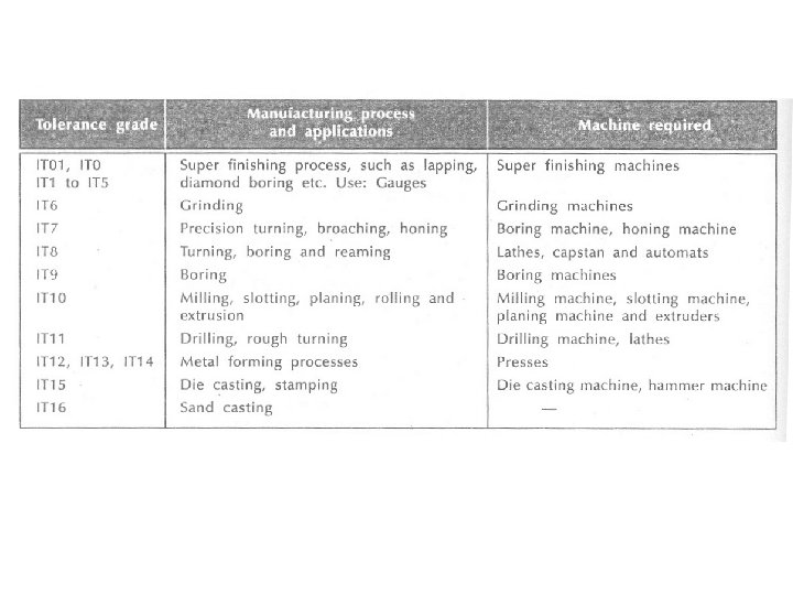
Grades of Tolerance Grade of Tolerance: It is an indication of the level of accuracy. There are 18 grades of tolerances – IT 01, IT 0, IT 1 to IT 16 IT 01 to IT 4 - For production of gauges, plug gauges, measuring instruments IT 5 to IT 7 - For fits in precision engineering applications IT 8 to IT 11 – For General Engineering IT 12 to IT 14 -For Sheet metal working or press working 14 IT 12 to IT 14 –For Sheet metal working or press working IT 15 to IT 16 – For processes like casting, general cutting work

Designation of fits example: Ø 50 H 7 g 7 : is a fit indicated by its basic size 50 mm, followed by symbols representing the limits of hole (H 7 i. e hole having basic size 50 mm and tolerance grade IT 7) and shaft (g 7 i. e shaft having basic size 50 mm and tolerance grade IT 7) the type of fit system is hole basis and obtained type of fit is clearance fit. Ø 35 H 8 j 7 :
- Slides: 27