LINEAR MEASUREMENT INTRODUCTION v Measurement of horizontal distance


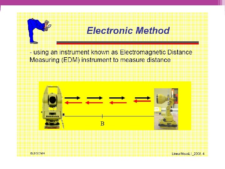
 Electronic distance")


 • When a steel tape is pulled with a tension")
 Cp = Pull Correction P 0 = standard pull P")


 distance")


1/2 BC 1")


 Equipment")

- Slides: 63
LINEAR MEASUREMENT
INTRODUCTION v Measurement of horizontal distance has taken a variety of forms with marked variations in the accuracies achieved. v It is very important to know the methods available and their accuracies to obtain the required precision with economy
Mechanical Methods of determining distance Electronic Optical
Mechanical Method
Optical Method
METHOD OF LINEAR MEASUREMENT • • Pacing Odometer Tapes Chains Tacheometry (stadia) Electronic distance measurement (EDM) Satellite systems and others.
TAPING • Taping is used for short distances and the length generally 10 m, 30 m, 50 m, and 100 m. • Linen or glass fibre tapes used for general use, where precision is not a prime consideration. • For more precise version, tapes are made of steel is preferred. • For high accuracy work, steel bands mounted in an open frame are used.
TAPING EQUIPMENT RANGE POLE TAPING PINS TAPES PLUMB BOBS
TAPING • Taping must always be STRAIGHT • Tape must not be twisted • Use CHAINING ARROWS for intermediate points • Tape horizontally if possible • Tape on the ground if possible • Slope taping needs to be reduced
TAPING PROCEDURES • • Site inspection and setup Lining in Applying tension Plumbing Marking tape length Reading the tape Recording the distance
SITE INSPECTION AND SETUP • A preliminary investigation is to identify and locate initial starting and fixed points and to map out the measurements strategy. • Range poles may be placed to help define the measurement line. • Field notes should be taken for later reference (e. g. date, weather, temperature, potential obstructions, topography etc. )
LINING IN • Using range poles, line measured should be marked at both ends and at intermediate points where necessary (to ensured unobstructed sight lines). • Required at least 2 person (forward and rear tape person). The rear tape person holds the tape roll at the starting point; while the forward tape person pulls the tape to the end point of required distance or until the entire tape length has been deployed. • The rear and forward tape person should always remain within sight of each other. If the sight line is obstructed, it is necessary to “break” the measurement distance into shorter lengths to bypass the obstruction.
APPLYING TENSION • The rear tape person should holding 100 -ft end of a tape over the first (rear) point lines in while the forward tape person holding the zero end of the tape. • For an accurate results, the tape must be straight and the two ends held at the same elevation. Tension apply generally between 10 and 25 lb.
PLUMBING • Weeds, brush, obstacles and surface irregularities may make it undesirable to lay a tape on the ground. • Thus, the tape is held above ground level in horizontal position. • Each end point of a measurement is marked by placing the plumb-bob string over the tape and securing it with one thumb. • A plumb-bob is used to locate the measurement point on the tape vertically above a fixed marker, or to place taping pins to mark tape lengths
MARKING TAPE LENGTHS • When line in properly, tension has been applied and the rear tape person is over the point stick is called out. • The forward tape person then places a pin exactly opposite the zero mark of the tape and calls stuck.
READING THE TAPE • There are two commons styles of graduation on 100 -ft surveyor ‘s tapes. ▫ Common type of tape has a total graduated length of 101 ft. ▫ Another type in practice has total graduated length of 100 ft
RECORDING THE DISTANCE • Accurate field work may be spoiled by careless recording. • Although taping procedure may appear to be relatively simple, high precision is difficult to achieve especially for beginners. • Taping is a skill that can be best taught and learned by field demonstration and practice.
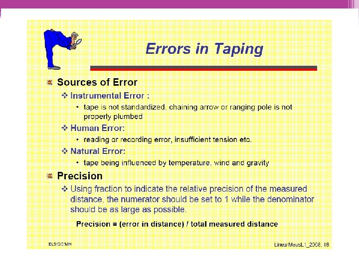
INCORRECT LENGTH OF TAPE • Incorrect length of tape can be one of the most important errors. • The tape is not of ‘true’ length. • Error caused by incorrect tape length occurs each time the tape is used.
CORRECTION FOR STANDARD LENGTH • Actual length compared to standard tape of known length. • Correction to be made if the actual tape length is not equal to the standard value. Ca = LC/l Where: Ca = correction for absolute length C = Correction to be applied to the tape L = Measured length of the line l = Nominal length of the tape
CORRECTION FOR TEMPERATURE • Error caused by temperature change may be practically eliminate by either ▫ Measure temperature and making correction ▫ Using Invar tape (Nickel-steel alloy tapes) *usually used primarily in high precision taping.
CORRECTION FOR TEMPERATURE Where: CT = Temperature correction Tm = temperature during measurement T 0 = Temperature of standardisation � = Coefficient of thermal expansion of materi 0. 0000035/o. C for steel, 0. 000000122/o. C for invar. L = measured length
CORRECTION FOR TENSION (PULL) • When a steel tape is pulled with a tension greater than its standard pull, the tape will stretch and become longer than its standard length.
CORRECTION FOR TENSION (PULL) Cp = Pull Correction P 0 = standard pull P = pull applied during measurement A = Area of cross section of the tape (in cm 2) E = Modulus of elasticity of tape, 2. 1 x 10⁵ N/mm 2 for steel, 1. 54 x 105 N/mm 2 for invar L = Measured length
EXAMPLE 1 A line was measured with a steel tape which was exactly 30 m at a temperature of 20°C and a pull of 10 kg. The measured length was 1650 m. The temperature during measurement was 30°C and the pull applied was 15 kg. Find the true length of the line, if the cross sectional area of the tape was 0. 025 cm 2. The coefficient of expansion of the material of the tape per °C is 3. 5 x 10 -6 and modulus of elasticity of the material of tape is 2. 1 x 10⁶ kg/cm 2.
CORRECTION FOR SLOPE • In taping on uneven or sloping ground, it is standard practice to hold the tape horizontally and use a plumbob. • Wind exaggerates this problem and may make accurate work imposibble. • On steeper slope, where the length cannot be held horizontally without plumbing from above shoulder level, shorter distances are measured and accumulated to total.
S 1 A S 2 AB= S 1+S 2+S 3 required (horizontal) distance
h = different in elevation L = measured length of the line
Example 2 The downhill end of a 30 m tape is held 90 cm too low. What is the horizontal distance measured?
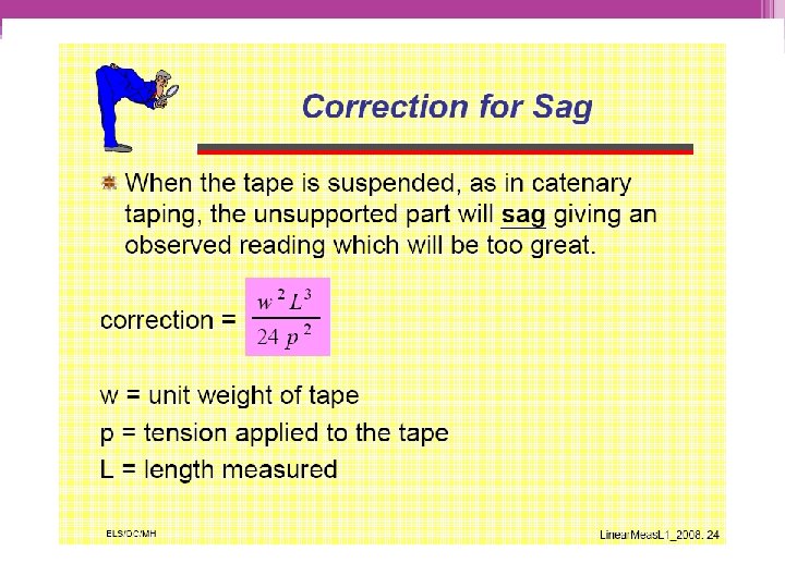
CORRECTION FOR SAG • Because of sag, the horizontal distance is less than the graduated distance between tape ends. • Can be reduced by applying greater tension but not eliminated unless the tape is supported throughout. • Eliminated by ▫ Supporting the tape at short intervals or throughout ▫ Computing the sag correction
CATENARY TAPING mea sure nce d dista required distance measured distance required distance
TAPE MUST BE STRAIGHT ce n ista d obstruction req e uir ce n a st i d d ured s a me measured distance required distance
Example 3 A 100 m tape is suspended between the ends under a pull of 200 N. The weight of tape is 30 N. Find the correct distance between the tape ends.
CHAINS • Prepared with 100 or 150 pieces of galvanised mild steel using wire of diameter 4 mm. • The ends of the each pieces are bent to form loops. Then its connected together with the three oval rings which make the chain flexible. • Tallies are provided at every 10 or 25 links for facility of counting. 'One link' means the distance between the centres of adjacent middle rings.
TYPES OF CHAINS • • • Metric chain Steel band Engineers chain Gunter' s chain Revenue chain
METRIC CHAINS • Available in lengths of 20 m and 30 m. • The 20 m chain is divided into 100 links, each of 0. 2 m. • Tallies are provided at every 10 links (2 m). This chain is suitable for measuring distances along fairly level ground.
STEEL BAND • It consists of a ribbon of steel of width 16 mm and of length 20 or 30 m. • It has a brass handle at each end. • The steel band is uses in projects where more accuracy is required.
ENGINEERS CHAIN • Prepared in 100 ft long and is divided into 100 links. • Each link is I ft. Tallies are provided at every 10 links (10 ft). • The central tally being round.
GUNTERS' CHAIN • It is 66 ft long and divided into 100 links. So, each link is of 0. 66 ft. • It was previously used for measuring distances in miles.
REVENUE CHAIN • The revenue chain is 33 ft long and divided into 16 links. • It is mainly used in - cadastral survey.
RANGING • The process of establishing the intermediate points on a straight line between two end points. • Ranging must be done before a survey line is chained. • Ranging may be done: by direct observation by the naked eye or by line ranger or by theodolite. Generally, ranging is done by the naked eye with the help of three ranging rods. • Ranging may be of two kinds: ▫ Direct ▫ Indirect or reciprocal
DIRECT RANGING • When intermediate ranging rods are fixed on a straight line by direct observation from end stations. • Direct ranging is possible when the end stations are intervisible.
CONT… • A and B are two end stations of a chain line. Suppose it is required to fix a ranging rod at the intermediate point P on the chain line, so the points A, P and B become straight line. The surveyor stands about 2 m behind the ranging rod at A by looking towards the line AB. • The assistant holds a ranging rod at P vertically at arm 's length. The rod should be held lightly by the thumb and forefinger. Now, the surveyor directs the assistant to move the ranging rod to the left or right until the three ranging rods come exactly in the same straight line. • To check the non-verticality of the rods. the surveyor bends down and looks through the bottom of the rods. The ranging will be perfect, when the three ranging rods coincide and appear as a single rod. When the surveyor is satisfied that the ranging is perfect.
INDIRECT OR RECIPROCAL RANGING • When the end stations are not intervisible due to rising ground between them, or due to long distance between the ends, indirect ranging is done. • This method is known, as indirect ranging or reciprocal ranging. The following procedure is adopted for indirect ranging.
ADJUSTMENT OF CHAIN Chains are adjusted in the following ways: • When the chain is too long, it is adjusted by : ▫ ▫ Closing up the joints of the rings , Hammering the elongated rings, Replacing some old rings by new rings, and Removing some of the rings. • When the chain is too short , it is adjusted by : ▫ ▫ Straightening the bent links, Opening the joints of the rings, Replacing the old rings by some larger rings, and Inserting new rings where necessary.
ADVANTAGES AND DISADVANTAGES • Chains have the following advantages: -They can be read easily and quickly. -They can withstand wear and tear. -They can be easily repaired or rectified in the field. • They have the following disadvantages: -They are heavy and take too much time to open or fold. -They become longer or shorter due to continuous use. -When the measurement is taken in suspension, the chain sags excessively.
METHOD OF CHAINING ON SLOPING GROUND • Chaining along a sloping ground, the horizontal distances between two stations are measured carefully. The following are the different methods that are generally employed: ▫ Direct method or stepping method, and ▫ Indirect method.
DIRECT METHOD • This method is applied when the slope of the ground is very steep. In this method, the sloping ground is divided into a number of horizontal and vertical strips, like steps. • So, this method is known as the stepping method. • The lengths of horizontal portions are measured and added to get the total horizontal distance between the points. The steps may not be uniform, and would depend on the nature of the ground.
INDIRECT METHOD • When the slope of the ground surface is long, the stepping method is not suitable. In such a case, the horizontal distance may be obtained by the following processes: ▫ By measuring the slope with a clinometer, ▫ By applying hypotenusal allowance, and ▫ By knowing the difference of level between the points.
APPLYING HYPOTENUSAL ALLOWANCE • Horizontal distance p. Q maybe found by applying hypotenusal allowance. Ɵ = Angle of slope of the ground p. Q = p 1 Q = 1 chain length PQ = chain length x sec Ɵ Pp 1 = Hypotenusal allowance = chain length x (sec Ɵ – 1)
EXAMPLE 1 • While measuring the distance on a slope it was found that the ground rises by 3. 2 m for each 20 m chain length. Find the angle of slope and the hypotenusal allowance per chain length.
KNOWING THE DIFFERENCE OF LEVEL • A, B, C and D are different point, on sloping ground. The difference of level between these points is determined by a levelling instrument.
CONT… Required horizontal distance AB 1 = (l 12 – h 12)1/2 BC 1 = (l 22 – h 22)1/2 CD 1 = (l 32 – h 32)1/2
OBSTACLE IN CHAINING • When chaining is free, but vision is obstructed • When chaining is obstructed , but vision is free • When chaining and vision are both obstructed.
When chaining is free, but vision is obstructed P C 1 A D 1 E 1 B JUNGLE C D E
When chaining is obstructed , but vision is free E F POND A C D Horizontal distance CD = EF B
When chaining is obstructed , but vision is free E POND A C D Horizontal distance CD = (ED 2 – CE 2)1/2 B
When chaining and vision are both obstructed. A C 1 D 1 E 1 F 1 C D E F Horizontal distance E 1 E = F 1 F = D 1 D = C 1 C DE = D 1 E 1 B
CONCLUSION OF LINEAR MEASUREMENT • • • Equipment is fairly cheap (except EDM) Equipment is easy to maintain and adjust. Distances are easy to measure Very accurate results can be achieved Measurement line needs to unobstructed Errors occur and need to be managed or minimized
THANK YOU Edited from original slide by Mdm. Liyana