Chapter Five Flow Measurement INTRODUCTION Fluid measurements include


- Slides: 22
Chapter Five Flow Measurement
INTRODUCTION � � Fluid measurements include the determination of pressure, velocity, discharge, shock waves, density gradients, turbulence, and viscosity. Many ways used for measuring like Direct measurements for discharge consist in the determination of the volume or weight of fluid that passes a section in a given time interval. Indirect methods of discharge measurement require the determination of head, difference in pressure, or velocity at several points in a cross section, and with these the computing of discharge
OBJECT � At the end of this chapter the student should be able to: � Describe the importance of flow sensing and its problem � Describe the principle of operation of different flow meter � Describe the constructional and mean aspects of differential meter.
WHY IT IS IMPORTANT? � Flow measuring are needed for flow control and flow measuring � Flow control are needed for controlling � Temperature � Pressure � Level tank
TYPES OF FLOW MEASURING � � � The flow measurements can be classified into: Obstructive Device Differential pressure flow meter like: Venture, orifice, pitot tube Rotameter Turbines Non-obstructive Electormegnatic Ultrasonic Cross-correlation
DIFFERENTIAL PRESSURE FLOW METER � Its widely used to measure the liquid and gas � The principle is that a restriction is placed in the pipe and the differential pressure developed across the restriction is measured � The differential pressure output is calibrated in terms of volumetric flow rate (not mass this will need density)
1 - ORIFICE METER � The primary element of an orifice meter is simply a flat plate containing a drilled (hole) located in a pipe perpendicular to the direction of fluid flow
Or
2 - VENTURI METER Or
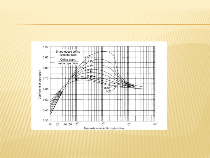
� These equations for venture and orifice are valid for � Turbulent flow � Incompressible flow � For gases : additional expansibility factor � The values of discharge coeffiecient depends on � Type of flow measurement; venture and orifice � Diameter ratio � Reynold number
CHARACTERISTICS OF DIFFERENTIAL PRESSURE MEASUREMENT � No moving parts, cheap, maintainable � Well established, calibration available � Permanent head loss � Nonlinear relationship, so its not use for low pressure since the pressure has square root with velocity � Discharge coefficient changes with wear, flow distribution � Generally applicable for clean fluids � Installation constraints (for straight pipe not elbow) � �
COMPARISON OF VENTURE AND ORIFICE Venturi orifice Expensive but offer good accuracy Least expensive Long working life and almost no maintenance Low working life due to wear in the edge Can measure flow for fluid with suspended solid Used for clean fluid, can be used for dilute slurries High rang Lowest permanent head loss
3 - PITOT TUBE � � The Pitot tube is used to measure the local velocity at a given point in the flow stream and not the average velocity in the pipe or conduit. One tube, the impact tube, has its opening normal to the direction of flow and the static tube has its opening parallel to the direction of flow.
� � � The fluid flows into the opening at point 2, pressure builds up, and then remains stationary at this point, called “Stagnation Point”. The difference in the stagnation pressure (impact pressure) at this point (2) and the static pressure measured by the static tube represents the pressure rise associated with the direction of the fluid. Impact pressure head = Static pressure head + kinetic energy head where, Cp: dimensionless coefficient to take into account deviations from Bernoulli’s equation and general varies between about 0. 98 to 1. 0.
� The first method, the velocity is measured at the exact center of the tube to obtain umax. then by using the Figure, the average velocity can be obtained. � The second method, readings are taken at several known positions in the pipe cross section and then a graphical or numerical integration is performed to obtain the average velocity, from the following equation;
4 - THE NOZZLE The nozzle is similar to the orifice meter other than that it has a converging tube in place of the orifice plate, as shown in below. The velocity of the fluid is gradually increased and the contours are so designed that almost frictionless flow takes place in the converging portion; the outlet corresponds to the vena contracta on the orifice meter. When the ratio of the pressure at the nozzle exit to the upstream pressure is less than the critical pressure ratio ωc, the flow rate is independent of the downstream pressure and can be calculated from the upstream pressure alone. � �
Nozzle Expensive Long working life and almost no maintenance Generally Used to measure steam High discharge coefficient = 0. 99 It has permanent head loss orifice Least expensive Low working life due to wear in the edge Used for clean fluid, can be used for dilute slurries Low discharge coefficient= 0. 62 The same permanent head loss since it has no diverging cone
5 VARIABLE AREA METERS – ROTAMETERS � � In the Rotameter the drop in pressure is constant and the flow rate is function of the area of constriction. When the fluid is flowing the float rises until its weight is balanced by the up thrust of the fluid. Force balance on the float Gravity force = up thrust force +(drag force)Pressure forec Vf ρf g = Vf ρg + (–ΔP) Af
EXAMPLES � 1 - A horizontal Venturi meter is used to measure the flow rate of water through the piping system of 20 cm I. D, where the diameter of throat in the meter is d 2 = 10 cm. The pressure at inlet is 17. 658 N/cm 2 gauge and the vacuum pressure of 35 cm Hg at throat. Find the discharge of water. Take Cd = 0. 98. � 2 - A Venturi meter is to be fitted to a 25 cm diameter pipe, in which the maximum flow is 7200 lit/min and the pressure head is 6 m of water. What is the maximum diameter of throat, so that there is non-negative head on it? � 3 - A (30 cm x 15 cm) Venturi meter is provided in a vertical pipeline carrying oil of sp. gr. = 0. 9. The flow being upwards and the difference in elevations of throat section and entrance section of the venture meter is 30 cm. The differential U-tube mercury manometer shows a gauge deflection of 25 cm. Take Cd = 0. 98 and calculate: i-The discharge of oil Ii-The pressure difference between the entrance and throat � �
EXAMPLES � 4 - An orifice meter consisting of 10 cm diameter orifice in a 25 cm diameter pipe has Cd = 0. 65. The pipe delivers oil of sp. gr. = 0. 8. The pressure difference on the two sides of the orifice plate is measured by mercury oil differential manometer. If the differential gauge is 80 cm Hg, find the rate of flow. � 5 - Water flow through an orifice meter of 25 mm diameter situated in a 75 mm diameter pipe at a rate of 300 cm 3/s, what will be the difference in pressure head across the meter μ = 1. 0 m. Pa. s. � 6 - Water flow at between 3000 -4000 cm 3/s through a 75 mm diameter pipe and is metered by means of an orifice. Suggest a suitable size of orifice if the pressure difference is to be measured with a simple water manometer. What approximately is the pressure difference recorded at the maximum flow rate? Cd = 0. 6.
EXAMPLES � 7 - A rotameter tube of 0. 3 m long with an internal diameter of 25 mm at the top and 20 mm at the bottom. The diameter of float is 20 mm, its sp. gr. is 4. 8 and its volume is 6 cm 3. If the coefficient of discharge is 0. 7, what will be the flow rate water when the float is half way up the tube? � 8 - A Pitot tube is inserted in the pipe of 30 cm I. D. The static pressure head is 10 cm Hg vacuum, and the stagnation pressure at center of the pipe is 0. 981 N/cm 2 gauge. Calculate the discharge of water through the pipe if u/umax = 0. 85. Take Cp = 0. 98. � 9 - A Pitot tube is placed at a center of a 30 cm I. D. pipe line has one orifice pointing upstream and other perpendicular to it. The mean velocity in the pipe is 0. 84 of the center velocity (i. e. u/ux =0. 94). Find the discharge through the pipe if: i-The fluid flow through the pipe is water and the pressure difference between orifice is 6 cm H 2 O. Ii-The fluid flow through the pipe is oil of sp. gr. = 0. 78 and the reading manometer is 6 cm H 2 O. Take Cp = 0. 98. � �