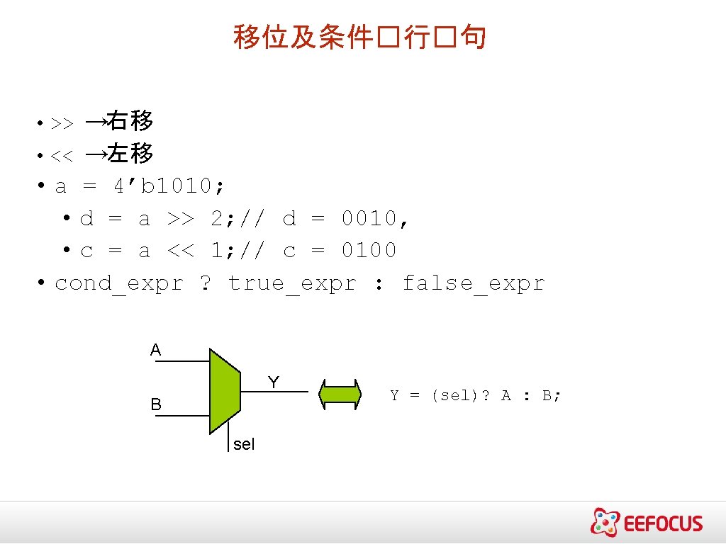
Verilog www eefocus com Specification Behavioral description RTL

Verilog基� 硬核���培� www. eefocus. com


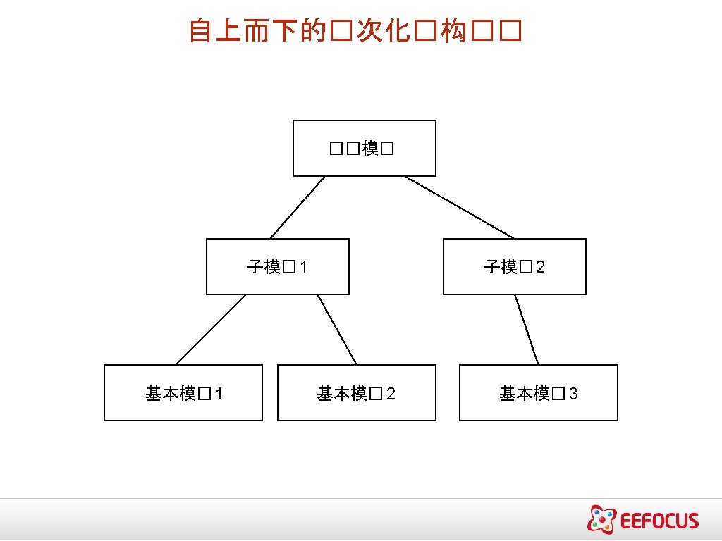
芯片��流程 Specification Behavioral description RTL description Functional verification & test Logic synthesis Gate level netlist Logic verification and testing Floor planning, auto place & route Physical layout Layout verification Implementation


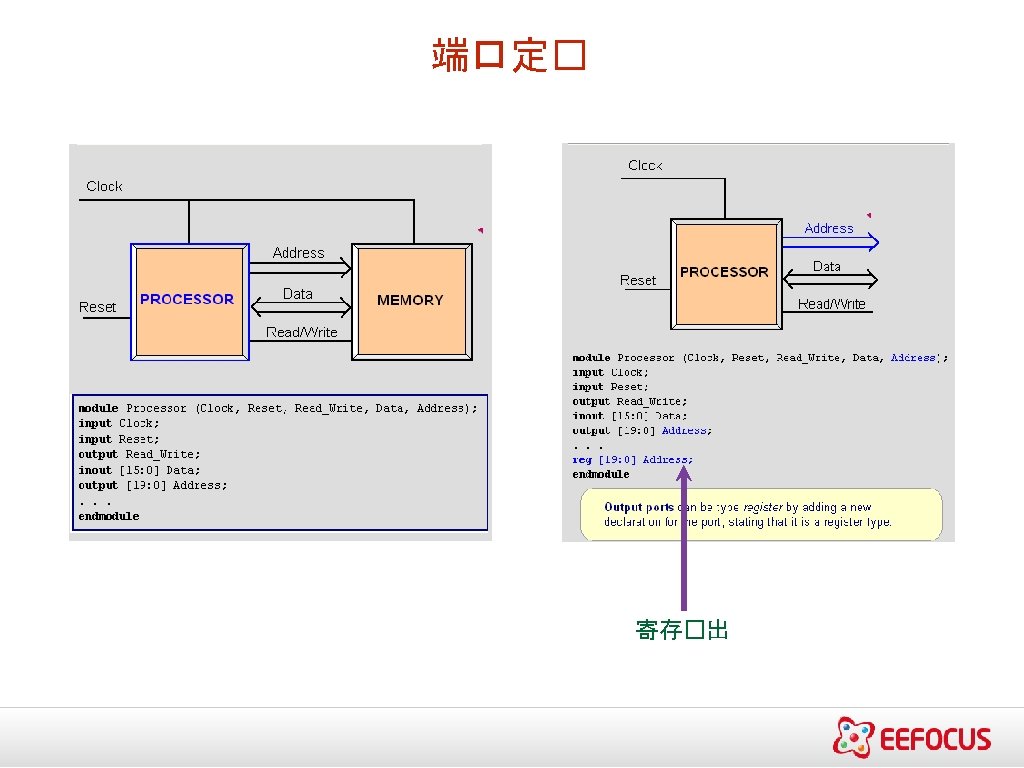
关�� 所有关��都是用小写字母来定� 例如 : • module, endmodule • input, output, inout • reg, integer, real, time • not, and, nand, or, nor, xor • parameter • begin, end • fork, join • specify, h • • • module – Verilog��中的基��,用于构建 ��中的�次化 endmodule – �束一个模�,不是一个�句 Module Declaration • module_name (module_port, …); • Example: module full_adder (A, B, c_in, c_out, S); �入定�: • 向量 • input list of input identifiers; • 例如: input A, B, c_in; • 矢量 • input[范� ] list of input identifiers; • 例如: input[15: 0] A, B, data; �出定�: • 向量�例 : output c_out, OV, MINUS; • 矢量�例 : output[7: 0] ACC, REG_IN, data_out;

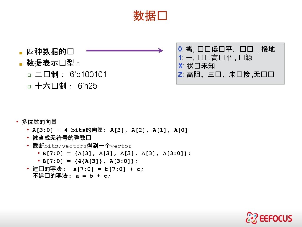
Verilog的数字表示 <位� >’<基数> <� > 位数 2�制 → b或B 8�制 → o 或 O 10�制 → d or D 16�制 → h or H ��的字符 0 -f, x, z 8’h ax = 1010 xxxx 12’o 3 zx 7 = 011 zzzxxx 11112’h 046 - 12位�的 16�制 数 Verilog的数�是没有符号的: 例如:C[4: 0] = A[3: 0] + B[3: 0]; if A = 0110 (6) and B = 1010(-6) C = 10000 not 0000 i. e. , B is zero-padded, not sign-extended
![�量的多种形式 ▪ Wires和registers可以是位、向量以及数� wire a; //一个��的 wire tri [15: 0] dbus; // 16 -bit](http://slidetodoc.com/presentation_image_h/9521a5632a98ff3986f3c347248b5dda/image-10.jpg "�量的多种形式 ▪ Wires和registers可以是位、向量以及数� wire a; //一个��的 wire tri [15: 0] dbus; // 16 -bit")
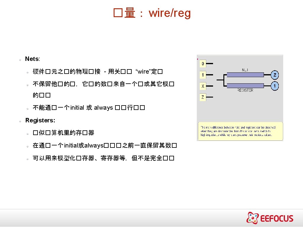
�量的多种形式 ▪ Wires和registers可以是位、向量以及数� wire a; //一个��的 wire tri [15: 0] dbus; // 16 -bit 三��� try #(5, 4, 8) b; // �延�的 Wire reg [-1: 4] vec; // 6 -bit的register(寄存器) triage (small) q; // Wire stores a small charge integer imem[0: 1023]; // 1024整数的数� reg [31: 0] dcache[0: 63]; // 一个 32 -bit 的存�器

�延声明和事件控制 延�声明 - 以一个#符号�明 - Delays the execution of the statement immediately after - Inertial delay model (ignores glitches) - Additive with blocking statements 事件控制声明: - Edge sensitive, represented with a @ sign - Delays the execution until expression transitions Ex. always @(clock) always @(posedge clock) always @(a or b) - Level sensitive, represented with wait statement Ex. always wait (enable) #20 cnt = cnt + 1; □ ��延� ■ �个延� : and #3 G 1 (y, a, b, c); ■ ■ 上升/下降延� and #(3, 5) G 2 (y, a, b) Rise/Fall/Turnoff buff 0 #(3, 6. 5) (y, x_in, en) Rise/Fall/Turnoff with Min: typ: Max buff 1 #(3: 4: 5, 4: 5: 6, 7: 8: 9) (y, x_in, en);

��运算 • && → ��与 AND • || → ��或 OR • ! → ��非 NOT • Operands evaluated to ONE bit value: 0, 1 or x • Result is ONE bit value: 0, 1 or x A = 1; A && B → 1 && 0 → 0 B = 0; A || !B → 1 || 1 → 1 C = x; C || B → x || 0 → x but C&&B=0
; input A, B;")
�例 - 比�器 module Compare 1 (A, B, Equal, Alarger, Blarger); input A, B; output Equal, Alarger, Blarger; assign Equal = (A & B) | (~A & ~B); assign Alarger = (A & ~B); assign Blarger = (~A & B); endmodule // 通� 4个 1位的比� 器构建一个 4位的比� 器 module Compare 4(A 4, B 4, Equal, Alarger, Blarger); input [3: 0] A 4, B 4; output Equal, Alarger, Blarger; wire e 0, e 1, e 2, e 3, Al 0, Al 1, Al 2, Al 3, B 10, Bl 1, Bl 2, Bl 3; Compare 1 cp 0(A 4[0], cp 1(A 4[1], cp 2(A 4[2], cp 3(A 4[3], B 4[0], B 4[1], B 4[2], B 4[3], e 0, e 1, e 2, e 3, assign Equal = (e 0 & e 1 & e 2 assign Alarger = (Al 3 | (Al 2 (Al 1 & e 3 & (Al 0 & e 3 & assign Blarger = (~Alarger & endmodule Al 0, Al 1, Al 2, Al 3, Bl 0); Bl 1); Bl 2); Bl 3); & e 3); & e 3) | e 2 & e 1)); ~Equal);
![Verilog持��� assign A = X | (Y & ~Z); assign B[3: 0] = 4'b](http://slidetodoc.com/presentation_image_h/9521a5632a98ff3986f3c347248b5dda/image-20.jpg "Verilog持��� assign A = X | (Y & ~Z); assign B[3: 0] = 4'b")
Verilog持��� assign A = X | (Y & ~Z); assign B[3: 0] = 4'b 01 XX; assign C[15: 0] = 16'h 00 ff; use of Boolean operators (~ for bit-wise, ! for logical negation) bits can take on four values (0, 1, X, Z) variables can be n-bits wide (MSB: LSB) assign #3 {Cout, S[3: 0]} = A[3: 0] + B[3: 0] + Cin; use of arithmetic operator multiple assignment (concatenation) delay of performing computation, only used by simulator, not synthesis

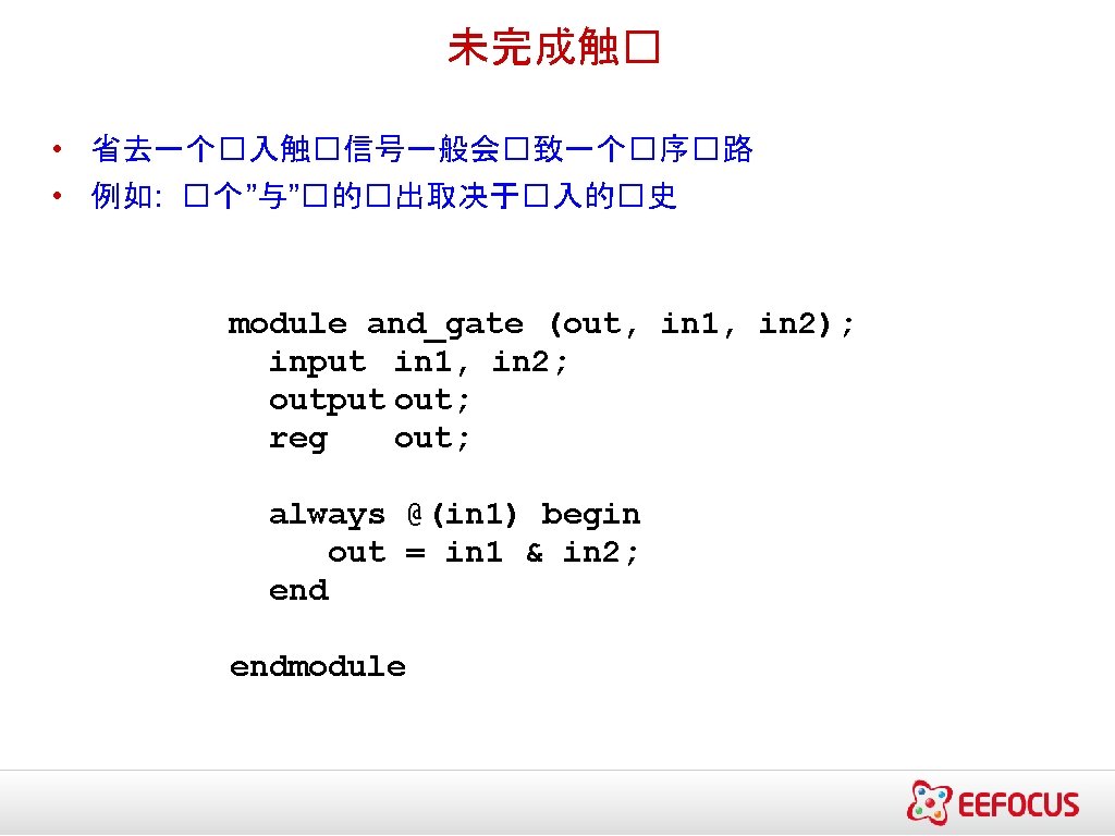
always block • always block • Always waiting for a change to a trigger signal • Then executes the body • Procedure that describes the function of a circuit • Can contain many statements including if, for, while, case • Statements in the always block are executed sequentially • (Continuous assignments <= are executed in parallel) • Entire block is executed at once • Final result describes the function of the circuit for current set of inputs • intermediate assignments don’t matter, only the final result • begin/end used to group statements module and_gate (out, in 1, in 2); input in 1, in 2; output out; reg out; Not a real register!! A Verilog register Needed because of assignment in always block always @(in 1 or in 2) begin out = in 1 & in 2; endmodule Specifies when block is executed I. e. , triggered by which signals

If // Simple 4: 1 mux module mux 4 (sel, A, B, C, D, Y); input [1: 0] sel; // 2 -bit control signal input A, B, C, D; output Y; reg Y; // target of assignment always @(sel or A or B or C or D) if (sel == 2’b 00) Y = A; else if (sel == 2’b 01) Y = B; else if (sel == 2’b 10) Y = C; else if (sel == 2’b 11) Y = D; endmodule 另外一种方式 // Simple 4: 1 mux module mux 4 (sel, A, B, C, D, Y); input [1: 0] sel; // 2 -bit control signal input A, B, C, D; output Y; reg Y; // target of assignment always @(sel or A or if (sel[0] == 0) if (sel[1] == 0) else endmodule B or C or D) Y = A; Y = B; Y = C; Y = D;
 • 缺省的case可以用到 // Simple 4")
Case - 1 • �序�行 • 只有第一个匹配的『case』被�行 (implicit break) • 缺省的case可以用到 // Simple 4 -1 mux module mux 4 (sel, A, B, C, D, Y); input [1: 0] sel; // 2 -bit control signal input A, B, C, D; output Y; reg Y; // target of assignment always @(sel case (sel) 2’b 00: Y 2’b 01: Y 2’b 10: Y 2’b 11: Y endcase endmodule or A or B or C or D) = = A; B; C; D; Conditions tested in top to bottom order
 module encode (A,")
Case - 2 // Simple binary encoder (input is 1 hot) module encode (A, Y); input [7: 0] A; // 8 -bit input vector output [2: 0] Y; // 3 -bit encoded output reg [2: 0] Y; // target of assignment // Priority encoder module encode (A, Y); input [7: 0] A; input vector output [2: 0] Y; encoded output reg [2: 0] Y; of assignment always @(A) case (A) 8’b 00000001: Y = 0; 8’b 00000010: Y = 1; 8’b 00000100: Y = 2; 8’b 00001000: Y = 3; 8’b 00010000: Y = 4; 8’b 00100000: Y = 5; 8’b 01000000: Y = 6; 8’b 10000000: Y = 7; default: Y = 3’b. XXX; Don’t care when input is not 1 -hot endcase endmodule always @(A) case (1’b 1) A[0]: Y = A[1]: Y = A[2]: Y = A[3]: Y = A[4]: Y = A[5]: Y = A[6]: Y = A[7]: Y = default: Y = care when input is endcase endmodule // // 8 -bit // 3 -bit // target 0; 1; 2; 3; 4; 5; 6; 7; 3’b. XXX; // Don’t all 0’s
![Case - 3 // simple encoder module encode (A, Y); input [7: 0] A;](http://slidetodoc.com/presentation_image_h/9521a5632a98ff3986f3c347248b5dda/image-26.jpg "Case - 3 // simple encoder module encode (A, Y); input [7: 0] A;")
Case - 3 // simple encoder module encode (A, Y); input [7: 0] A; output [2: 0] Y; reg [2: 0] Y; • always @(A) case (1’b 1) case A[0]: Y A[1]: Y A[2]: Y A[3]: Y A[4]: Y A[5]: Y A[6]: Y A[7]: Y default: Y is all 0’s endcase endmodule // 8 -bit input vector // 3 -bit encoded output // target of assignment // synthesis parallel- = = = = = 0; 1; 2; 3; 4; 5; 6; 7; 3’b. X; // Don’t care when input Like case, but cases can include ‘X’ • X bits not used when evaluating the cases • In other words, you don’t care about those bits! // Priority encoder module encode (A, valid, Y); input [7: 0] A; // 8 -bit input vector output [2: 0] Y; // 3 -bit encoded output valid; // Asserted when an input is not all 0’s reg [2: 0] Y; // target of assignment reg valid; always @(A) begin valid = 1; casex (A) 8’b. XXXXXXX 1: Y = 8’b. XXXXXX 10: Y = 8’b. XXXXX 100: Y = 8’b. XXXX 1000: Y = 8’b. XXX 10000: Y = 8’b. XX 100000: Y = 8’b. X 1000000: Y = 8’b 10000000: Y = default: begin valid = 0; Y = 3’b. X; input is all 0’s endcase endmodule 0; 1; 2; 3; 4; 5; 6; 7; // Don’t care when
![For/repeat/forever // simple encoder module encode (A, Y); input [7: 0] A; bit input](http://slidetodoc.com/presentation_image_h/9521a5632a98ff3986f3c347248b5dda/image-27.jpg "For/repeat/forever // simple encoder module encode (A, Y); input [7: 0] A; bit input")
For/repeat/forever // simple encoder module encode (A, Y); input [7: 0] A; bit input vector output [2: 0] Y; bit encoded output reg [2: 0] Y; target of assignment // 8// 3// integer i; // Temporary variables for program only reg [7: 0] test; always @(A) begin test = 8 b’ 00000001; Y = 3’b. X; for (i = 0; i < 8; i = i + 1) begin if (A == test) Y = i; test = test << 1; end endmodule • while (expression) statement • Execute statement while expression is true • repeat (expression) statement • Execute statement a fixed number of times • forever statement • Execute statement forever

另一个Behavioral的例子 • Computing Conway’s Game of Life rule • Cell with no neighbors or 4 neighbors dies; with 2 -3 neighbors lives module life (neighbors, self, out); input self; input [7: 0] neighbors; output out; reg out; integers are temporary compiler variables integer count; integer i; always block is executed instantaneously, if there are no delays only the final result is used always @(neighbors or self) begin count = 0; for (i = 0; i<8; i = i+1) count = count + neighbors[i]; out = 0; out = out | (count == 3); out = out | ((self == 1) & (count == 2)); endmodule
 module main; reg a, b, c; wire sum, carry; fulladder add(a,")
��台 (test bench) module main; reg a, b, c; wire sum, carry; fulladder add(a, b, c, sum, carry); initial begin a = 0; b = 0; c = 0; #5 a = 0; b = 1; c = 0; #5 a = 1; b = 0; c = 1; #5 a = 1; b = 1; c = 1; #5 endmodule

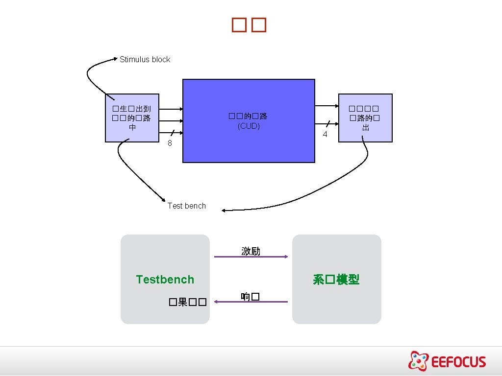
��模�的�构 ■ ■ ■ module <test module name> ; // 数据� 型声明 // Instantiate module ( � 用被�� 的模� ) // 施加激励 // � 示� 果 endmodule • ��台�生�入激励信号,也�常包括�数据的�察 module stimulus; reg clk; reg reset; wire[3: 0] q; // instantiate the design block ripple_carry_counter r 1(q, clk, reset); // Control the clock initial clk = 1'b 0; always #5 clk = ~clk; // Control the reset initial begin reset = 1'b 1; #15 reset = 1'b 0; #180 reset = 1'b 1; #10 reset = 1'b 0; #20 $stop; end // Monitor the outputs initial $monitor($time, " Output q = %d", q); endmodule
 run until they stop at one of")
仿真 仿真行� ▪ Concurrent processes (initial, always) run until they stop at one of the followin ▪ Scheduled using an event queue ▪ Non-preemptive, no priorities ▪ #42 ▪ A process must explicitly request a context switch • ▪ Events at a particular time unordered Schedule process to resume 42 time units from now ▪ wait(cf & of) • Resume when expression “cf & of” becomes true ▪ Scheduler runs each event at the current time, possibly scheduling more as a result ▪ @(a or b or y) • Resume when a, b, or y changes ▪ @(posedge clk) • Resume when clk changes from 0 to 1 两种�型的事件 ▪ Evaluation events compute functions of inputs ▪ Update events change outputs ▪ Split necessary for delays, nonblocking assignments, etc. Evaluation event reads values of b and c, adds them, and schedules an update event Update event writes new value of a and schedules any evaluation events that are sensitive to a change on a a <= b + c

仿真 ▪ Infinite loops are possible and the simulator does not check for them ▪ This runs forever: no context switch allowed, so ready can never change while (~ready) count = count + 1; ▪ Instead, use wait(ready); ▪ Race conditions abound in Verilog ▪ These can execute in either order: final value of a undefined: always @(posedge clk) a = 0; always @(posedge clk) a = 1; ▪ Semantics of the language closely tied to simulator implementation ▪ Context switching behavior convenient for simulation, not always best way to model ▪ Undefined execution order convenient for implementing event queue

Verilog基本�元 • 只是基本的��� – and – or – not – buf – xor – nand – nor – xnor – bufif 1, bufif 0 – notif 1, notif 0

所有���的 Verilog�� • • • module gates(a, b, y 1, y 2, y 3, y 4, y 5, y 6, y 7); input [3: 0] a, b; output [3: 0] y 1, y 2, y 3, y 4, y 5, y 6, y 7; /* 7种不同的��� 作于 4位的��上 */ assign y 1= ~a; // NOT gate assign y 2= a & b; // AND gate assign y 3= a | b; // OR gate assign y 4= ~(a & b); // NAND gate assign y 5= ~(a | b); // NOR gate assign y 6= a ^ b; // XOR gate assign y 7= ~(a ^ b); // XNOR gate endmodule
;")
示例 - 加法器 A A S Half Adder B module half_adder(S, C, A, B); output S, C; input A, B; S B C wire S, C, A, B; C assign S = A ^ B; assign C = A & B; endmodule in 1 in 2 A t B Half Adder 1 ha 1 S C I 1 I 2 A B Half Adder ha 2 sum S C I 3 cout cin module full_adder(sum, cout, in 1, in 2, cin); output sum, cout; input in 1, in 2, cin; Module name wire sum, cout, in 1, in 2, cin; wire I 1, I 2, I 3; half_adder ha 1(I 1, I 2, in 1, in 2); half_adder ha 2(sum, I 3, I 1, cin); assign cout = I 2 || I 3; endmodule Instance name

�例 : 全加器 in 1 A in 2 B Half Adder 1 ha 1 I 1 S C I 2 A B Half Adder ha 2 sum S C I 3 cout cin module full_adder(sum, cout, in 1, in 2, cin); output sum, cout; input in 1, in 2, cin; Module name wire sum, cout, in 1, in 2, cin; wire I 1, I 2, I 3; half_adder ha 1(I 1, I 2, in 1, in 2); half_adder ha 2(sum, I 3, I 1, cin); assign cout = I 2 || I 3; endmodule Instance name
 – They are")
�� • Continuous assignments assign values to nets (vector and scalar) – They are triggered whenever simulation causes the value of the right-hand side to change – Keyword “assign” e. g. assign out = in 1 & in 2; • Procedural assignments drive values onto registers (vector and scalar) – They Occur within procedures such as always and initial – They are triggered when the flow of execution reaches them (like in C) – Blocking and Non-Blocking procedural assignments • Procedural Assignments – Blocking assignment statement (= operator) acts much like in traditional programming languages. The whole statement is done before control passes on to the next statement – Nonblocking assignment statement (<= operator) evaluates all the righthand sides for the current time unit and assigns the left-hand sides at the end of the time unit
 – Expression specifies the time duration between initially encountering")
基于延�的定�控制 • Delay Control (#) – Expression specifies the time duration between initially encountering the statement and when the statement actually executes. – Delay in Procedural Assignments • Inter-Statement Delay • Intra-Statement Delay – For example: • Inter-Statement Delay #10 A = A + 1; • Intra-Statement Delay A = #10 A + 1;
 if (expr 1) true_stmt 1; else if (expr 2) true_stmt 2;")
�序表述: if/case (expr) if (expr 1) true_stmt 1; else if (expr 2) true_stmt 2; . . else def_stmt; item_1, . . , item_n: stmt 1; item_n+1, . . , item_m: stmt 2; . . default: def_stmt; endcase �使能控制的 3 -to 8�� module decoder(o, enb_, sel) ; output [7: 0] o ; input enb_ ; input [2: 0] sel ; E. g. 4 -to-1 mux: module mux 4_1(out, in, sel); output out; input [3: 0] in; input [1: 0] sel; reg out; wire [3: 0] in; wire [1: 0] sel; always @(in or sel) if (sel == 0) out = in[0]; else if (sel == 1) out = in[1]; else if (sel == 2) out = in[2]; else out = in[3]; endmodule always @(in or sel) case (sel) 0: out = in[0]; 1: out = in[1]; 2: out = in[2]; 3: out = in[3]; endcase endmodule reg [7: 0] o ; always @ (enb_ or sel) if(enb_) o = 8'b 1111_1111 ; else case(sel) 3'b 000 : o = 8'b 1111_1110 3'b 001 : o = 8'b 1111_1101 3'b 010 : o = 8'b 1111_1011 3'b 011 : o = 8'b 1111_0111 3'b 100 : o = 8'b 1110_1111 3'b 101 : o = 8'b 1101_1111 3'b 110 : o = 8'b 1011_1111 3'b 111 : o = 8'b 0111_1111 default : o = 8'bx ; endcase endmodule ; ; ; ;

矢量 • Nets and Registers can be declared as vectors • If no bitwidth is specified, 1 bit is assumed wire [7: 0] a; reg [0: 31] addr 1, addr 2; • Subsets of bits can be selected addr 1[2: 0] = addr 2[3: 1];

其它数据�型 • Verilog allows integers, real, and time types • Arrays can be made from other types - Arrays can be multidimensional - A vector is conceptually a single elements with many bits - An array is many elements put together wire [7: 0] x; // a vector wire x [7: 0]; // an array wire [7: 0] x [7: 0]; // an array of vectors wire x[7: 0]; // a two dimensional array • Parameters are constants parameter line_width=80;

Dataflow Descriptions, Continuous Assignments assign out = i 1 & i 2; module edge_dff(q, qbar, d, clk, clear); • Use the assign keyword (in most cases) • Left hand side must be a net of some kind (scalar or vector), not a register • Right hand side can be registers, nets, or function calls • Continuous assignments are always active. Execution hard to trace • They are evaluated whenever a right hand side operand changes value • Delays (inertial) can be added to represent component delays assign #10 out = i 1 & i 2; • Continuous assignment can be implicit in a net declaration wire out = i 1 & i 2; // Inputs and outputs output q, qbar; input d, clk, clear; // Internal variables wire s, sbar, r, rbar, cbar; //Make complement of clear assign cbar = ~clear; // Input latches assign sbar = ~(rbar & s), s = ~(sbar & cbar & ~clk), r = ~(rbar & ~clk & s), rbar = ~(r & cbar & d); // Output latch assign q = ~(s & qbar), qbar = ~(q & r & cbar); endmodule

Behavioral Modeling, Structured Procedures Always blocks and initial blocks - Parallel constructs: all blocks can execute in parallel Initial blocks - The block executes only once - By default, starts at time 0 (but this can be changed) - Often used for initialization module stimulus; reg x, y, a, b, m; initial begin #5 a = 1'b 1; #25 b = 1'b 0; end begin initial … imperative statements … end begin #10 x = 1'b 0; #25 y = 1'b 1; Runs when simulation starts end Terminates when control reaches the endmodule Good for providing stimulus Always blocks - The block executes in an infinite loop - By default, starts at time 0 (but this can be changed) - Represents a concurrent hardware block - Needs a delay always begin module clock_gen; … imperative statements … reg clock; initial end clock = 1'b 0; always Runs when simulation starts #10 clock = Restarts when control reaches the end ~clock; Good for modeling/specifying hardware initial #1000 $finish; endmodule

Initial and Always ▪ Run until they encounter a delay initial begin #10 a = 1; b = 0; #10 a = 0; b = 1; end ▪ or a wait for an event always @(posedge clk) q = d; always begin wait(i); a = 0; wait(~i); a = 1; end

Procedural Statements ▪ Verilog has two types of procedural assignment ▪ Fundamental problem: • In a synchronous system, all flip-flops sample simultaneously • In Verilog, always @(posedge clk) blocks run in some undefined sequence Non-Blocking Assignments - Represented with a <= sign Blocking Assignments - All non-blocking assignments are - Represented with a = sign executed in parallel - All blocking assignments are executed in - Try not to mix with blocking sequence assignments module dummy; reg x, y, z; reg [15: 0] reg_a, reg_b; integer count; initial begin x = 0; y = 1; z = 1; count = 0; reg_a = 16'b 0; reg_b = reg_a; reg_a[2] = #15 1; reg_b[15: 13] = #10 {x, y, z}; count = count + 1; end module dummy; reg x, y, z; reg [15: 0] reg_a, reg_b; integer count; initial begin x = 0; y = 1; z = 1; count = 0; reg_a = 16'b 0; reg_b = reg_a; reg_a[2] <= #15 1; reg_b[15: 13] <= #10 {x, y, z}; count = count + 1; end

�序�路�� Inputs Combinational circuit – a feedback path – the state of the sequential circuits – the state transition • synchronous circuits • asynchronous circuits Examples-D latch D flip-flop register Outputs Memory elements
 • • • Initial")
Two Main Components of Verilog ▪ Concurrent, event-triggered processes (behavioral) • • • Initial and Always blocks Imperative code that can perform standard data manipulation tasks (assignment, if-then, case) Processes run until they delay for a period of time or wait for a triggering event ▪ Structure (Plumbing) • • Verilog program build from modules with I/O interfaces Modules may contain instances of other modules Modules contain local signals, etc. Module configuration is static and all run concurrently
; output f; input a, b,")
Multiplexer Built With Always module mux(f, a, b, sel); output f; input a, b, sel; reg f; always @(a or b or sel) if (sel) f = a; else f = b; Modules may contain one or more always blocks Sensitivity list contains signals whose change triggers the execution of the block a endmodule f b sel Copyright © 2001 Stephen A. Edwards All rights reserved
; output f; input a, b,")
Multiplexer Built With Always module mux(f, a, b, sel); output f; input a, b, sel; reg f; A reg behaves like memory: holds its value until imperatively assigned otherwise always @(a or b or sel) if (sel) f = a; else f = b; Body of an always block contains traditional imperative code a endmodule f b sel Copyright © 2001 Stephen A. Edwards All rights reserved
; output f; input a, b,")
Mux with Continuous Assignment module mux(f, a, b, sel); output f; input a, b, sel; LHS is always set to the value on the RHS Any change on the right causes reevaluation assign f = sel ? a : b; endmodule a f b sel Copyright © 2001 Stephen A. Edwards All rights reserved
; output f; input a, b,")
Mux with User-Defined Primitive primitive mux(f, a, b, sel); output f; input a, b, sel; table 1? 0 : 1; 0? 0 : 0; ? 11 : 1; ? 01 : 0; 11? : 1; 00? : 0; endtable endprimitive Behavior defined using a truth table that includes “don’t cares” This is a less pessimistic than others: when a & b match, sel is ignored (others produce X) a f b sel Copyright © 2001 Stephen A. Edwards All rights reserved

Structural Modeling Copyright © 2001 Stephen A. Edwards All rights reserved

Modules and Instances ▪ Basic structure of a Verilog module: module mymod(output 1, output 2, … input 1, input 2); output 1; output [3: 0] output 2; input 1; input [2: 0] input 2; … endmodule Copyright © 2001 Stephen A. Edwards All rights reserved Verilog convention lists outputs first
; ▪ look like mymod")
Instantiating a Module ▪ Instances of module mymod(y, a, b); ▪ look like mymod mm 1(y 1, a 1, b 1); // Connect-by-position mymod (y 2, a 1, b 1), (y 3, a 2, b 2); // Instance names omitted mymod mm 2(. a(a 2), . b(b 2), . y(c 2)); // Connect-by-name Copyright © 2001 Stephen A. Edwards All rights reserved
; output q; reg q; input clk, data;")
A Sequential Primitive dff( q, clk, data); output q; reg q; input clk, data; table // clk data q new-q (01) 0 : ? : 0; // Latch a 0 (01) 1 : ? : 1; // Latch a 1 (0 x) 1 : 1; // Hold when d and q both 1 (0 x) 0 : 0; // Hold when d and q both 0 (? 0) ? : ? : -; // Hold when clk falls ? (? ? ) : ? : -; // Hold when clk stable endprimitive Copyright © 2001 Stephen A. Edwards All rights reserved

Continuous Assignment ▪ Another way to describe combinational function ▪ Convenient for logical or datapath specifications wire [8: 0] sum; Define bus widths wire [7: 0] a, b; wire carryin; assign sum = a + b + carryin; Copyright © 2001 Stephen A. Edwards All rights reserved Continuous assignment: permanently sets the value of sum to be a+b+carryin Recomputed when a, b, or carryin changes
y = a; else y = b; case (op)")
Imperative Statements if (select == 1)y = a; else y = b; case (op) 2’b 00: y = a + b; 2’b 01: y = a – b; 2’b 10: y = a ^ b; default: y = ‘hxxxx; endcase Copyright © 2001 Stephen A. Edwards All rights reserved

Loops For Loops ▪ A increasing sequence of values on an output reg [3: 0] i, output; for ( i = 0 ; i <= 15 ; i = i + 1 ) begin output = i; #10; end While Loops ▪ A increasing sequence of values on an output reg [3: 0] i, output; i = 0; while (I <= 15) begin output = i; #10 i = i + 1; end

parameter length = 20; �数器�例. . . input rst; // These inputs/outputs represent reg a, b, c, d; input clk; // connections to the module. wire e; input cet; . . . input cep; always @(b or e) begin output [size-1: 0] count; a = b & e; output tc; b = a | b; #5 c = b; reg [size-1: 0] count; // Signals assigned d = #6 c ^ e; // within an always end // (or initial)block // must be of type reg wire tc; // Other signals are of type wire // The always statement below is a parallel // execution statement that // executes any time the signals // rst or clk transition from low to high always @ (posedge clk or posedge rst) The always clause above illustrates the other type of method of use, i. e. it executes whenever any of the entities in the list (the b or e) changes. When one of these changes, a is immediately assigned a new value, and due to the blocking assignment, b is assigned a new value afterward (taking into account the new value of a). After a delay of 5 time units, c is assigned the value of b and the value of c ^ e is tucked away in an invisible store. Then after 6 more time units, d is assigned the value that was tucked away. Signals that are driven from within a process (an initial or always block) must be of type reg. Signals that are driven from outside a process must be of type wire. The keyword reg does not necessarily imply a hardware register.
- Slides: 60