Verilog 1 Fundamentals FA FA module adder input
- Slides: 67
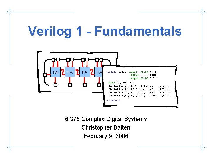
Verilog 1 - Fundamentals FA FA module adder( input [3: 0] A, B, output cout, output [3: 0] S ); wire c 0, c 1, c 2; FA fa 0( A[0], B[0], FA fa 1( A[1], B[1], FA fa 2( A[2], B[2], FA fa 3( A[3], B[3], 1’b 0, c 1, c 2, endmodule 6. 375 Complex Digital Systems Christopher Batten February 9, 2006 c 0, c 1, c 2, cout, S[0] S[1] S[2] S[3] ); );
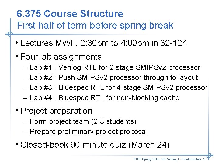
6. 375 Course Structure First half of term before spring break • Lectures MWF, 2: 30 pm to 4: 00 pm in 32 -124 • Four lab assignments – – Lab #1 : Verilog RTL for 2 -stage SMIPSv 2 processor Lab #2 : Push SMIPSv 2 processor through to layout Lab #3 : Bluespec RTL for 4 -stage SMIPSv 2 processor Lab #4 : Bluespec RTL for non-blocking cache • Project preparation – Form project team (2 -3 students) – Prepare preliminary project proposal • Closed-book 90 minute quiz (March 24) 6. 375 Spring 2006 • L 02 Verilog 1 - Fundamentals • 2
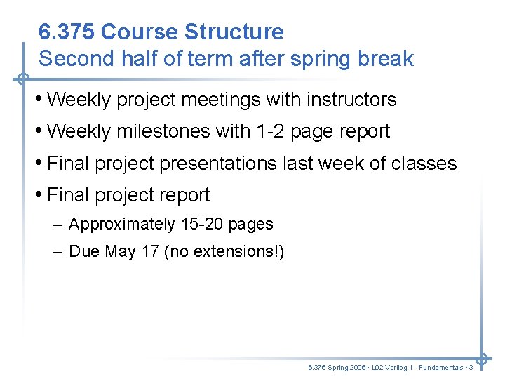
6. 375 Course Structure Second half of term after spring break • Weekly project meetings with instructors • Weekly milestones with 1 -2 page report • Final project presentations last week of classes • Final project report – Approximately 15 -20 pages – Due May 17 (no extensions!) 6. 375 Spring 2006 • L 02 Verilog 1 - Fundamentals • 3
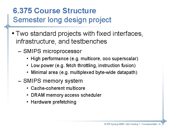
6. 375 Course Structure Semester long design project • Two standard projects with fixed interfaces, infrastructure, and testbenches – SMIPS microprocessor • High performance (e. g. multicore, ooo superscalar) • Low power (e. g. fetch throttling, instruction fusion) • Minimal area (e. g. multiplexed byte-wide datapath) – SMIPS memory system • Cache-coherent multicore • DRAM memory access scheduler • Hardware prefetching 6. 375 Spring 2006 • L 02 Verilog 1 - Fundamentals • 4
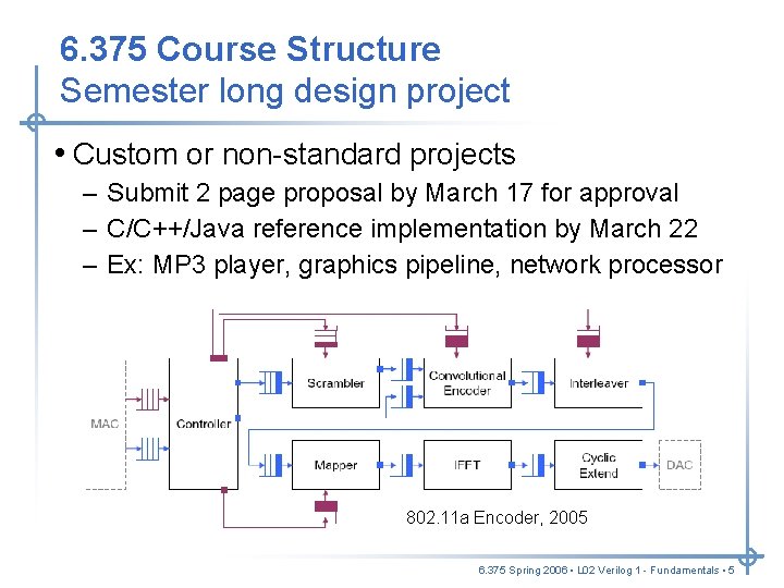
6. 375 Course Structure Semester long design project • Custom or non-standard projects – Submit 2 page proposal by March 17 for approval – C/C++/Java reference implementation by March 22 – Ex: MP 3 player, graphics pipeline, network processor 802. 11 a Encoder, 2005 6. 375 Spring 2006 • L 02 Verilog 1 - Fundamentals • 5
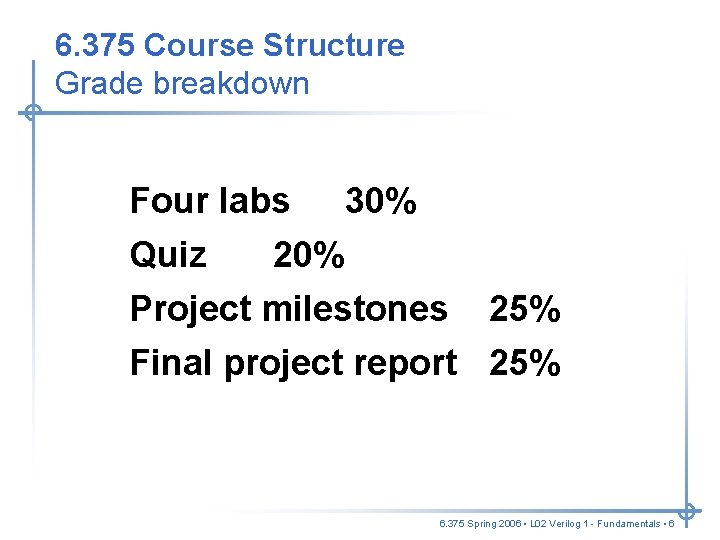
6. 375 Course Structure Grade breakdown Four labs 30% Quiz 20% Project milestones 25% Final project report 25% 6. 375 Spring 2006 • L 02 Verilog 1 - Fundamentals • 6
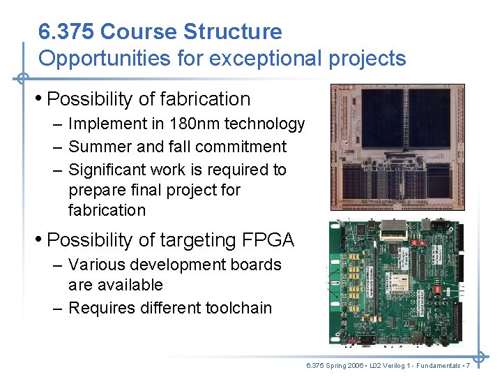
6. 375 Course Structure Opportunities for exceptional projects • Possibility of fabrication – Implement in 180 nm technology – Summer and fall commitment – Significant work is required to prepare final project for fabrication • Possibility of targeting FPGA – Various development boards are available – Requires different toolchain 6. 375 Spring 2006 • L 02 Verilog 1 - Fundamentals • 7
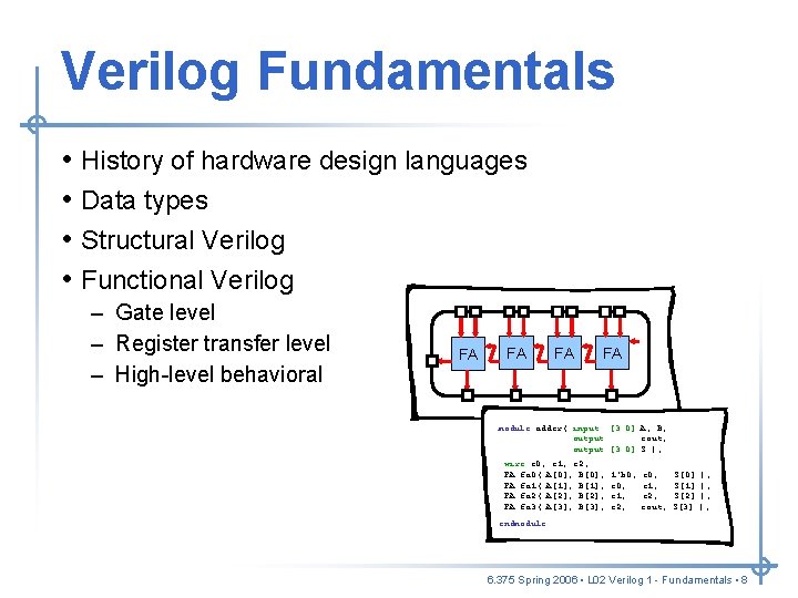
Verilog Fundamentals • • History of hardware design languages Data types Structural Verilog Functional Verilog – Gate level – Register transfer level – High-level behavioral FA FA module adder( input [3: 0] A, B, output cout, output [3: 0] S ); wire c 0, c 1, c 2; FA fa 0( A[0], B[0], FA fa 1( A[1], B[1], FA fa 2( A[2], B[2], FA fa 3( A[3], B[3], 1’b 0, c 1, c 2, c 0, c 1, c 2, cout, S[0] S[1] S[2] S[3] ); ); endmodule 6. 375 Spring 2006 • L 02 Verilog 1 - Fundamentals • 8
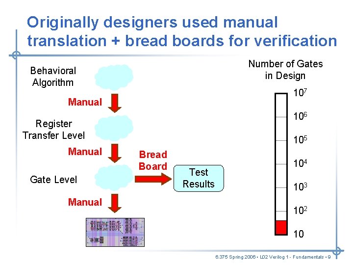
Originally designers used manual translation + bread boards for verification Number of Gates in Design Behavioral Algorithm 107 Manual 106 Register Transfer Level Manual Gate Level Manual 105 Bread Board Test Results 104 103 102 10 6. 375 Spring 2006 • L 02 Verilog 1 - Fundamentals • 9
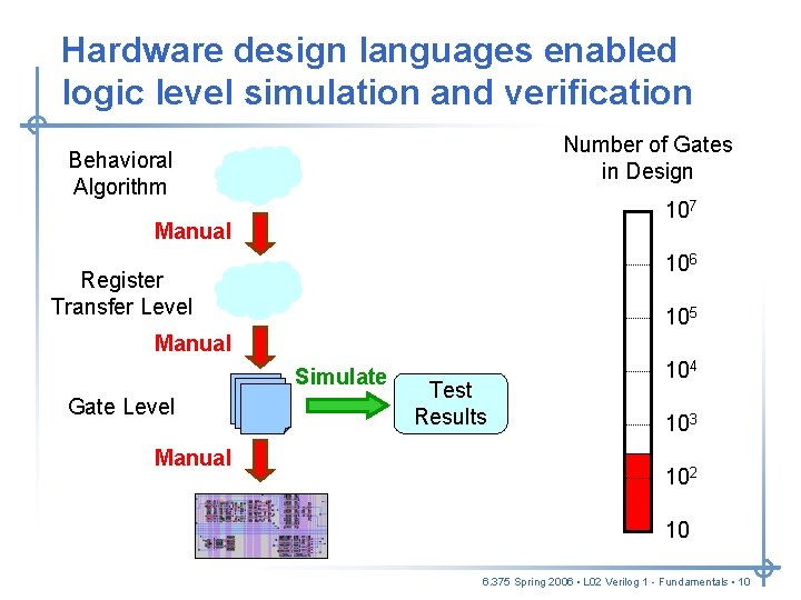
Hardware design languages enabled logic level simulation and verification Number of Gates in Design Behavioral Algorithm 107 Manual 106 Register Transfer Level 105 Manual Simulate Gate Level Manual Test Results 104 103 102 10 6. 375 Spring 2006 • L 02 Verilog 1 - Fundamentals • 10
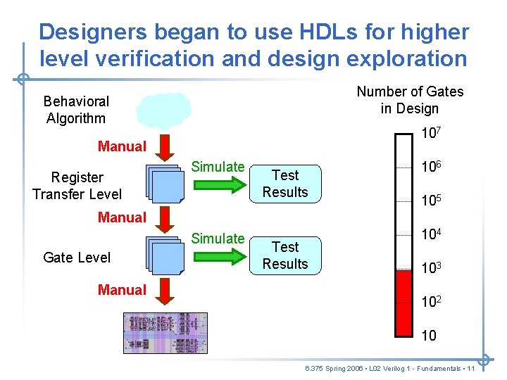
Designers began to use HDLs for higher level verification and design exploration Number of Gates in Design Behavioral Algorithm 107 Manual Register Transfer Level Simulate Test Results 106 105 Manual Simulate Gate Level Manual Test Results 104 103 102 10 6. 375 Spring 2006 • L 02 Verilog 1 - Fundamentals • 11
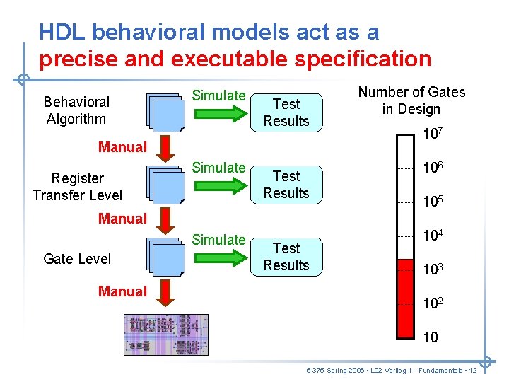
HDL behavioral models act as a precise and executable specification Behavioral Algorithm Simulate Test Results Manual Register Transfer Level Simulate Test Results Number of Gates in Design 107 106 105 Manual Simulate Gate Level Manual Test Results 104 103 102 10 6. 375 Spring 2006 • L 02 Verilog 1 - Fundamentals • 12
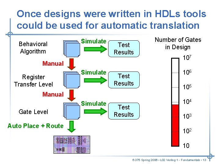
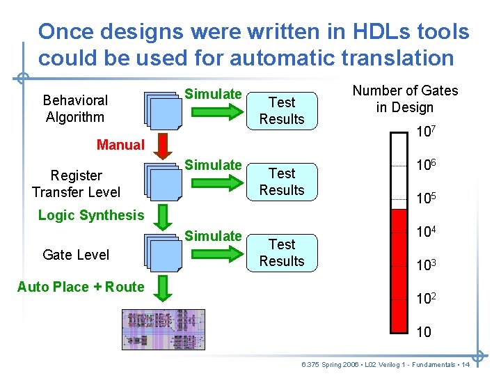
Once designs were written in HDLs tools could be used for automatic translation Behavioral Algorithm Simulate Test Results Manual Register Transfer Level Simulate Test Results Number of Gates in Design 107 106 105 Manual Simulate Gate Level Auto Place + Route Test Results 104 103 102 10 6. 375 Spring 2006 • L 02 Verilog 1 - Fundamentals • 13
Once designs were written in HDLs tools could be used for automatic translation Behavioral Algorithm Simulate Test Results Manual Register Transfer Level Simulate Test Results Number of Gates in Design 107 106 105 Logic Synthesis Simulate Gate Level Auto Place + Route Test Results 104 103 102 10 6. 375 Spring 2006 • L 02 Verilog 1 - Fundamentals • 14
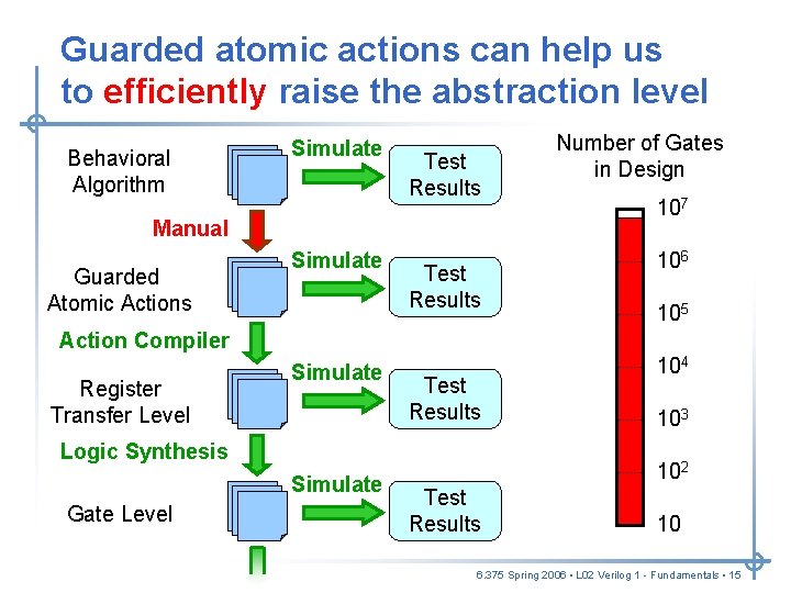
Guarded atomic actions can help us to efficiently raise the abstraction level Behavioral Algorithm Simulate Test Results Manual Guarded Atomic Actions Simulate Test Results Number of Gates in Design 107 106 105 Action Compiler Register Transfer Level Simulate Test Results Logic Synthesis Simulate Gate Level 104 103 102 Test Results 10 6. 375 Spring 2006 • L 02 Verilog 1 - Fundamentals • 15
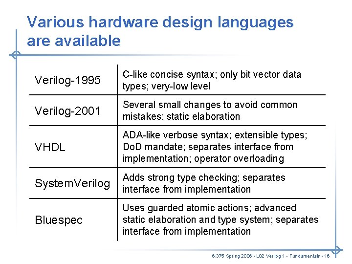
Various hardware design languages are available Verilog-1995 C-like concise syntax; only bit vector data types; very-low level Verilog-2001 Several small changes to avoid common mistakes; static elaboration VHDL ADA-like verbose syntax; extensible types; Do. D mandate; separates interface from implementation; operator overloading System. Verilog Adds strong type checking; separates interface from implementation Bluespec Uses guarded atomic actions; advanced static elaboration and type system; separates interface from implementation 6. 375 Spring 2006 • L 02 Verilog 1 - Fundamentals • 16
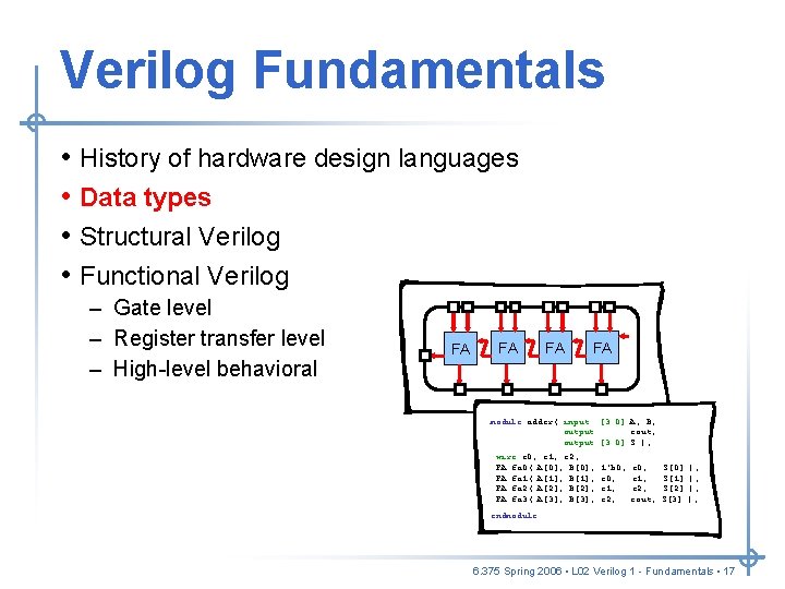
Verilog Fundamentals • • History of hardware design languages Data types Structural Verilog Functional Verilog – Gate level – Register transfer level – High-level behavioral FA FA module adder( input [3: 0] A, B, output cout, output [3: 0] S ); wire c 0, c 1, c 2; FA fa 0( A[0], B[0], FA fa 1( A[1], B[1], FA fa 2( A[2], B[2], FA fa 3( A[3], B[3], 1’b 0, c 1, c 2, c 0, c 1, c 2, cout, S[0] S[1] S[2] S[3] ); ); endmodule 6. 375 Spring 2006 • L 02 Verilog 1 - Fundamentals • 17
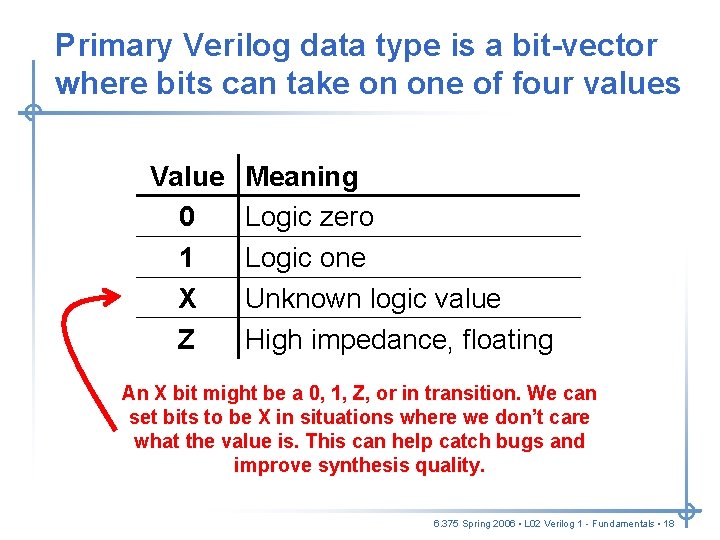
Primary Verilog data type is a bit-vector where bits can take on one of four values Value 0 1 X Z Meaning Logic zero Logic one Unknown logic value High impedance, floating An X bit might be a 0, 1, Z, or in transition. We can set bits to be X in situations where we don’t care what the value is. This can help catch bugs and improve synthesis quality. 6. 375 Spring 2006 • L 02 Verilog 1 - Fundamentals • 18
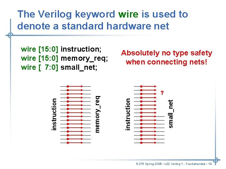
The Verilog keyword wire is used to denote a standard hardware net Absolutely no type safety when connecting nets! small_net ? instruction memory_req instruction wire [15: 0] instruction; wire [15: 0] memory_req; wire [ 7: 0] small_net; 6. 375 Spring 2006 • L 02 Verilog 1 - Fundamentals • 19
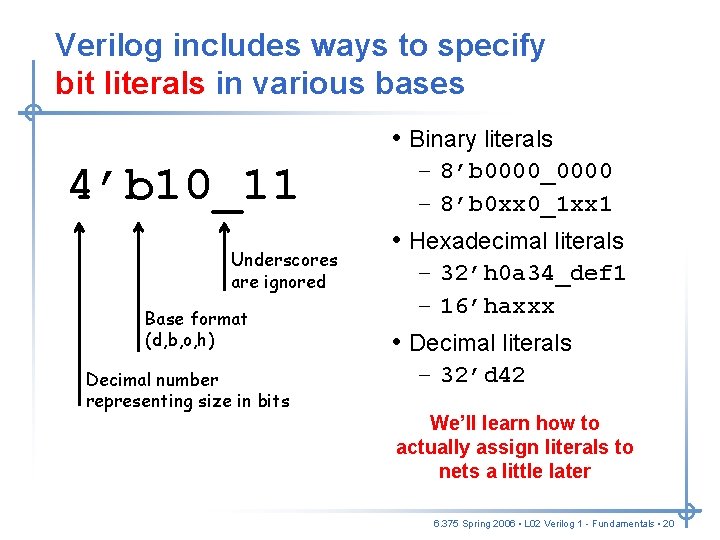
Verilog includes ways to specify bit literals in various bases • Binary literals 4’b 10_11 Underscores are ignored Base format (d, b, o, h) Decimal number representing size in bits – 8’b 0000_0000 – 8’b 0 xx 0_1 xx 1 • Hexadecimal literals – 32’h 0 a 34_def 1 – 16’haxxx • Decimal literals – 32’d 42 We’ll learn how to actually assign literals to nets a little later 6. 375 Spring 2006 • L 02 Verilog 1 - Fundamentals • 20
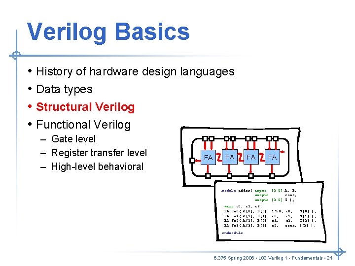
Verilog Basics • • History of hardware design languages Data types Structural Verilog Functional Verilog – Gate level – Register transfer level – High-level behavioral FA FA module adder( input [3: 0] A, B, output cout, output [3: 0] S ); wire c 0, c 1, c 2; FA fa 0( A[0], B[0], FA fa 1( A[1], B[1], FA fa 2( A[2], B[2], FA fa 3( A[3], B[3], 1’b 0, c 1, c 2, c 0, c 1, c 2, cout, S[0] S[1] S[2] S[3] ); ); endmodule 6. 375 Spring 2006 • L 02 Verilog 1 - Fundamentals • 21
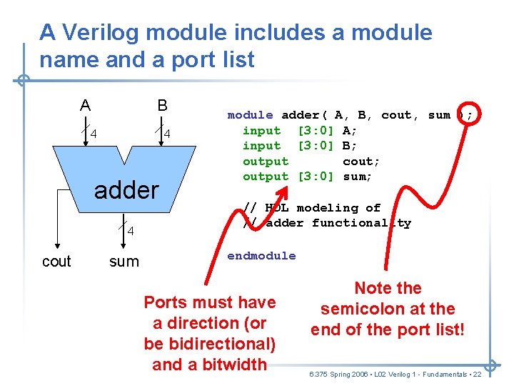
A Verilog module includes a module name and a port list A B 4 4 adder 4 cout sum module adder( A, B, cout, sum ); input [3: 0] A; input [3: 0] B; output cout; output [3: 0] sum; // HDL modeling of // adder functionality endmodule Ports must have a direction (or be bidirectional) and a bitwidth Note the semicolon at the end of the port list! 6. 375 Spring 2006 • L 02 Verilog 1 - Fundamentals • 22
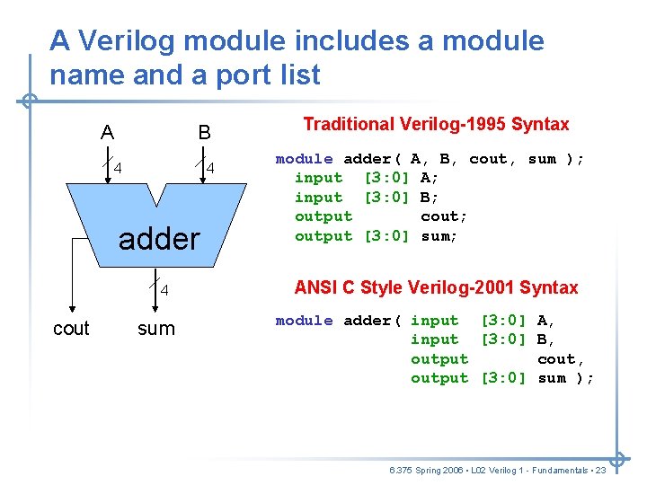
A Verilog module includes a module name and a port list A B 4 4 adder 4 cout sum Traditional Verilog-1995 Syntax module adder( A, B, cout, sum ); input [3: 0] A; input [3: 0] B; output cout; output [3: 0] sum; ANSI C Style Verilog-2001 Syntax module adder( input [3: 0] A, input [3: 0] B, output cout, output [3: 0] sum ); 6. 375 Spring 2006 • L 02 Verilog 1 - Fundamentals • 23
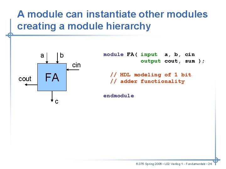
A module can instantiate other modules creating a module hierarchy a b cin cout FA c module FA( input a, b, cin output cout, sum ); // HDL modeling of 1 bit // adder functionality endmodule 6. 375 Spring 2006 • L 02 Verilog 1 - Fundamentals • 24
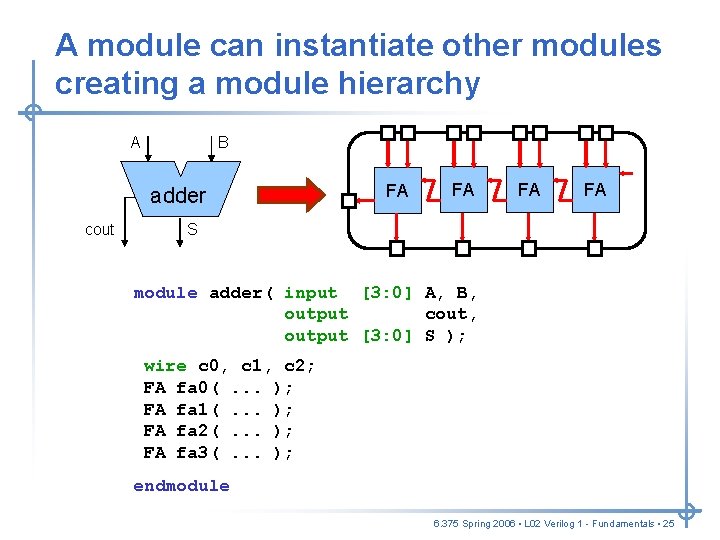
A module can instantiate other modules creating a module hierarchy A B adder cout FA FA S module adder( input [3: 0] A, B, output cout, output [3: 0] S ); wire c 0, c 1, c 2; FA fa 0(. . . ); FA fa 1(. . . ); FA fa 2(. . . ); FA fa 3(. . . ); endmodule 6. 375 Spring 2006 • L 02 Verilog 1 - Fundamentals • 25
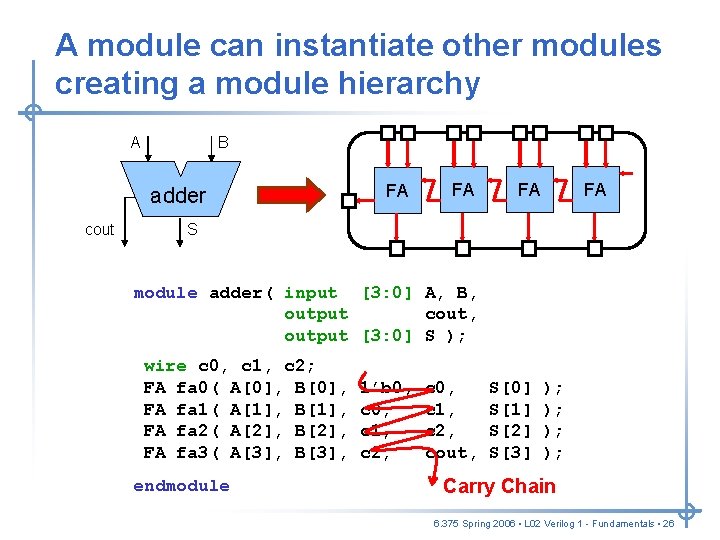
A module can instantiate other modules creating a module hierarchy A B adder cout FA FA S module adder( input [3: 0] A, B, output cout, output [3: 0] S ); wire c 0, c 1, c 2; FA fa 0( A[0], B[0], FA fa 1( A[1], B[1], FA fa 2( A[2], B[2], FA fa 3( A[3], B[3], endmodule 1’b 0, c 1, c 2, c 0, c 1, c 2, cout, S[0] S[1] S[2] S[3] ); ); Carry Chain 6. 375 Spring 2006 • L 02 Verilog 1 - Fundamentals • 26
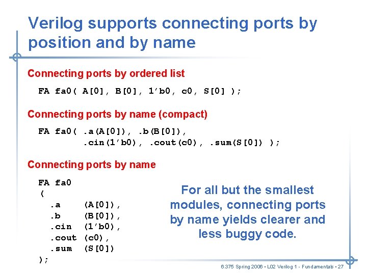
Verilog supports connecting ports by position and by name Connecting ports by ordered list FA fa 0( A[0], B[0], 1’b 0, c 0, S[0] ); Connecting ports by name (compact) FA fa 0(. a(A[0]), . b(B[0]), . cin(1’b 0), . cout(c 0), . sum(S[0]) ); Connecting ports by name FA fa 0 (. a. b. cin. cout. sum ); (A[0]), (B[0]), (1’b 0), (c 0), (S[0]) For all but the smallest modules, connecting ports by name yields clearer and less buggy code. 6. 375 Spring 2006 • L 02 Verilog 1 - Fundamentals • 27
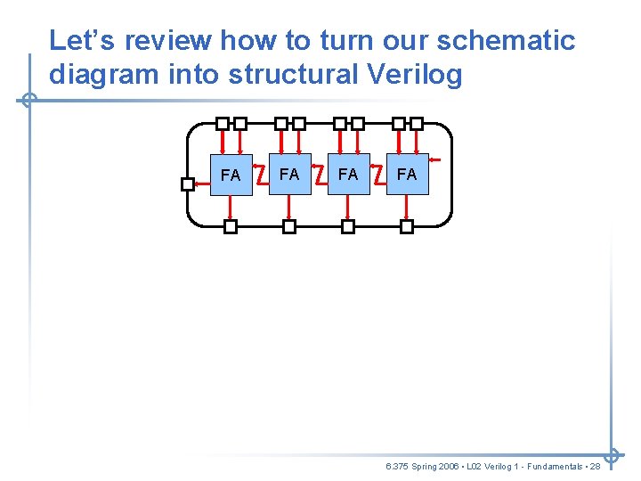
Let’s review how to turn our schematic diagram into structural Verilog FA FA 6. 375 Spring 2006 • L 02 Verilog 1 - Fundamentals • 28
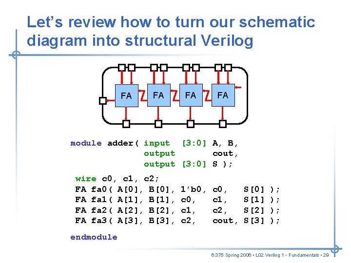
Let’s review how to turn our schematic diagram into structural Verilog FA FA ); [3: 0] A, B, module adder(. . . input output cout, output [3: 0] S ); wire c 0, c 1, c 2; FA fa 0( A[0], . . . ); B[0], FA fa 1( A[1], . . . ); B[1], FA fa 2( A[2], . . . ); B[2], FA fa 3( A[3], . . . ); B[3], 1’b 0, c 1, c 2, c 0, c 1, c 2, cout, S[0] S[1] S[2] S[3] ); ); endmodule 6. 375 Spring 2006 • L 02 Verilog 1 - Fundamentals • 29
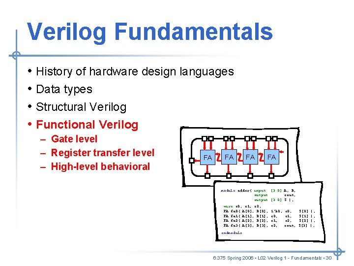
Verilog Fundamentals • • History of hardware design languages Data types Structural Verilog Functional Verilog – Gate level – Register transfer level – High-level behavioral FA FA module adder( input [3: 0] A, B, output cout, output [3: 0] S ); wire c 0, c 1, c 2; FA fa 0( A[0], B[0], FA fa 1( A[1], B[1], FA fa 2( A[2], B[2], FA fa 3( A[3], B[3], 1’b 0, c 1, c 2, c 0, c 1, c 2, cout, S[0] S[1] S[2] S[3] ); ); endmodule 6. 375 Spring 2006 • L 02 Verilog 1 - Fundamentals • 30
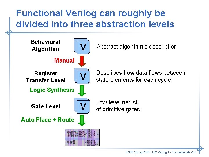
Functional Verilog can roughly be divided into three abstraction levels Behavioral Algorithm V Abstract algorithmic description V Describes how data flows between state elements for each cycle V Low-level netlist of primitive gates Manual Register Transfer Level Logic Synthesis Gate Level Auto Place + Route 6. 375 Spring 2006 • L 02 Verilog 1 - Fundamentals • 31
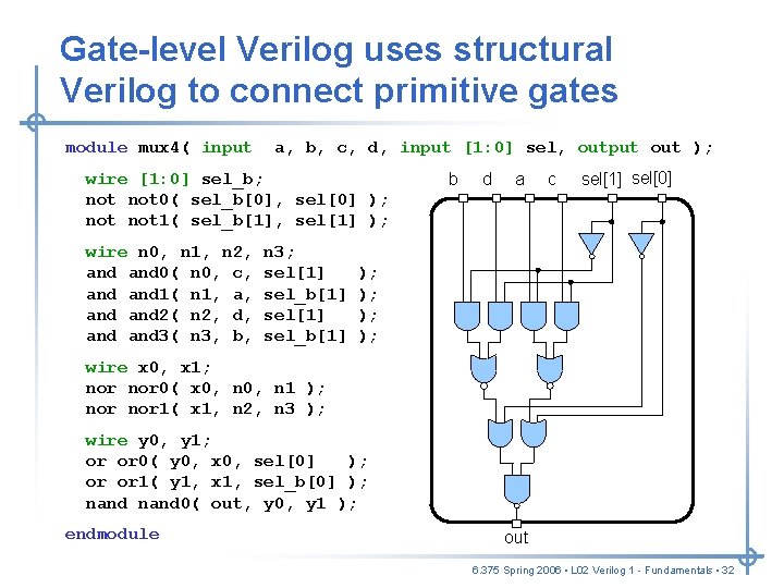
Gate-level Verilog uses structural Verilog to connect primitive gates module mux 4( input a, b, c, d, input [1: 0] sel, output out ); wire [1: 0] sel_b; not 0( sel_b[0], sel[0] ); not 1( sel_b[1], sel[1] ); wire n 0, n 1, n 2, and 0( n 0, c, and 1( n 1, a, and 2( n 2, d, and 3( n 3, b, n 3; sel[1] sel_b[1] b d a c sel[1] sel[0] ); ); wire x 0, x 1; nor 0( x 0, n 1 ); nor 1( x 1, n 2, n 3 ); wire y 0, y 1; or or 0( y 0, x 0, sel[0] ); or or 1( y 1, x 1, sel_b[0] ); nand 0( out, y 0, y 1 ); endmodule out 6. 375 Spring 2006 • L 02 Verilog 1 - Fundamentals • 32
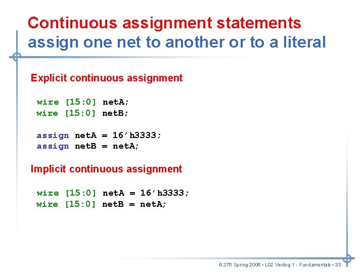
Continuous assignment statements assign one net to another or to a literal Explicit continuous assignment wire [15: 0] net. A; wire [15: 0] net. B; assign net. A = 16’h 3333; assign net. B = net. A; Implicit continuous assignment wire [15: 0] net. A = 16’h 3333; wire [15: 0] net. B = net. A; 6. 375 Spring 2006 • L 02 Verilog 1 - Fundamentals • 33
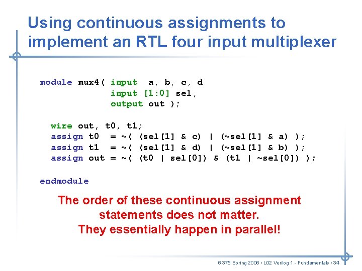
Using continuous assignments to implement an RTL four input multiplexer module mux 4( input a, b, c, d input [1: 0] sel, output out ); wire out, t 0, t 1; assign t 0 out = ~( (sel[1] (t 0 | sel[0]) & c) |&(~sel[1] (t 1 | ~sel[0]) & a) ); ); assign t 1 = ~( (sel[1] & d) | (~sel[1] & b) ); assign out t 0 = ~( (t 0 (sel[1] | sel[0]) & c) |&(~sel[1] (t 1 | ~sel[0]) & a) ); ); endmodule The order of these continuous assignment statements does not matter. They essentially happen in parallel! 6. 375 Spring 2006 • L 02 Verilog 1 - Fundamentals • 34
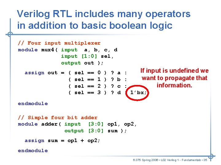
Verilog RTL includes many operators in addition to basic boolean logic // Four input multiplexer module mux 4( input a, b, c, d input [1: 0] sel, output out ); assign out = ( ( sel sel == == 0 1 2 3 ) ) ? ? a b c d If input is undefined we : want to propagate that : information. : : 1’bx; endmodule // Simple four bit adder module adder( input [3: 0] op 1, op 2, output [3: 0] sum ); assign sum = op 1 + op 2; endmodule 6. 375 Spring 2006 • L 02 Verilog 1 - Fundamentals • 35
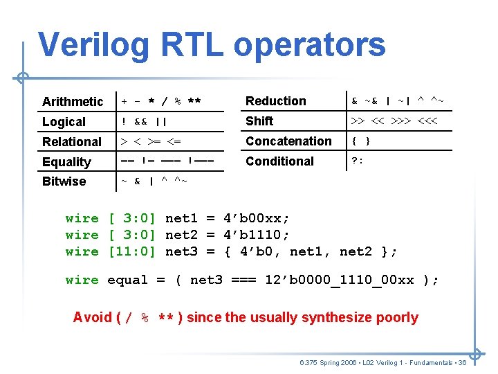
Verilog RTL operators Arithmetic + - * / % ** Reduction & ~& | ~| ^ ^~ Logical ! && || Shift >> << >>> <<< Relational > < >= <= Concatenation { } Equality == != === !=== Conditional ? : Bitwise ~ & | ^ ^~ wire [ 3: 0] net 1 = 4’b 00 xx; wire [ 3: 0] net 2 = 4’b 1110; wire [11: 0] net 3 = { 4’b 0, net 1, net 2 }; wire equal = ( net 3 === 12’b 0000_1110_00 xx ); Avoid ( / % ** ) since the usually synthesize poorly 6. 375 Spring 2006 • L 02 Verilog 1 - Fundamentals • 36
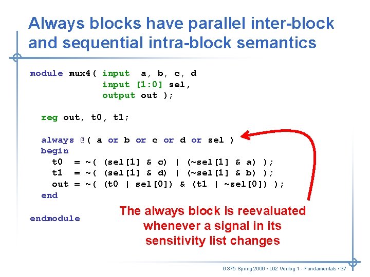
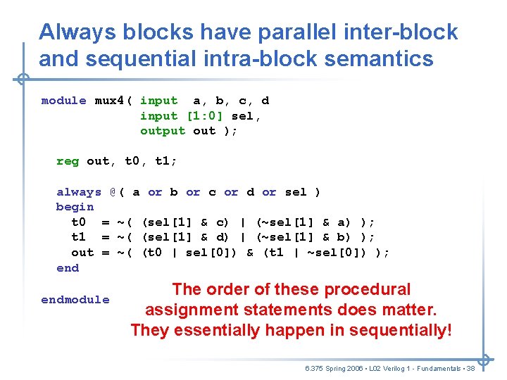
Always blocks have parallel inter-block and sequential intra-block semantics module mux 4( input a, b, c, d input [1: 0] sel, output out ); reg out, t 0, t 1; always @( a or b or c or d or sel ) begin t 0 = ~( (sel[1] & c) | (~sel[1] & a) ); t 1 = ~( (sel[1] & d) | (~sel[1] & b) ); out = ~( (t 0 | sel[0]) & (t 1 | ~sel[0]) ); endmodule The always block is reevaluated whenever a signal in its sensitivity list changes 6. 375 Spring 2006 • L 02 Verilog 1 - Fundamentals • 37
Always blocks have parallel inter-block and sequential intra-block semantics module mux 4( input a, b, c, d input [1: 0] sel, output out ); reg out, t 0, t 1; always @( a or b or c or d or sel ) begin t 0 = ~( (sel[1] & c) | (~sel[1] & a) ); t 1 = ~( (sel[1] & d) | (~sel[1] & b) ); out = ~( (t 0 | sel[0]) & (t 1 | ~sel[0]) ); endmodule The order of these procedural assignment statements does matter. They essentially happen in sequentially! 6. 375 Spring 2006 • L 02 Verilog 1 - Fundamentals • 38
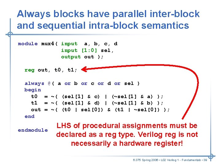
Always blocks have parallel inter-block and sequential intra-block semantics module mux 4( input a, b, c, d input [1: 0] sel, output out ); reg out, t 0, t 1; always @( a or b or c or d or sel ) begin t 0 = ~( (sel[1] & c) | (~sel[1] & a) ); t 1 = ~( (sel[1] & d) | (~sel[1] & b) ); out = ~( (t 0 | sel[0]) & (t 1 | ~sel[0]) ); endmodule LHS of procedural assignments must be declared as a reg type. Verilog reg is not necessarily a hardware register! 6. 375 Spring 2006 • L 02 Verilog 1 - Fundamentals • 39
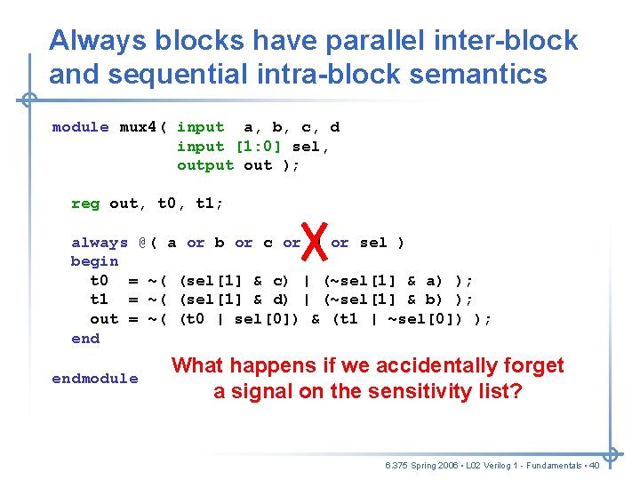
Always blocks have parallel inter-block and sequential intra-block semantics module mux 4( input a, b, c, d input [1: 0] sel, output out ); reg out, t 0, t 1; always @( a or b or c or d or sel ) begin t 0 = ~( (sel[1] & c) | (~sel[1] & a) ); t 1 = ~( (sel[1] & d) | (~sel[1] & b) ); out = ~( (t 0 | sel[0]) & (t 1 | ~sel[0]) ); endmodule What happens if we accidentally forget a signal on the sensitivity list? 6. 375 Spring 2006 • L 02 Verilog 1 - Fundamentals • 40
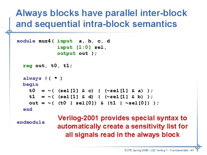
Always blocks have parallel inter-block and sequential intra-block semantics module mux 4( input a, b, c, d input [1: 0] sel, output out ); reg out, t 0, t 1; always @( * ) begin t 0 = ~( (sel[1] & c) | (~sel[1] & a) ); t 1 = ~( (sel[1] & d) | (~sel[1] & b) ); out = ~( (t 0 | sel[0]) & (t 1 | ~sel[0]) ); endmodule Verilog-2001 provides special syntax to automatically create a sensitivity list for all signals read in the always block 6. 375 Spring 2006 • L 02 Verilog 1 - Fundamentals • 41
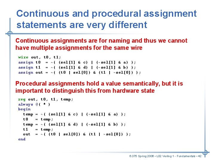
Continuous and procedural assignment statements are very different Continuous assignments are for naming and thus we cannot have multiple assignments for the same wire out, t 0, t 1; assign t 0 = ~( (sel[1] & c) | (~sel[1] & a) ); assign t 1 = ~( (sel[1] & d) | (~sel[1] & b) ); assign out = ~( (t 0 | sel[0]) & (t 1 | ~sel[0]) ); Procedural assignments hold a value semantically, but it is important to distinguish this from hardware state reg out, t 0, t 1, temp; always @( * ) begin temp = ~( (sel[1] & c) | (~sel[1] & a) ); t 0 = temp; temp = ~( (sel[1] & d) | (~sel[1] & b) ); t 1 = temp; out = ~( (t 0 | sel[0]) & (t 1 | ~sel[0]) ); end 6. 375 Spring 2006 • L 02 Verilog 1 - Fundamentals • 42
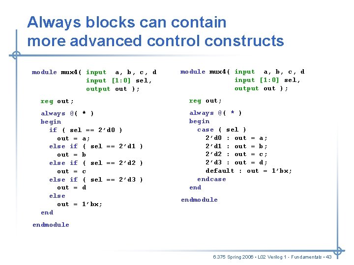
Always blocks can contain more advanced control constructs module mux 4( input a, b, c, d input [1: 0] sel, output out ); reg out; always @( * ) begin if ( sel == 2’d 0 out = a; else if ( sel == out = b else if ( sel == out = c else if ( sel == out = d else out = 1’bx; end always @( * ) begin case ( sel ) 2’d 0 : out = a; 2’d 1 : out = b; 2’d 2 : out = c; 2’d 3 : out = d; default : out = 1’bx; endcase end ) 2’d 1 ) 2’d 2 ) 2’d 3 ) endmodule 6. 375 Spring 2006 • L 02 Verilog 1 - Fundamentals • 43
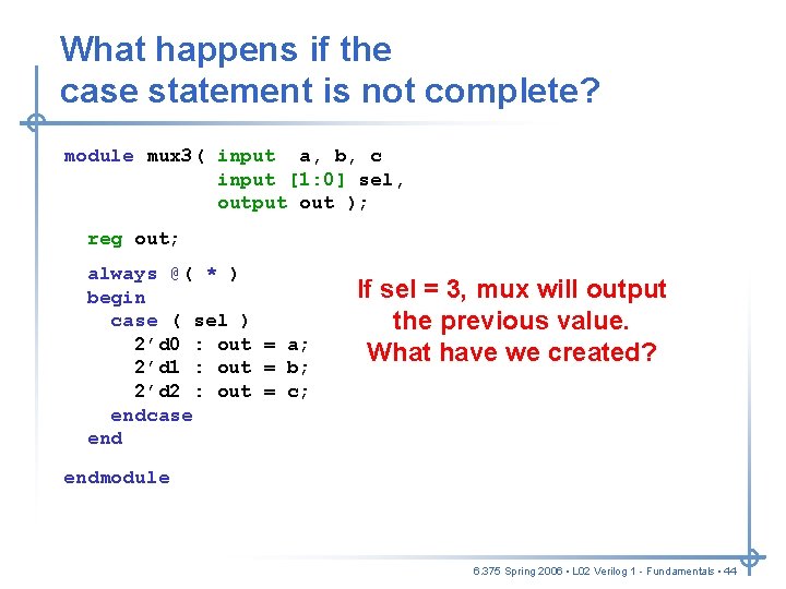
What happens if the case statement is not complete? module mux 3( input a, b, c input [1: 0] sel, output out ); reg out; always @( * ) begin case ( sel ) 2’d 0 : out = a; 2’d 1 : out = b; 2’d 2 : out = c; endcase end If sel = 3, mux will output the previous value. What have we created? endmodule 6. 375 Spring 2006 • L 02 Verilog 1 - Fundamentals • 44
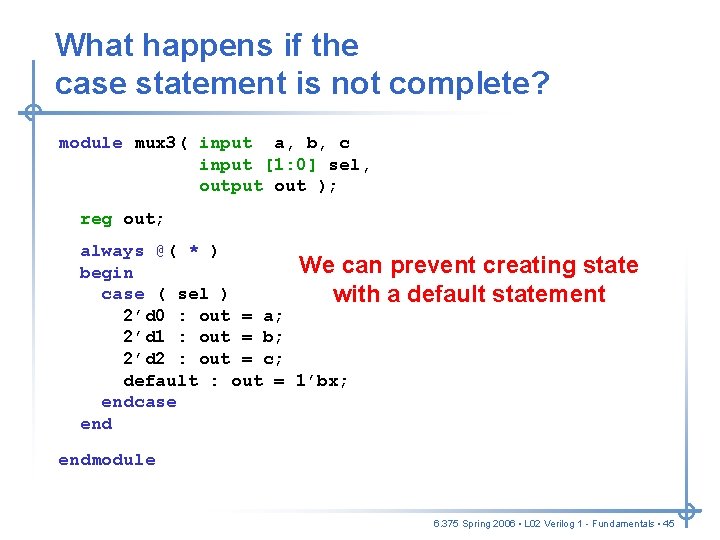
What happens if the case statement is not complete? module mux 3( input a, b, c input [1: 0] sel, output out ); reg out; always @( * ) We can prevent creating state begin case ( sel ) with a default statement 2’d 0 : out = a; 2’d 1 : out = b; 2’d 2 : out = c; default : out = 1’bx; endcase endmodule 6. 375 Spring 2006 • L 02 Verilog 1 - Fundamentals • 45
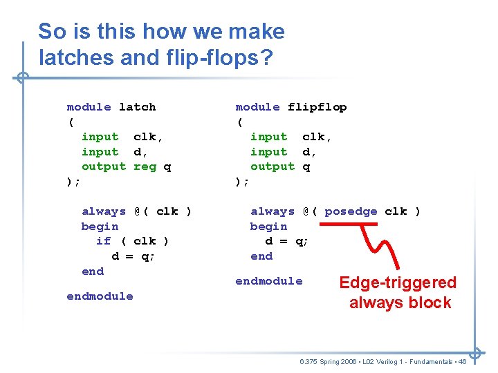
So is this how we make latches and flip-flops? module latch ( input clk, input d, output reg q ); always @( clk ) begin if ( clk ) d = q; endmodule flipflop ( input clk, input d, output q ); always @( posedge clk ) begin d = q; endmodule Edge-triggered always block 6. 375 Spring 2006 • L 02 Verilog 1 - Fundamentals • 46
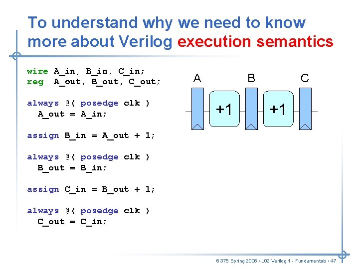
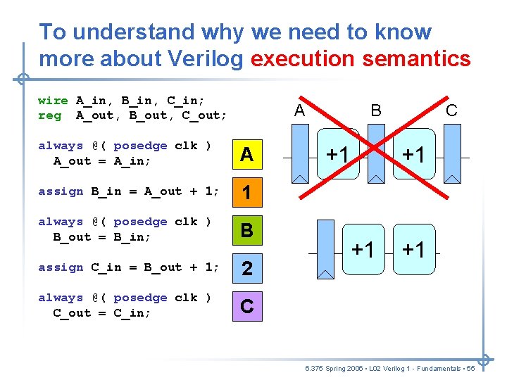
To understand why we need to know more about Verilog execution semantics wire A_in, B_in, C_in; reg A_out, B_out, C_out; always @( posedge clk ) A_out = A_in; A B +1 C +1 assign B_in = A_out + 1; always @( posedge clk ) B_out = B_in; assign C_in = B_out + 1; always @( posedge clk ) C_out = C_in; 6. 375 Spring 2006 • L 02 Verilog 1 - Fundamentals • 47
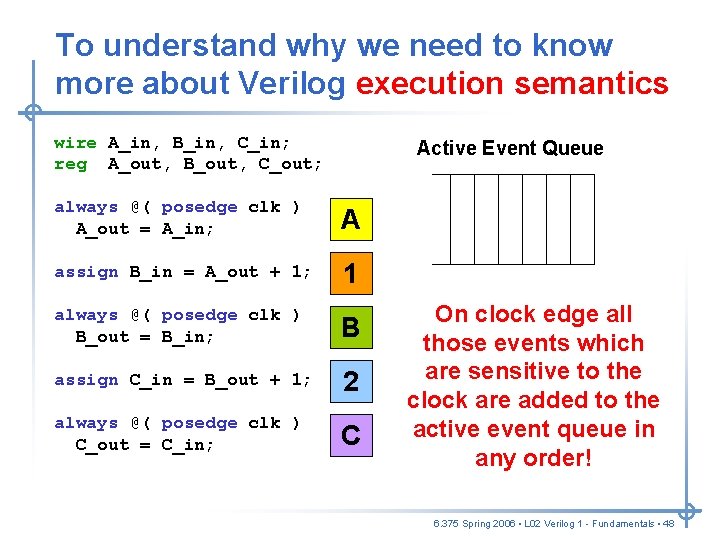
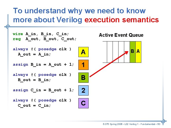
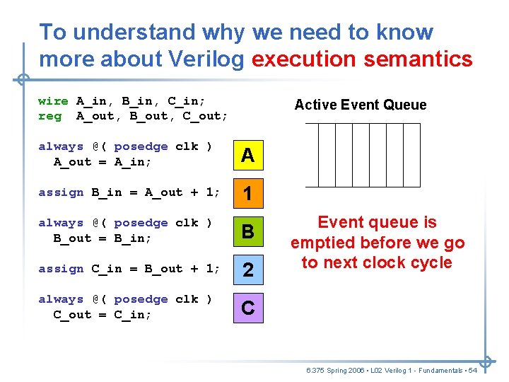
To understand why we need to know more about Verilog execution semantics wire A_in, B_in, C_in; reg A_out, B_out, C_out; Active Event Queue always @( posedge clk ) A_out = A_in; A assign B_in = A_out + 1; 1 always @( posedge clk ) B_out = B_in; B assign C_in = B_out + 1; 2 always @( posedge clk ) C_out = C_in; C On clock edge all those events which are sensitive to the clock are added to the active event queue in any order! 6. 375 Spring 2006 • L 02 Verilog 1 - Fundamentals • 48
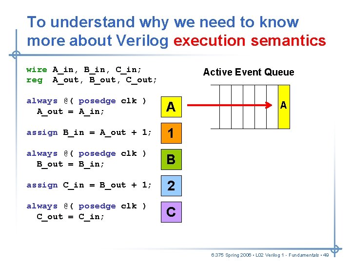
To understand why we need to know more about Verilog execution semantics wire A_in, B_in, C_in; reg A_out, B_out, C_out; Active Event Queue always @( posedge clk ) A_out = A_in; A assign B_in = A_out + 1; 1 always @( posedge clk ) B_out = B_in; B assign C_in = B_out + 1; 2 always @( posedge clk ) C_out = C_in; C A 6. 375 Spring 2006 • L 02 Verilog 1 - Fundamentals • 49
To understand why we need to know more about Verilog execution semantics wire A_in, B_in, C_in; reg A_out, B_out, C_out; Active Event Queue always @( posedge clk ) A_out = A_in; A assign B_in = A_out + 1; 1 always @( posedge clk ) B_out = B_in; B assign C_in = B_out + 1; 2 always @( posedge clk ) C_out = C_in; C B A 6. 375 Spring 2006 • L 02 Verilog 1 - Fundamentals • 50
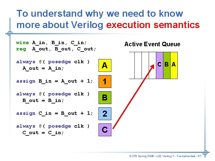
To understand why we need to know more about Verilog execution semantics wire A_in, B_in, C_in; reg A_out, B_out, C_out; Active Event Queue always @( posedge clk ) A_out = A_in; A assign B_in = A_out + 1; 1 always @( posedge clk ) B_out = B_in; B assign C_in = B_out + 1; 2 always @( posedge clk ) C_out = C_in; C C B A 6. 375 Spring 2006 • L 02 Verilog 1 - Fundamentals • 51
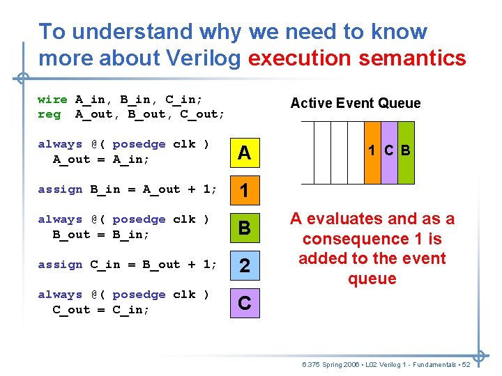
To understand why we need to know more about Verilog execution semantics wire A_in, B_in, C_in; reg A_out, B_out, C_out; Active Event Queue always @( posedge clk ) A_out = A_in; A assign B_in = A_out + 1; 1 always @( posedge clk ) B_out = B_in; B assign C_in = B_out + 1; 2 always @( posedge clk ) C_out = C_in; C C 1 C B B A A evaluates and as a consequence 1 is added to the event queue 6. 375 Spring 2006 • L 02 Verilog 1 - Fundamentals • 52
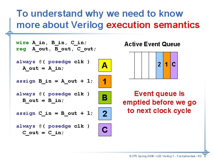
To understand why we need to know more about Verilog execution semantics wire A_in, B_in, C_in; reg A_out, B_out, C_out; Active Event Queue always @( posedge clk ) A_out = A_in; A assign B_in = A_out + 1; 1 always @( posedge clk ) B_out = B_in; B assign C_in = B_out + 1; 2 always @( posedge clk ) C_out = C_in; C C 1 C 2 1 B B evaluates Event queue andis as a emptied consequence before we 2 isgo to added nextto clock the event cycle queue 6. 375 Spring 2006 • L 02 Verilog 1 - Fundamentals • 53
To understand why we need to know more about Verilog execution semantics wire A_in, B_in, C_in; reg A_out, B_out, C_out; Active Event Queue always @( posedge clk ) A_out = A_in; A assign B_in = A_out + 1; 1 always @( posedge clk ) B_out = B_in; B assign C_in = B_out + 1; 2 always @( posedge clk ) C_out = C_in; C Event queue is emptied before we go to next clock cycle 6. 375 Spring 2006 • L 02 Verilog 1 - Fundamentals • 54
To understand why we need to know more about Verilog execution semantics wire A_in, B_in, C_in; reg A_out, B_out, C_out; A always @( posedge clk ) A_out = A_in; A assign B_in = A_out + 1; 1 always @( posedge clk ) B_out = B_in; B assign C_in = B_out + 1; 2 always @( posedge clk ) C_out = C_in; C B +1 +1 C +1 +1 6. 375 Spring 2006 • L 02 Verilog 1 - Fundamentals • 55
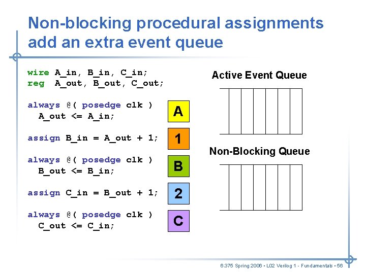
Non-blocking procedural assignments add an extra event queue wire A_in, B_in, C_in; reg A_out, B_out, C_out; Active Event Queue always @( posedge clk ) A_out <= A_in; A assign B_in = A_out + 1; 1 always @( posedge clk ) B_out <= B_in; B assign C_in = B_out + 1; 2 always @( posedge clk ) C_out <= C_in; C 2 1 C B A R R R Non-Blocking Queue C B A L L L 6. 375 Spring 2006 • L 02 Verilog 1 - Fundamentals • 56
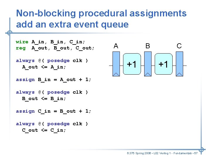
Non-blocking procedural assignments add an extra event queue wire A_in, B_in, C_in; reg A_out, B_out, C_out; always @( posedge clk ) A_out <= A_in; A B +1 C +1 assign B_in = A_out + 1; always @( posedge clk ) B_out <= B_in; assign C_in = B_out + 1; always @( posedge clk ) C_out <= C_in; 6. 375 Spring 2006 • L 02 Verilog 1 - Fundamentals • 57
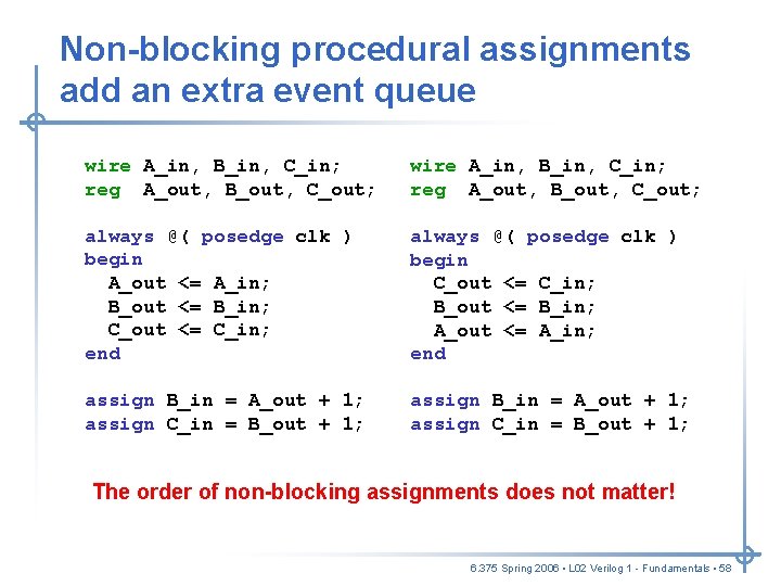
Non-blocking procedural assignments add an extra event queue wire A_in, B_in, C_in; reg A_out, B_out, C_out; always @( posedge clk ) begin A_out <= A_in; B_out <= B_in; C_out <= C_in; end always @( posedge clk ) begin C_out <= C_in; B_out <= B_in; A_out <= A_in; end assign B_in = A_out + 1; assign C_in = B_out + 1; The order of non-blocking assignments does not matter! 6. 375 Spring 2006 • L 02 Verilog 1 - Fundamentals • 58
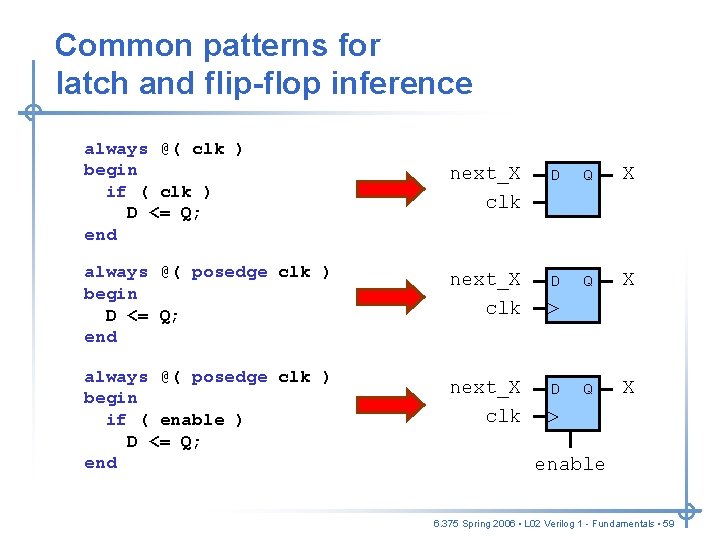
Common patterns for latch and flip-flop inference always @( clk ) begin if ( clk ) D <= Q; end always @( posedge clk ) begin if ( enable ) D <= Q; end next_X clk D Q X enable 6. 375 Spring 2006 • L 02 Verilog 1 - Fundamentals • 59
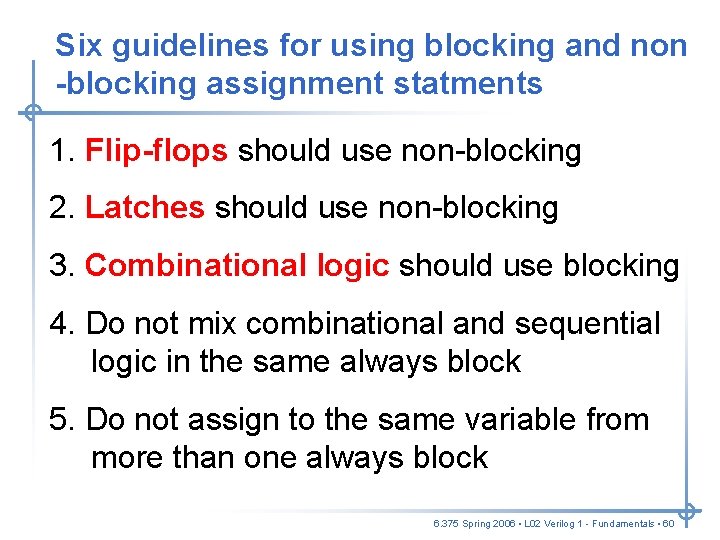
Six guidelines for using blocking and non -blocking assignment statments 1. Flip-flops should use non-blocking 2. Latches should use non-blocking 3. Combinational logic should use blocking 4. Do not mix combinational and sequential logic in the same always block 5. Do not assign to the same variable from more than one always block 6. 375 Spring 2006 • L 02 Verilog 1 - Fundamentals • 60
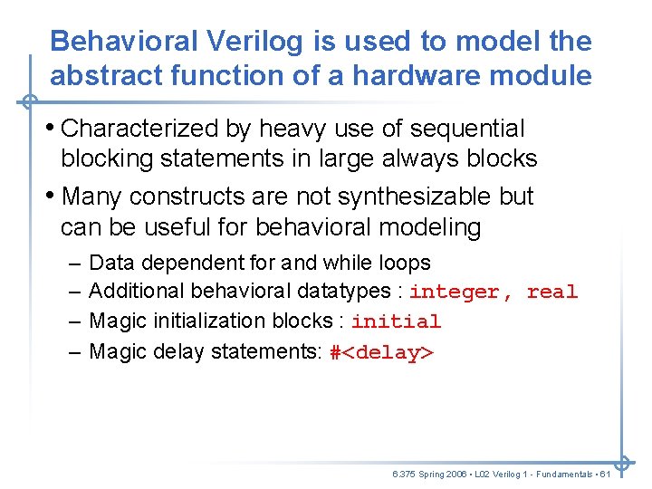
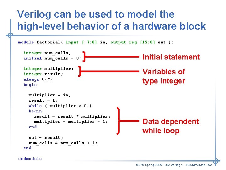
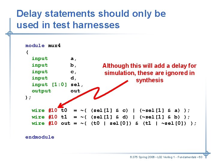
Behavioral Verilog is used to model the abstract function of a hardware module • Characterized by heavy use of sequential blocking statements in large always blocks • Many constructs are not synthesizable but can be useful for behavioral modeling – – Data dependent for and while loops Additional behavioral datatypes : integer, real Magic initialization blocks : initial Magic delay statements: #<delay> 6. 375 Spring 2006 • L 02 Verilog 1 - Fundamentals • 61
Verilog can be used to model the high-level behavior of a hardware block module factorial( input [ 7: 0] in, output reg [15: 0] out ); integer num_calls; initial num_calls = 0; Initial statement integer multiplier; integer result; always @(*) begin Variables of type integer multiplier = in; result = 1; while ( multiplier > 0 ) begin result = result * multiplier; multiplier = multiplier - 1; end Data dependent while loop out = result; num_calls = num_calls + 1; endmodule 6. 375 Spring 2006 • L 02 Verilog 1 - Fundamentals • 62
Delay statements should only be used in test harnesses module mux 4 ( input input [1: 0] output ); a, b, c, d, sel, out Although this will add a delay for simulation, these are ignored in synthesis wire #10 t 0 = ~( (sel[1] & c) | (~sel[1] & a) ); wire #10 t 1 = ~( (sel[1] & d) | (~sel[1] & b) ); wire #10 out = ~( (t 0 | sel[0]) & (t 1 | ~sel[0]) ); endmodule 6. 375 Spring 2006 • L 02 Verilog 1 - Fundamentals • 63
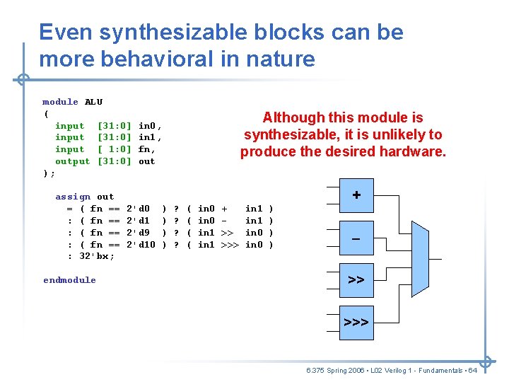
Even synthesizable blocks can be more behavioral in nature module ALU ( input [31: 0] input [ 1: 0] output [31: 0] ); assign out = ( fn == : 32'bx; endmodule Although this module is synthesizable, it is unlikely to produce the desired hardware. in 0, in 1, fn, out 2'd 0 2'd 1 2'd 9 2'd 10 ) ) ? ? ( ( in 0 in 1 + >> >>> in 1 in 0 ) ) + – >> >>> 6. 375 Spring 2006 • L 02 Verilog 1 - Fundamentals • 64
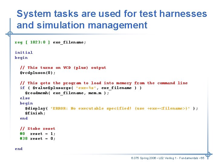
System tasks are used for test harnesses and simulation management reg [ 1023: 0 ] exe_filename; initial begin // This turns on VCD (plus) output $vcdpluson(0); // This gets the program to load into memory from the command line if ( $value$plusargs( "exe=%s", exe_filename ) ) $readmemh( exe_filename, mem. m ); else begin $display( "ERROR: No executable specified! (use +exe=<filename>)" ); $finish; end // Stobe reset #0 reset = 1; #38 reset = 0; end 6. 375 Spring 2006 • L 02 Verilog 1 - Fundamentals • 65
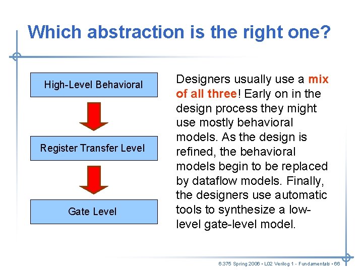
Which abstraction is the right one? High-Level Behavioral Register Transfer Level Gate Level Designers usually use a mix of all three! Early on in the design process they might use mostly behavioral models. As the design is refined, the behavioral models begin to be replaced by dataflow models. Finally, the designers use automatic tools to synthesize a lowlevel gate-level model. 6. 375 Spring 2006 • L 02 Verilog 1 - Fundamentals • 66
Take away points • Structural Verilog enables us to describe a hardware schematic textually • Verilog can model hardware at three levels of abstraction: gate level, register transfer level, and behavioral • Understanding the Verilog execution semantics is critical for understanding blocking + non-blocking assignments • Designers must have the hardware they are trying to create in mind when they write their Verilog Next Lecture: We will use a simple SMIPS processor to illustrate many of concepts introduced today. 6. 375 Spring 2006 • L 02 Verilog 1 - Fundamentals • 67