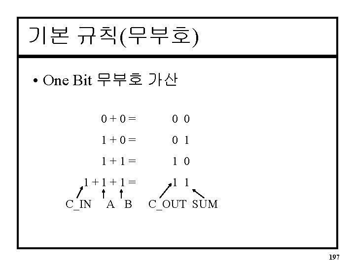
1 Carry to next 1 1 1 0


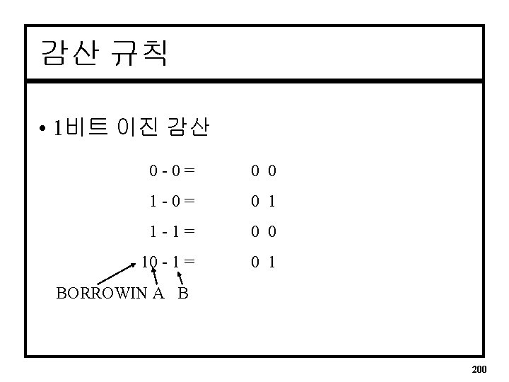
 -1001 100 1 Borrow")

 57")
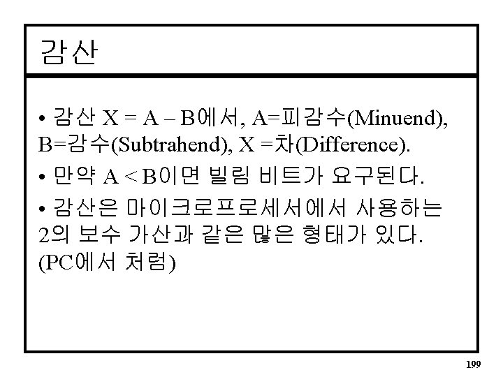
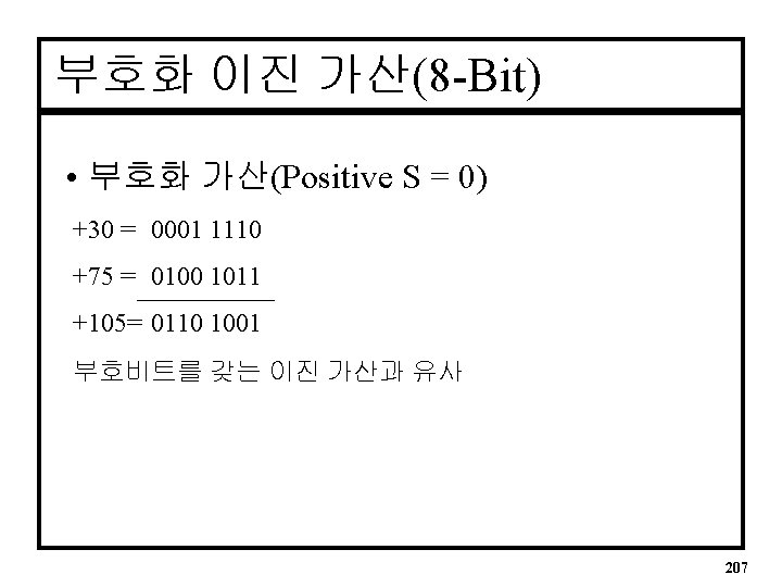
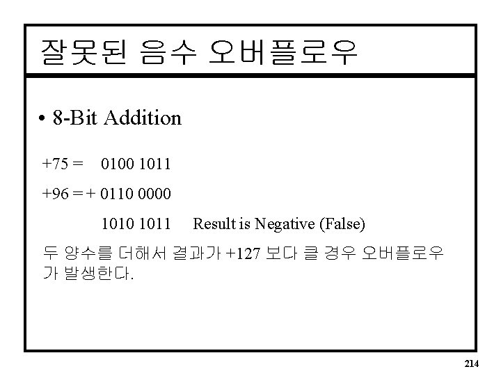
 연산에서 사용 +57 = 00111001 +72 = 01001000 -57")


 +65 = 0100 0001")
10 = 0100 1001 1000 0111 (BCD) • (84)10 = 1000")


 MSB in the Gray code is")
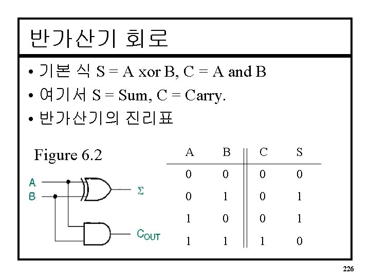
 A 1 A S 0 CI")

 Ex) 0101 -0011 2’s comp. of “ 0011” 0011 1100(1’s) +1")
 241")

 1. 2. 3. 4. 전가산기에 대한 독립적인 컴포넌트 파일(full_adder. vhd)은 컴파일")
 BEGIN component instantiation(s); other statements; END arch_name; -- component declaration statement")
 -- component instantiation statement template __instance_name: __component_name GENERIC MAP (__parameter_name =>")

 • 병렬 가산기를 위해 사용된 전가산기 컴포넌트")
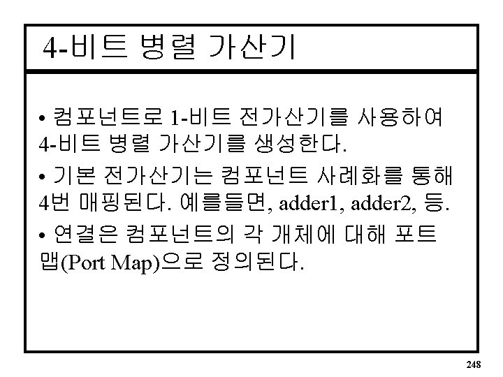
 • Mapping Type of Architecture BEGIN -- 4 component")
 • Remaining part of the Architecture adder 4: full_adder")

 • 생성문은 하드웨어의 반복되는 부분을 생성하기 위해 사용된다. -- GENERATE statement template")
 -- COMPONENT declaration COMPONENT full_adder -- Previous FA Design File PORT( a,")
 254")
 259")


 ARCHITECTURE adder OF bcd_add IS -- Component declaration COMPONENT add 4")
 BEGIN -- Instantiate 4 -bit adder (binary sum) add_bin: add 4")
 BCD 가산기 Fig. 6. 27 4 ½ Digit BCD Adder 264")

 - Normal Device : EPM 7032 SLC 44 -5 267")


- Slides: 78
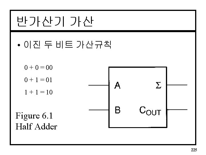
이진 가산 예 • 이진 가산 1 Carry to next 1 1 1 0 0 1 0 1 1 1 0 + 1 0 1 0 0 1 1 1 0 0 0 1 Carry Out Bit 198
이진 감산 예 • 빌림이 있는 이진 감산 1110 110(10) -1001 100 1 Borrow Stage 010 1 10000 0111(10) - 101 10 1 Borrow ripples to LSB 0101 1 201
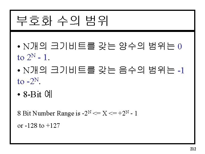
참 크기 형태 • 5 Bit Numbers/ Negative = S=1 +25 = 011001 sign bit = MSB = S = 0 -25 = 111001 Same as +25 with S=1 -12 = 101100 +12 = 001100 True magnitude 204
1의 보수 형태 • 8 -Bit 1’s Complement (Negative = S = 1) 57 = 0011 1001 -57 = 1100 0110 All Bits Inverted 72 = 0100 1000 -72 = 1011 0111 205
2의 보수 형태 • MPU(PC) 연산에서 사용 +57 = 00111001 +72 = 01001000 -57 = 11000110 -72 = 10110111 + 1 10111111 10111000 206
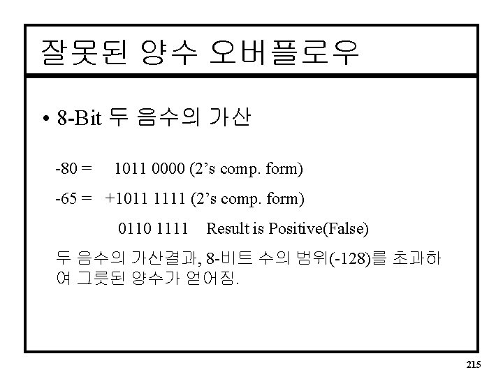
1의 보수에 의한 감산 • 1의 보수를 더하고 캐리를 더함 +80 = 0101 0000 (+80) = 0101 0000 -65 => 0100 0001 (+65) = 1011 1110 (1’s Comp 65) 10000 1110 + 1(end-around carry) 0000 1111 (+15) ‘End around carry’ 가산방법을 사용 208
2의 보수 감산 • 피감수에 2의 보수를 가산 +80 = 0101 0000 +65 = 0100 0001 +1011 1111 -65 = 1011 1110 +1 1 0000 1111 Discard Carry Bit from result 209
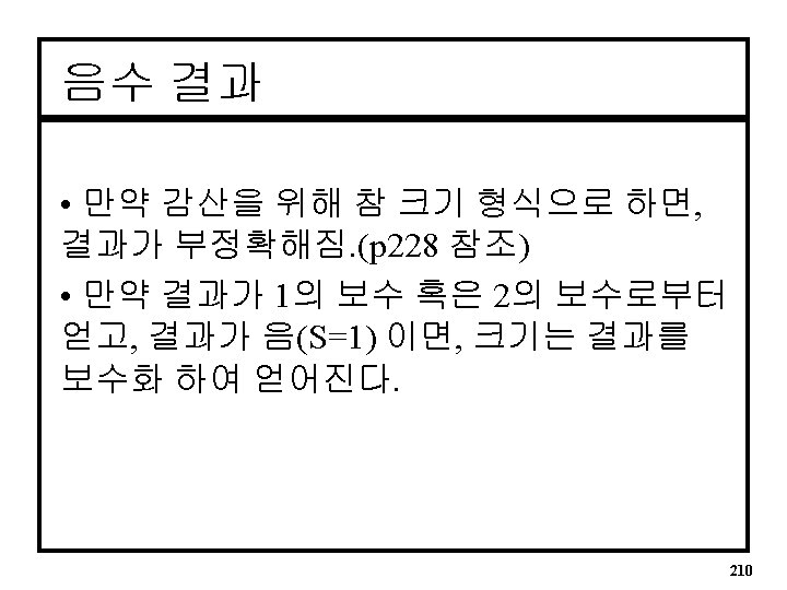
음수 결과 예 • 2’s Complement Negative Result (65 -80) +65 = 0100 0001 -80 = 1011 0000 (2’s C. ) +1011 0000 결과의 부호비트가 1이면 그것은 음수이고 2의 보수 형태이다. 1111 0001 Invert 0000 1110 Add 1 + 1 Final Result = -15 0000 1111 = 15(Neg. ) 211
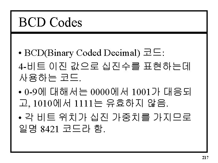
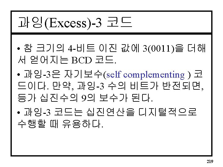
BCD 예 • (4987)10 = 0100 1001 1000 0111 (BCD) • (84)10 = 1000 0100 • 각 자리는 4 -Bit 이진 그룹이다. 218
Excess-3 예 • 3 = 0011 + 0011 = 0110 = 6 in E-3. • 1 = 0001 + 0011 = 0100 = 4 in E-3 • 9’s Complement of 1(0100 in E-3) = (9 - 1) = 8 • If we take 1’s complement for 1011(8 in E-3 code). => 0100 • Self Complement : /(E-3 code) = 9’s 보수) 220
Gray Code 그레이코드 비 가중치 코드고 연산코드가 아님; 즉, 비트 위치마다 가중 값이 없다. 그레이 코드의 중요한 특징은 한 코드 수와 다음 코드 수 사이에는 단지 한 비트만 변한다. Shaft position encoder(응용) 4 -bit Gray code Decimal Binary Gray code 0 1 2 3 4 5 6 7 0000 0001 0010 0011 0100 0101 0110 0111 0000 0001 0010 0111 0100 8 9 10 11 12 13 14 15 1000 1001 1010 1011 1100 1101 1110 1111 1100 1101 1110 1011 1000 221
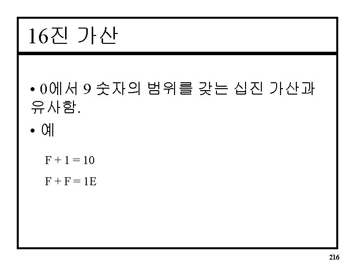
그레이코드 변환 Binary-to-Gray code conversion 1. 2. Ex) MSB in the Gray code is the same as MSB in the binary number. Going from left to right, add each adjacent pair of binary code bits to get the next Gray code bit. Discard carries. 1 0 1 1 0 (Binary) 1 1 1 0 1 (Gray) Gray-to-Binary code conversion (For 4 -bit code g 3 = b 3 g 2 = b 3 xor b 2 g 1 = b 2 xor b 1 g 0 = b 1 xor b 0) 1. 2. MSB in the Binary code is the same as MSB in the Gray code. Add each binary code bit generated to the Gray code bit in the next adjacent position. Discard carries. (For 4 -bit code Ex) 1 1 0 1 1 (Gray) b 3 = g 3 b 2 = b 3 xor g 2 b 1 = b 2 xor g 1 1 0 0 1 0 (Binary) b 0 = b 1 xor g 0) 222
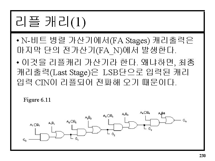
병렬 가산기 • N-Bit Multiple Adder (FA Stages) A 1 A S 0 CI CO B 1 B A 2 B 2 S 1 A S CI CO B AN A CI BN B S 2 SN 229
4 -bit Fast Carry Circuit Fig. 6. 12 234
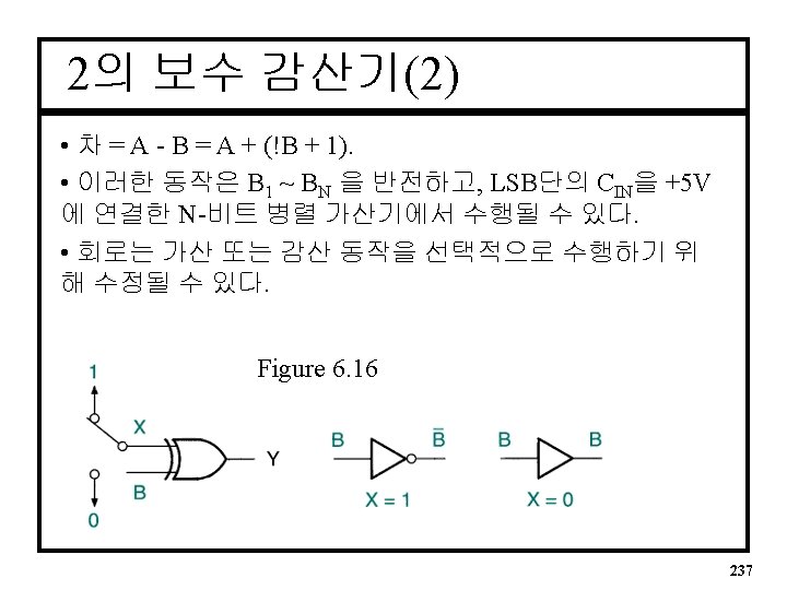
2의 보수 감산기(1) Ex) 0101 -0011 2’s comp. of “ 0011” 0011 1100(1’s) +1 1101 Fig. 6. 14 0101(+5) + 1101(-3) 1 0010(+2) discard carry 236
Figure 6. 13 (4 -bit parallel adder with ripple carry) 241
전가산기 VHDL • 기본적인 전가산기 ENTITY full_adder IS PORT( a, b, c_in : IN BIT; c_out, sum : OUT BIT); END full_adder; ARCHITECTURE adder OF full_adder IS BEGIN C_OUT <= ((a XOR b) AND C_IN) OR (a AND b); SUM <= (a XOR b) XOR c_in; END adder; 242
계층적 VHDL 설계과정(1) 1. 2. 3. 4. 전가산기에 대한 독립적인 컴포넌트 파일(full_adder. vhd)은 컴파일 러가 발견할 수 있는 폴더내에 저장되어야 한다. (말하자면, 라이브 러리 경로상에) A component declaration statement 은 설계 계층의 최상위 레벨의 파 일에 있어야 한다. A component instantiation statement 은 전가산기 컴포넌트의 각 사례 에 대한 것이다. 컴포넌트를 사용한 설계 엔티티의 일반적인 형식은: ENTITY entity_name IS PORT ( input and output definitions); END entity_name; ARCHITECTURE arch_name OF entity_name IS component declaration(s); signal declaration(s); 243
계층적 VHDL 설계과정(2) BEGIN component instantiation(s); other statements; END arch_name; -- component declaration statement template COMPONENT __component_name GENERIC(__parameter_name : string : = __default_value; __parameter_name : integer : = __default_value); PORT( __input_name, __input_name : IN STD_LOGIC; __bidir_name, __bidir_name : INOUT STD_LOGIC; __output_name, __output_name : OUT STD_LOGIC); END COMPONENT; 244
계층적 VHDL 설계과정(3) -- component instantiation statement template __instance_name: __component_name GENERIC MAP (__parameter_name => __parameter_value , __parameter_name => __parameter_value) PORT MAP (__component_port => __connect_port, __component_port => __connect_port); Label(instance_name)는 컴포넌트 사례화문에서는 반드시 사용해야 한다. 245
4 -비트 병렬 이진 가산기 Entity • 4 -비트 병렬 가산기 I/O Pins ENTITY add 4 par IS PORT( C 0 : IN BIT; A, B : IN BIT_VECTOR(4 downto 1); C 4 : OUT BIT; SUM : OUT BIT_VECTOR(4 downto 1)); END add 4 par; ARCHITECTURE adder OF add 4 par IS 246
4 -비트 병렬 가산기 컴포넌트(1 -Bit FA) • 병렬 가산기를 위해 사용된 전가산기 컴포넌트 -- component declaration statement COMPONENT full-adder PORT( a, b, c_in c_out, sum -- Previous FA Design File : IN BIT; : OUT BIT); END COMPONENT SIGNAL c : BIT_VECTOR(3 downto 1) -- Internal signal used for intermediate carries 247
4 -비트 가산기의 Structured Architecture(1) • Mapping Type of Architecture BEGIN -- 4 component instantiation statements adder 1: full_adder 복사 개체를 구분하기위해 사용해야 함. -- This defines the first component PORT MAP (a => A(1), b=> B(1), c_in => C 0, c_out => C(1), sum=> SUM(1)); adder 2: full_adder -- This defines the second component PORT MAP (a => A(2), b=> B(2), c_in => C(1), c_out => C(2), sum=> SUM(2)): adder 3: full_adder -- This defines the third component PORT MAP (a => A(3), b=> B(3), c_in => C(2), c_out => C(3), sum=> SUM(3)); 249
4 -비트 가산기의 Structured Architecture(2) • Remaining part of the Architecture adder 4: full_adder -- This defines the fourth component PORT MAP(a => A(4), b=> B(4), c_in => C(3), c_out => C 4, sum=> SUM(4)); END adder; -- another component instantiation statement adder 1 : full_adder PORT MAP (a(1), b(1), c 0, c(1), sum(1)); adder 2 : full_adder PORT MAP (a(2), b(2), c(1), c(2), sum(2)); adder 3 : full_adder PORT MAP (a(3), b(3), c(2), c(3), sum(3)); adder 4 : full_adder PORT MAP (a(4), b(4), c(3), c 4, sum(4)); -- use the correct order originally defined 250
Generate Statement(1) • 생성문은 하드웨어의 반복되는 부분을 생성하기 위해 사용된다. -- GENERATE statement template __generate_label: FOR __index_variable IN __range GENERATE __statement; END GENERATE; -- 4 -bit adder VHDL code using generate statement ENTITY add 4 gen IS PORT( c 0 : IN BIT; a, b : IN BIT_VECTOR(4 downto 1); c 4 : OUT BIT; sum : OUT BIT_VECTOR(4 downto 1)); END add 4 gen; ARCHITECTURE adder OF add 4 gen IS 252
Generate Statement(2) -- COMPONENT declaration COMPONENT full_adder -- Previous FA Design File PORT( a, b, c_in : IN BIT; c_out, sum : OUT BIT); END COMPONENT SIGNAL c : BIT_VECTOR(4 downto 0) BEGIN c(0) <= c 0; adders : FOR i IN 1 to 4 GENERATE -- easily expandable by changing the range adder : full_adder PORT MAP (a(i), b(i), c(i-1), c(i), sum(i); END GENERATE; c 4 <= c(4); END adder; 253
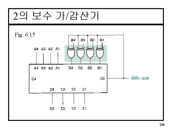
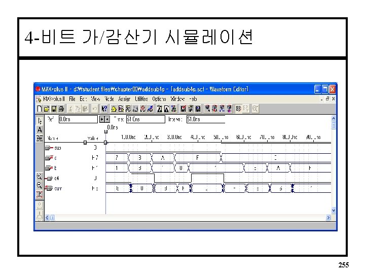
4 -bit 가/감산기(Adder/Subtractor) 254
Fig. 6. 23 BCD 가산기(1 1/2 Digit Output) 259
Fig. 6. 26 BCD 가산기 260
BCD 가산기 VHDL -- bcd_add. vhd -- BCD adder, using 2 instances of the component add 4 par -- See Figure 6. 26 for component interconnections. ENTITY bcd_add IS PORT( c 0 a, b c 4 sum END bcd_add; : IN : OUT BIT; BIT_VECTOR(4 downto 1); BIT_VECTOR(4 downto 1)); 261
BCD 가산기 VHDL(계속) ARCHITECTURE adder OF bcd_add IS -- Component declaration COMPONENT add 4 par PORT( c 0 : IN BIT; a, b : IN BIT_VECTOR(4 downto 1); c 4 : OUT BIT; sum : OUT BIT_VECTOR(4 downto 1)); END COMPONENT; SIGNAL c 4_bin : BIT; SIGNAL sum_bin : BIT_VECTOR(4 downto 1); SIGNAL a_bcd : BIT_VECTOR(4 downto 1); SIGNAL b_bcd : BIT_VECTOR(4 downto 1); SIGNAL c 0_bcd : BIT; 262
BCD 가산기 VHDL(계속) BEGIN -- Instantiate 4 -bit adder (binary sum) add_bin: add 4 par PORT MAP (c 0 => c 0, a => a, b => b, c 4 => c 4_bin, sum => sum_bin); -- Instantiate 4 -bit adder (binary-BCD converter) converter: add 4 par PORT MAP (c 0 => c 0_bcd, a =>a_bcd, b => b_bcd, sum => sum); -- Connect components c 0_bcd <= '0'; b_bcd <= sum_bin; a_bcd(4) <= '0'; a_bcd(3) <= c 4_bin or (sum_bin(4) and sum_bin(3))or (sum_bin(4) and sum_bin(2)); a_bcd(2) <= c 4_bin or (sum_bin(4) and sum_bin(3))or (sum_bin(4) and sum_bin(2)); a_bcd(1) <= '0'; c 4 <= c 4_bin or (sum_bin(4) and sum_bin(3))or (sum_bin(4) and sum_bin(2)); END adder; 263
복수자리(Multiple-Digit) BCD 가산기 Fig. 6. 27 4 ½ Digit BCD Adder 264
MAX+PLUS II 에서의 캐리 생성 - Global Project Logic Synthesis 1. FAST : A fast synthesis but a large gate size 2. NORMAL : A default synthesis 3. WYSIWYG : As synthesis a design without altering design format as possible Refer to Fig. 6. 30 & Fig. 6. 31 => We do not need to design an adder circuit to have a fast carry function (assign menu) - EXP(expander buffer) : shared logic expander in the same LAB 266
논리합성(Logic Synthesis) - Normal Device : EPM 7032 SLC 44 -5 267
논리합성 - WYSIWYG Device : EPM 7032 SLC 44 -5 268
SUMMARY I • A Hierarchical VHDL Design To use a component in a VHDL design hierarchy, we require a design entity that defines the component declaration and component instantiation statements. For example: ENTITY entity_name IS PORT ( input and output definitions); END entity_name; ARCHITECTURE arch_name OF entity_name IS component declaration(s); signal declaration(s); BEGIN component instantiation(s); other statements; END arch_name; • A Simple Port Map If all ports of a component are to be used in the same order as in the component definition in the original component design entity, the port map can simply contain the user names in the same order. For example: Adder 1 : full_adder PORT MAP ( a(1), b(1), c 0, c(1), sum(1)); 269
SUMMARY II • A Explicit Port Map If only a portion of the component ports are to be used or they are not used in the same sequence as they are declared, the port map must be more explicit. For example: adder 1: full_adder PORT MAP (a => A(1), b=> B(1), c_in => C 0, c_out => C(1), sum=> SUM(1)); • A Generate statement can be used to instantiate multiple instances of a component. For example: label: FOR index_variable IN range GENERATE statement; END GENERATE; • A Synthesis Strategy If you use ‘normal’ option, MAX+PLUS II will synthesize an adder to minimize carry delays. 270