
EEE 2243 Digital System Design Chapter 6 RTL


- Slides: 14
EEE 2243 Digital System Design Chapter 6: RTL Design by Muhazam Mustapha, April 2012
Learning Outcome • By the end of this chapter, students are expected to understand the principle of RTL design
Chapter Content • Principle of RTL Design • Example (Soda / Soft Drink Dispenser)
RTL Design
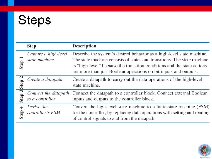
RTL Design • RTL stands for “Register Transfer Level” • RTL design is the level of digital system design that involves the datapath components and the routing of the data (information) between the components with an addition of a CENTRALIZED controller • In this chapter we will see the general steps that involves in RTL design
Steps
Soda Dispenser Example
Examples from text book • The Vahid’s and Khalil’s text book provides many examples for you to study • It is up to you read them as we won’t have enough time to cover all examples • We will only discuss the soda dispenser example from Vahid’s text book
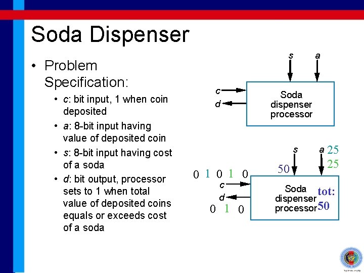
Soda Dispenser • Problem Specification: • c: bit input, 1 when coin deposited • a: 8 -bit input having value of deposited coin • s: 8 -bit input having cost of a soda • d: bit output, processor sets to 1 when total value of deposited coins equals or exceeds cost of a soda s c d Soda dispenser processor s 0 1 0 c d 0 1 0 a 50 a 25 25 Soda tot: dispenser 25 processor 50
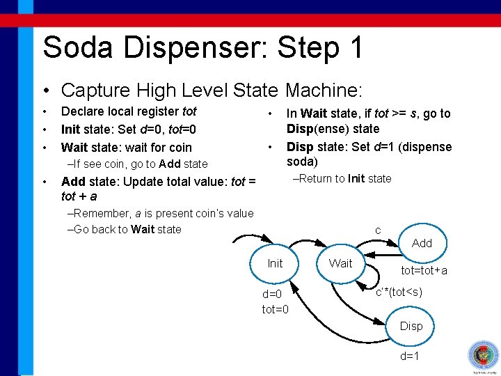
Soda Dispenser: Step 1 • Capture High Level State Machine: • • • Declare local register tot Init state: Set d=0, tot=0 Wait state: wait for coin • • –If see coin, go to Add state • In Wait state, if tot >= s, go to Disp(ense) state Disp state: Set d=1 (dispense soda) –Return to Init state Add state: Update total value: tot = tot + a –Remember, a is present coin’s value –Go back to Wait state c Add Init d=0 tot=0 Wait tot=tot+a c’*(tot<s) Disp d=1
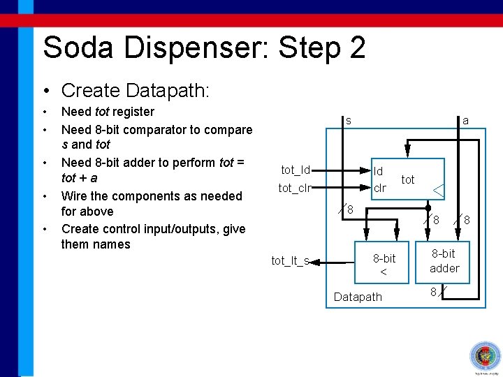
Soda Dispenser: Step 2 • Create Datapath: • • • Need tot register Need 8 -bit comparator to compare s and tot Need 8 -bit adder to perform tot = tot + a Wire the components as needed for above Create control input/outputs, give them names s tot_ld a ld clr tot_clr 8 tot_lt_s tot 8 8 -bit < Datapath 8 -bit adder 8 8
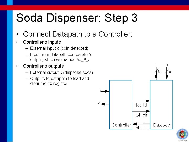
Soda Dispenser: Step 3 • Connect Datapath to a Controller: • Controller’s inputs – External input c (coin detected) – Input from datapath comparator’s output, which we named tot_lt_s • s Controller’s outputs a 8 – External output d (dispense soda) – Outputs to datapath to load and clear the tot register 8 c d tot_ld tot_clr Controller tot_lt_s Datapath
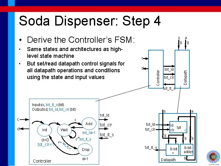
Soda Dispenser: Step 4 • Derive the Controller’s FSM: c d tot_ld tot_clr Datapath • Same states and architectures as highlevel state machine But set/read datapath control signals for all datapath operations and conditions using the state and input values Controller • s a 8 8 tot_lt_s Inputs: : c, tot_lt_s (bit) Outputs: d, tot_ld, tot_clr (bit) c d s tot_ld c Init d=0 tot_clr=1 Controller Wait Add tot_ld=1 c’* t ot_ lt_ s c’*tot_lt_s ’ Disp d=1 tot_clr tot_ld tot_clr tot_lt_s a ld tpt clr 8 tot_lt_s 8 8 -bit < Datapath 8 8 -bit adder 8
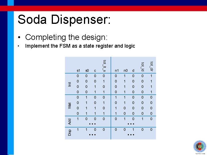
Soda Dispenser: • Completing the design: • Implement the FSM as a state register and logic