Imaging of spinal trauma Dr Vishal Sankpal Imaging

 �MRI")


 the basion (white dot) should lie within 12 mm of")


 �does not normally exceed 3 mm in adults and 5")


: � ▪ Type I: Loading fracture of the occipital")


 is an uncommon injury that involves complete disruption")

 Fractures �Generally related to axial loading �Neurologic compromise is relatively infrequent")


 An unstable JF is one in which the transverse ligament is")
 Fracture � Usually occur as a result of a lateral")
 Fracture")


 Fractures �Approximately 25% are hangman fractures, over half (58%) are odontoid")
 �Mechanism – q most common form of")


 based upon the location")


 � Minimal displacement often precludes demonstration")


 is a rare injury")


")
 � Flexion Injuries – Cla y-shoveler fracture,")


 by 16 mm")

 �burst fractures of the thoracolumbar junction and lumbar spine")

")


 and very subtle")


- Slides: 110
Imaging of spinal trauma Dr. Vishal Sankpal
Imaging modalities �Radiography �Computed Tomography (CT) �MRI
�The three-view radiography series Ø antero-posterior, Ø lateral, and Ø open mouth odontoid is still the imaging modality of choice as initial study for symptomatic patients ( as recommended by the American College of Radiology Appropriateness Criteria and the Advanced Trauma Life Support (ATLS) course of the American College of Surgeons )
�Special consideration regarding radiation dose due to the inherent radio-sensitivity of developing tissues in children compared to adults Ø Antero-posterior (AP) and lateral radiographs under the age of 4 Ø AP, lateral and open mouth radiographs from 4 to 8 years old Ø Children at 9 years of age and older are imaged with the adult protocol. This is the approximate age at which the fracture patterns revert to the adult patterns. Ø CT is reserved for those subjects in whom an abnormality is identified on radiography.
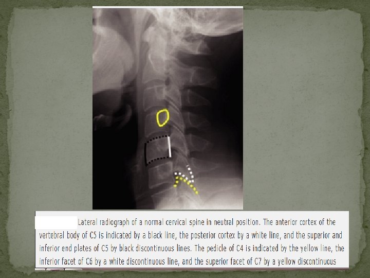
Plain Film Radiography and CT of the Cervical Spine: Normal Anatomy
ü Flexion-extension radiographs are not very helpful in the acute setting because muscle spasm in acutely injured patients precludes an adequate examination ü Flexion-extension radiographs are helpful for ensuring that minor degrees of anterolisthesis or retrolisthesis in patients with cervical spondylosis are fixed deformities
1 – Anterior spinal line 2 – Posterior spinal line 3 – Spino-laminar line
Spinolaminar line – ü Any displacement in this line may be an indication of subtle traumatic vertebral injury/dislocation. ü A line drawn through C 1 - 3 spinolaminar lines should intercept the C 2 spinolaminar line. ü A displacement of the C 2 spinolaminar line of more than 2 mm, compared with a line drawn between the spinolaminar lines of C 1 and C 3, is abnormal.
Basion dental interval (BDI) the basion (white dot) should lie within 12 mm of the top of the odontoid process The basion-axial interval (BAI) the PAL (white line) should lie within 12 mm of the basion
Basion dental interval The basion-axial interval Normal < 12 mm
� Concept initially evolved from a retrospective review of thoracolumbar spine injuries and observation of spinal instability, it has also been applied to the cervical spine. � The posterior column consists posterior ligamentous complex. � The middle column includes the posterior longitudinal ligament, posterior annulus fibrosus, and posterior wall of the vertebral body. Three-column concept of the spine � The anterior column consists of the (Denis) anterior vertebral body, anterior annulus fibrosus, and anterior longitudinal ligament.
Anterior Atlanto-dental interval (AADI) �does not normally exceed 3 mm in adults and 5 mm in children • In adults, because of maturity of the transverse atlantal ligament, the AADI remains constant in flexion and extension. • In infants and children until the age of approximately 8 years, the AADI varies in width in flexion and extension.
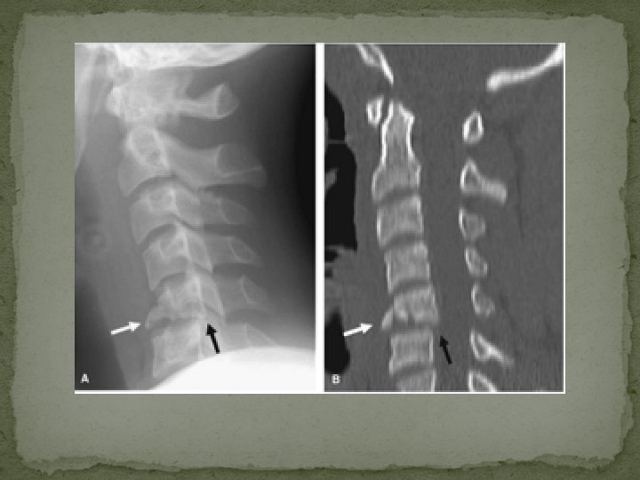
Diameter of the spinal canal ü Difficulties in making accurate measurements secondary to differences in magnification or focal spot-film distance. ü This problem can be overcome by comparing the AP width of the canal with that of the vertebral body (canal / body) ü The normal ratio of the spinal canal (white arrow) to the vertebral body (black arrow) is 0. 8 or more.
The normal atlanto-axial articulation in open- mouth odontoid view ü The lateral margins of the lateral atlanto-axial joints are symmetric and are on essentially in the same vertical plane, plus or minus 1 mm.
Cervical spine injuries - classification Location �Upper cervical injuries - include injuries to the base of the skull (including the occipital condyles or C 0), C 1, and C 2. �Lower cervical injuries (sub-axial) - include injuries from C 3 through C 7
Cervical spine injuries - classification �Vector forces – Flexion-rotation Lateral flexion Extension-rotation Vertical compression
Stability versus Instability �When assessing stability in the spinal column, the three-column theory of Denis suggests that if two columns have failed, the spinal column is unstable.
Occipital condyle fractures �OCF are rare, being found at postmortem examination in 1% to 5% of patients who had sustained trauma to the cervical spine and head �Clinical manifestations of OCF are highly variable �Not typically shown with conventional radiography
Plain film findings: Difficult diagnosis due to overlapping of the bony structures of the face, upper cervical spine, and skull base. �May be visible in open-mouth views that include the condyles �OCF are readily identified on axial or coronal reformatted CT
Anderson-Montesano classification system (for OCF): � ▪ Type I: Loading fracture of the occipital condyle, typically comminuted and in a vertical sagittal plane, but where there is no fracture displacement or associated craniocervical instability. � ▪ Type II: Skull-base fracture that propagates into one or both occipital condyles � ▪ Type III: Infero-medial avulsion fracture of the condyle by the intact alar ligament, with medial displacement of the fragment into the foramen magnum. Type III OCF are considered potentially unstable because of an avulsed alar ligament
Type III
UNSTABLE: �▪ Occipital condyle fragment displacement >5 mm �▪ Occipito-atlantal dislocation �▪ Bilateral occipital condyle fractures
Atlanto-occipital Dislocation � Atlanto-occipital dislocation (AOD) is an uncommon injury that involves complete disruption of all ligamentous relationships between the occiput and the atlas � Stability and function of the atlanto-occipital articulation are provided by the cruciate ligament, tectorial membrane, apical dental ligament, and paired alar ligaments, as well as the articular capsule ligaments � Death usually occurs immediately from stretching of the brainstem, which can result in respiratory arrest
�The lateral cervical spine radiograph is most likely to reveal the injury �Sagittal CT reconstructions or sagittal magnetic resonance imaging (MRI) can allow for the diagnosis when plain radiography is inconclusive. Atlanto-occipital Distraction • >12 mm Basion Dental distance • Separated occipital condyle and superior surface of C 1
Atlas (C 1) Fractures �Generally related to axial loading �Neurologic compromise is relatively infrequent with fractures of the C 1 ring, presumably because the axial compression mechanism results in a burst configuration with expansion of the spinal canal Ø Jefferson Fracture Ø Lateral Mass (C 1) Fracture Ø Isolated Fractures of C 1
Jefferson Fracture � Classically, a four-point injury with fractures occurring at the junctions of the anterior and posterior arches with the lateral masses, the weakest structural portions of the atlas � Most commonly there are two fractures in the posterior arch (one on each side) and a single fracture in the anterior arch, off the midline � Mechanism - A JF is created by sudden and direct axial loading on the vertex. The lateral articular masses of the atlas become compressed between the occipital condyles and the superior articular facets of the axis. By its nature, this is a decompressive injury because the bony fragments are displaced radially away from the neural structures
Jefferson Fracture Most common
Plain film findings: Open-mouth odontoid view ▪ Bilateral offset or spreading of the lateral articular masses of C 1 in relation to the apposing articular surfaces of C 2 ▪ It is often difficult to visualize the lines of fracture per se Lateral view: (difficult diagnosis on the lateral view) ▪ Increase in the atlanto-axial distance (>3 mm) ▪ Anterior or posterior displacement of the C 1 spino-laminar line ▪ The retropharyngeal soft tissue may be abnormal in both contour and thickness
Normal Jefferson fracture
CT findings � Axial images: ▪ Identify and establish the sites and number of C 1 ring fractures ▪ Establish separation between fracture fragments of the atlas, if >7 mm the lesion is considered unstable � Coronal reconstruction: ▪ Assess offset or spreading of the lateral articular masses of C 1 in relation to the apposing articular surfaces of C 2 � Sagittal reconstruction: ▪ Assess increase in the atlanto-axial distance (>3 mm) and anterior or posterior displacement of the C 1 spino-laminar line �
Unstable (on CT) An unstable JF is one in which the transverse ligament is disrupted. � Coronal reconstructions: ▪ Total C 1 lateral masses offset of the two sides in excess of 7 mm (adding the amount of lateral displacement of each C 1 lateral mass) � Sagittal reconstructions: Increase in the atlantoaxial distance (>3 mm) � Axial views: >7 mm separation between fracture fragments of the atlas ▪ Because multilevel fractures (C 1 and C 2) are considered unstable, a cautious search for contiguous fractures is critical
Lateral Mass (C 1) Fracture � Usually occur as a result of a lateral tilt � May be limited to the lateral mass of C 1, or more commonly, occurs in association with occipital condyle fractures and/or fracture of the articular process of C 2 � Usually visible on the open-mouth view � However, sometimes the abnormal cervico-cranial prevertebral soft tissue contour is the only sign of injury in plain films � A fracture of the lateral mass of C 1 is considered unstable
Lateral Mass (C 1) Fracture
Isolated Fractures of C 1 � usually stable � should be distinguished from the Jefferson bursting fracture and its variants � The most common isolated fracture of C 1 is a bilateral vertical fracture through the posterior neural arch � Carries no risk of neurologic deficit q This fracture must be distinguished from developmental defects
Isolated fracture of posterior arch smooth margins of a partially non-ossified posterior atlas ring
Axis (C 2) Fractures �Approximately 25% are hangman fractures, over half (58%) are odontoid fractures, and the remainder are miscellaneous fractures involving the body, lateral mass, or spinous process �Hangman Fracture (Traumatic Spondylolisthesis of C 2) �Odontoid Fractures �C 2 Lateral Body Fractures
Hangman Fracture (Traumatic Spondylolisthesis of C 2) �Mechanism – q most common form of this injury results from extension combined with axial loading �Hangman fracture is a bilateral fracture through the pars interarticularis of C 2 �The pars interarticularis is found between the superior and inferior articular processes of C 2 �Spinal cord damage is uncommon, despite frequent significant fracture displacement, due to the wide spinal canal at this level
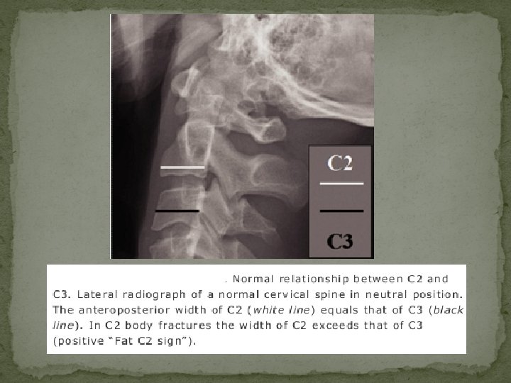
Plain film findings v Lateral view: The fracture usually is diagnosed readily on the lateral radiograph in >90% of cases unless non-displaced. ▪ Prevertebral soft tissue swelling or hematoma, often absent ▪ Fractures are often anterior to the inferior facets. They are oblique, extending from superior/posterior to inferior/anterior ▪ Positive axis ring sign, which will show posterior ring disruption from atypical fractures extending into the posterior C 2 vertebral body cortex ▪ “Fat C 2 sign” ▪ Posterior displacement of the C 2 spino-laminar line of >2 mm, ▪ An avulsion fracture of the anterior margin of the axis or anterior superior margin at C 3 is often present and identifies the site of rupture of the anterior longitudinal ligament v AP view: Usually not visible on AP cervical spine radiograph.
CT findings CT is valuable to exclude or verify fracture line extension into the vertebral foramina or vertebral body, or to detect subtle concurrent adjacent injuries. v Axial images: ▪ Identify the sites of C 2 ring fractures and extension into the vertebral foramina or vertebral body. ▪ Establish separation between fracture fragments of the pars interarticularis of C 2 v Sagittal reconstruction: ▪ Assess the fractures lines and posterior displacement of the C 2 spinolaminar line ▪ Assess C 2 -3 disc space ▪ Establish separation and angulation between fracture fragments of the pars interarticularis of C 2
Fat C 2 sign C 2 ring sign
Classification of the hangman fracture �Type I fracture - an isolated “hairline” fracture, with < 3 mm fragment displacement, < 15 -degree angle at the fracture site, and normal C 2 -3 disc space �Type II injuries - > 3 mm of fragment displacement or more than a 15 -degree angle at the fracture site and an abnormal C 2 -3 disc space �Type III consists - changes that characterize type II injury + C 2 -3 articular facet dislocation
Type I hangman fracture
Type II hangman fracture
Type III hangman fracture
Odontoid Fractures Classification of dens fractures (Anderson and D'Alonso ) based upon the location of the fracture site with respect to the dens � Type I - an oblique fracture of the superior lateral aspect of the dens, avulsed by the alar (“check”) ligament; this is an extremely uncommon injury, occurring in < 4% of odontoid fractures � Type II - fracture at the base of the dens (most common - comprising 60% of dens fractures ) � Type III - an oblique fracture of the superior portion of the axis body caudal to its junction with the base of the dens
Odontoid fractures
Plain film findings The radiologic diagnosis of odontoid fractures usually is established using the lateral cervical and open-mouth odontoid view radiographs. ü Open-mouth odontoid view: � Type II odontoid fractures - transverse or oblique transverse fracture through the lower portion of the dens. The transverse fracture at the base of the dens must be differentiated from a developmental abnormality termed as os odontoideum. ü Os odontoideum is rounded, has a cortical margin around its entire surface, and is usually more widely separated from the base of the odontoid than a fracture, and with smooth margin. Nonunion odontoid fractures may be impossible to distinguish from an os odontoideum.
Lateral view: (Difficult diagnosis on the lateral view) � Minimal displacement often precludes demonstration of the fracture line. � Positive axis ring sign will show posterior or anterior ring disruption in type III fractures � Type III fractures are almost always better visualized on the lateral projection and may not be evident on the anteroposterior view � Anterior or posterior displacement of the C 2 spinolaminar line of >2 mm � “Fat C 2 sign” in type III fractures
Unstable � If the odontoid fragment is displaced by >5 mm, a 75% nonunion rate results � Odontoid fracture with anterior or posterior displacement of the C 2 spinolaminar line of >2 mm � Multilevel fractures (C 1 and C 2) are considered unstable � Odontoid fractures with atlanto-axial dissociation.
Type I odontoid fracture
Type II odontoid fracture
Type III odontoid fracture
Atlanto-axial Dissociation � Defintion - Acute traumatic atlanto-axial dissociation (AAD) is a rare injury in which there is partial (subluxation) or complete (dislocation) derangement of the lateral atlantoaxial articulations � Certain congenital conditions can be associated with AAD, including Down syndrome, osteogenesis imperfecta, neurofibromatosis, Morquio syndrome, spondyloepiphyseal dysplasia congenita, and chondrodysplasia punctata. � Neurologic symptoms occur when the spinal cord is involved
Types � Type I AAD: AAD with rotatory fixation without anterior displacement of the atlas. This is the most common type of rotatory fixation and occurs within the normal range of rotation of the atlanto-axial joint � Type II AAD: Rotatory fixation with < 5 mm of anterior displacement of the atlas. This is the second most common type and is associated with deficiency of the transverse ligament. � Type III AAD: Rotatory fixation with > 5 mm of anterior displacement of the atlas. This degree of displacement implies deficiency of the TAL. � Type IV AAD: Rotatory fixation with posterior displacement of the atlas. This is the most uncommon type and occurs with deficiency of the dens, such as in type II odontoid process fractures or unstable os odontoideum (congenital or posttraumatic).
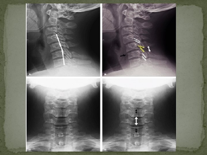
Atlantoaxial rotatory subluxation associated with left lateral mass of C 1 fracture A: shows rotation of C 1 to the right. B: fracture of the left lateral mass of C 1 C: asymmetry of the lateral atlanto-dental spaces (black arrows) and a difference in the atlantoaxial joint spaces (white arrows) secondary to rotational malalignment. Increased transverse diameter of the left lateral mass of C 1 (black dot) and truncated appearance on the right (white dot) indicate rotation of C 1 to the right.
� Anterior translation of C 1 evidenced by the abnormally wide (>> 5 mm) anterior atlantodental interval (AADI) � Anterior position of its spinolaminar line (yellow line in B) with respect to that of C 2 -3 spinolaminar lines
Lower Cervical Spine Injuries (C 3 -7) � Flexion Injuries – Cla y-shoveler fracture, Anterior Subluxation , Simple Wedge Compression Fracture, Flexion Teardrop Fracture � Flexion rotation injuries -Unilateral Facet Dislocation � Extension injuries – Dislocation, Extension teardrop fracture, Laminar fractures � Extension rotation – pillar fracture � Vertical Compression - Burst Fracture
Clay-shoveler Fracture � Avulsion injury of the spinous process of C 6, C 7, or T 1 (in order of frequency). � The fracture results from abrupt flexion of the head and neck against the tensed ligaments of the posterior aspect of the neck � The name is derived from the cervical spine injury sustained by Australian clay miners � Posterior longitudinal ligament remains intact � The typical clay-shoveler fracture is both mechanically and neurologically stable.
Clay-shoveler Fracture
Anterior Subluxation � Occurs when posterior ligamentous complexes (nuchal ligament, capsular ligaments, supraspinous and infraspinous ligaments, ligamenta flava, posterior longitudinal ligament) rupture and a minor tear of the annulus posteriorly � The anterior longitudinal ligament remains intact. � No associated bony injury is seen. � Mechanism - Anterior subluxation is caused by a combination of flexion and distraction. � Anterior subluxation is considered clinically significant because of the morbidity associated with the 20% to 50% incidence of failure of ligamentous healing or “delayed instability. ”
Plain film findings: Lateral view: The findings of AS seen in neutral position become exaggerated upon flexion and are reduced in extension � Widening of the interspinous distance at one level (“fanning”), relative to adjacent levels � Incongruity and lack of parallelism of the contiguous facets � Disc space is widened posteriorly and narrowed anteriorly � Small anterior superior compression fractures of the subjacent vertebral body � Increased thickness of the prevertebral soft tissues as a result of hematoma formation
UNSTABLE: �▪Anterior translation of the vertebral body >3. 5 mm relative to the subjacent vertebra �Vertebral body angulation >20 degrees relative to the adjacent vertebra.
Simple Wedge Compression Fracture � Mechanism - result of compression of the anterior aspect of the vertebral body � Loss of vertebral body height, predominantly anteriorly � The simple wedge fracture is characterized radiographically by an impaction fracture of the superior endplate of the involved vertebral body while the inferior endplate remains intact � The simple wedge fracture is considered mechanically stable.
Bilateral Facet Dislocation � Extreme form of anterior subluxation � Ligamentous disruption and significant displacement of the spine at the level of injury anterior � It usually occurs in the lower cervical spine � The spinal canal is severely compromised by this displacement, and spinal cord injuries are frequent � MRI is the modality indicated for subsequent imaging of patients with BFD as it best assesses the nature and extent of spinal cord injury as well as any associated disc and ligamentous injury
Plain film findings: Lateral view: � Displacement of >50% of the antero-posterior diameter of the vertebral body � Dislocation of articular facets � Narrowing of the disc space at the injured level � Increased thickness of the pre-vertebral soft tissues secondary to hematoma formation. AP view: � Increased inter-spinous distance at the level of dislocation.
Anterior subluxation < 25 % Unilateral facet dislocation 25 – 50 % Bilateral facet dislocation >> 50 %
CT findings: CT is valuable for detection of radiographically occult fractures of the posterior arch or articular facets. Axial images: �Fractures undetectable at plain radiography may be revealed. �“Reverse hamburger bun” sign is useful in establishing a diagnosis of facet dislocation �“Naked facet sign”: refers to the CT appearance of uncovered articulating processes on axial CT images.
Bilateral facet dislocation – Double vertebral body sign
Naked facet sign
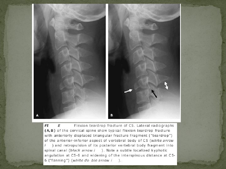
Flexion Teardrop Fracture � represents the most severe injury of the cervical spine � highly unstable injury � typically involving the lower cervical spine (especially C 5) � there is also complete disruption of all soft tissues at the level of injury, including the posterior longitudinal ligament, intervertebral disc, and anterior longitudinal ligament � typical large triangular fracture fragment of the anteroinferior margin of the upper vertebral body (teardrop fragment) Ø The flexion teardrop fracture can be distinguished from the similarly named hyperextension teardrop fracture by the larger size of the triangular fragment and by distraction of the posterior elements (indicating the flexion mechanism).
Hyperextension injuries �most often encountered in elderly patients with severe spondylosis or with spinal ankylosis from other etiologies �Mechanism - In hyperextension fracture dislocation the posterior spinal elements experience impaction forces, producing loading fractures of the posterior vertebral body, laminae, spinous process, or pedicles �Characteristically, the spine above the level of injury is posteriorly displaced (retrolisthesis), the intervertebral disc space is widened anteriorly and narrowed posteriorly and the facet joints are disrupted
Hyperextension teardrop fracture
Burst fracture
Imaging of Thoracolumbar Spinal Injury
�The spinal canal size in the thoracic region averages 16 (AP) by 16 mm (trans), whereas in the lumbar spine the canal averages 17 (AP) by 16 mm (trans) �Thoracolumbar junction is a region of transition and accounts for a greater propensity for injuries in this region - 2/3 rd of all thoracolumbar fractures occur at T 12, L 1, or L 2 �Thoracic spinal trauma has more chances of neurological damage because Ø lumbar spine is more capacious Ø cord terminating as the conus medullaris at the L 1 level Ø cauda equina, unlike the spinal cord, are relatively resistant to blunt trauma
Flexion/Compression Injury � typical anterior wedge compression fracture � upper and mid-thoracic spine due to the kyphotic curvature � Neurologic instability is rare in this fracture � Usually involves only the superior endplate Ø It is distinguished from Scheuermann disease and physiologic anterior vertebral wedging; the latter two usually involve both superior and inferior endplate � Bimodal distribution, occurring in the young (in the context of high-speed trauma) and in the elderly (osteoporosis). � Axial/burst fractures, in contradistinction, have symmetrical reduction in height of the anterior and posterior vertebral margins
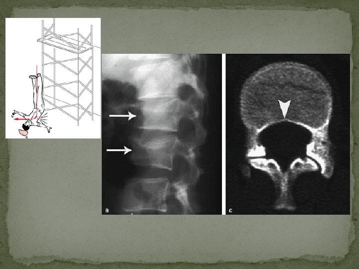
Axial Load Injury (vertical compression) �burst fractures of the thoracolumbar junction and lumbar spine �classically occurs after landing on both feet or buttocks following a fall from a height (lover's fractures when associated with bilateral calcaneal fractures) �Rarely, due to seizure or electrocution
Mechanism – �Axial compression of the vertebral body from above by the nucleus pulposus, which explodes into the superior vertebral endplate to result in centripetal displacement of the body and its fracture fragments �The retropulsion of the posterior aspect of the vertebral body into the spinal canal is pathognomonic of a burst fracture �As the PLL is often intact, spinal traction can reduce this displaced fragment by tightening the PLL
�Posterior bowing of the vertebral body margin is diagnostic of an axial compression (burst) fracture.
Laminar spit fracture
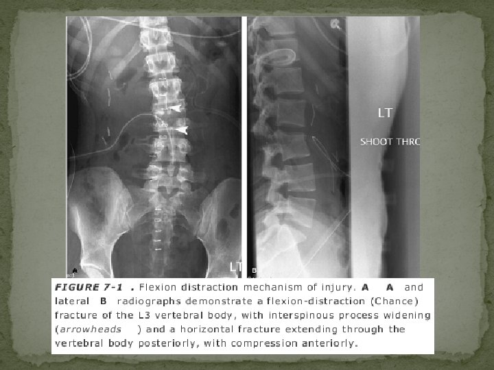
Flexion/Distraction Injury �most common at the thoracolumbar junction �separation in a cranial-caudal direction. �Resultant fracture is called Chance’s frcature. �Mechanism - result of hyperflexion of the upper thoracic spine while the lower spine remains relatively fixed �classically caused by a deceleration-type motor vehicle accident
“Classic Chance fracture” : �The classic Chance fracture accounts for approximately 50% of Chance-type injuries �A “classic” Chance fracture - consists of a pure osseous injury in which there is a horizontal split through the spinous process, lamina, pedicles, resulting in a small anteroinferior corner fracture of the lower vertebral body �acutely unstable �purely an osseous disruption; it also has excellent healing potential with good prognosis for long-term stability �Incidence of neurologic deficit is low, estimated at 10%
�AP radiographs - “double” spinous process, interspinous distance widening, and horizontal fractures through the pedicles �lateral radiograph is often unreliable due to overlap Chance variants – �are either a combined osseous/soft tissue injury or pure �The fracture may extend through the posterior elements as for the classic Chance fracture, but continues anteriorly through the disc or it may involve the posterior ligaments and vertebral body. soft tissue disruption.
Shear injury: Severe unstable three column injuty. Neurologic impairment is frequent. High association with thoracic and abdominal injury
Extension Injury �The resultant radiographic pattern is characterized by posterior element impaction, with fractures (often comminuted) of the spinous process, lamina, or facets, in association with anterior disc widening or avulsion fracture of the anterior endplate Mechanism
Transverse Process Fractures � The injury should serve as a sentinel sign, alerting one to the possibility of other injury Ø For example, an isolated L 5 transverse process fracture is commonly seen in association with a vertically oriented sacral fracture (Malgaigne fracture/dislocation) on the same side
Transverse process fracture associated with a sacral fracture
Sacral traumatic fractures Isolated sacral fractures are uncommon Transverse fractures • most common type • Common at S 3 -S 4 level • High horizontal fractures occur from high falls (suicidal jumper’s fracture) Vertical fractures – • Usually indirect trauma to pelvis • Usually runs entire scrap length
Coccygeal fractures �Most are transversely oriented �AP radiograph – not useful �Lateral radiography – anteriorly tilted / displaced coccyx
Magnetic Resonance Imaging of Acute Spinal Trauma
Ligamentous and Joint Disruption � MRI is the only imaging modality available that directly visualizes changes to the ligaments as a result of trauma � ligaments appear relatively hypointense to other structures on all MRI pulse sequences � Edema or tear - increase in signal intensity on T 2 -weighted or GE images because of an increase in free water content from extracellular fluid or adjacent hemorrhage � Because of the similarity in imaging characteristics, distinction between a ligament fragment and cortical bone fragment may prove difficult on MRI
• Extensive degenerative changes noted but no gross evidence of malalignment • The ALL, LF and PLL are disrupted. • There is widening of the interspinous distance • Edema in the posterior paraspinal soft tissues • damaged intervertebral disc
Disc changes in trauma can be classified as either disc injury or disc herniation �Disc injury - is implied whenever there is � asymmetric narrowing or widening of an isolated disc space on sagittal images and � focal hyperintensity of the disc material on T 2 -weighted images � potentially hemorrhagic MR signal changes of a damaged disc may therefore be, in part, due to damage to the adjacent endplates �Disc herniation – � similar MRI appearance to nontraumatic disc herniation
• acute angulation of C 3 on C 4 with spinal cord compression • large herniated disc fragment (arrow) compressing the spinal cord • free edge of the ruptured PLL adjacent to the disc fragment
Epidural Hematoma � The imaging characteristics of epidural hematomas are variable as they depend on the oxidative state of the hemorrhage and the effects of clot retraction � In the acute phase, Ø isointense with spinal cord parenchyma on T 1 -weighted images Ø isointense with CSF on intermediate- and T 2 -weighted sequences Ø The epidural collection may be difficult to distinguish from the adjacent CSF in the subarachnoid space. Ø This distinction can often be made by the hypointense dura, which separates the two compartments
• A large dorsal epidural hematoma is displacing the posterior margin of the dura • The roots of the cauda equina are compressed against the vertebral body by the hematoma
Spinal Cord Injury �The depiction of parenchymal SCI on MRI not only correlates well with the degree of neurologic deficit, but it also bears significant implications in regard to prognosis and potential for neurologic recovery �Imaging characteristics are due to accumulation of edema and hemorrhage within the substance of the cord parenchyma
absence of an obvious fracture or subluxation T 2 -weighted MRI with fat suppression shows the compression of the spinal cord edema within the spinal cord at the C 3 -4 level (arrow) and prevertebral edema Spinal cord injury without radiographic abnormality (SCIWORA)
Spinal Cord Hemorrhage �The most common location is within the central gray matter of the spinal cord �Centered at the point of mechanical impact
� small focus of hyperacute hemorrhage at C 1 -2 (arrow) and very subtle high-intensity edema Two days later, more obvious edema extending down to C 4 and clear hemorrhage in deoxyhemoglobin state is seen, particularly on axial GRE (C), where hemorrhage is noted within central portion of spinal cord
Spinal Cord Edema �focus of abnormal high signal intensity on T 2 -weighted images �Edema involves a variable length of spinal cord above and below the level of injury, with discrete boundaries adjacent to uninvolved parenchyma
Spinal cord transection
Conclusion � Imaging plays a pivotal role in assessing the mechanical and neurologic stability of the traumatized thoraco-lumbar spine. � Radiography is still preferred in low risk “reliable” (awake, alert, normal mental status, and no significant distracting pain) subjects. � CT is the preferred imaging modality in subjects at high risk of injury, however, because of higher sensitivity and specificity. � CT, with the use of high-resolution multiplanar and 3 D reformations, has resulted in improved fracture pattern classification with better differentiation between stable or unstable injuries. � MRI is still the only imaging method that demonstrates the soft tissue components of injury and provides an objective assessment of the damaged spinal cord's internal architecture