EET 424 POWER ELECTRONIC FOR ENERGY SYSTEM LECTURE


 Some appliances can be")
 A power quality is defined as “ any power")


 Power Frequency Disturbances – are low freq. phenomena that result in voltage")
 Electromagnetic Interference (EMI) – the interaction between electric and magnetic fields and sensitive")


")


 • Decrease to between 0. 1 to 0. 9 p. u.")


 DC offset • Presence of a dc voltage or current in an AC")

: • Ratio of rms voltage or current")
: • Ratio between active power (W)")
: • Ratio of total active power to total apparent")

 IEC 61000 -3 -2 i) Class A : Balanced three-phase equipment and all")


 Inter-harmonics • Caused by waveforms that have frequency components that are")
 Electrical Noise • Caused by a low voltage, high frequency (but lower than")
 Voltage fluctuation • Rapid changes in voltage within the allowable limits of the")
 Utility")

 Consumer or end-user side : Nonlinear loads, harmonic resonance due capacitor switching, poor")

 • Electric arc furnaces, arc welders and electric")


 Curve")


 Design")
 Earthing / Grounding practices • • Power quality problem can caused")
 Reducing the number of faults • For examples tree-trimming, animal guards, shielding wires")
 Sectionalizing / Ring Supply with Line Recloser • Used to transfer a load")
 Surge")
 Surge suppressors / arresters – protect equipment against transient overvoltages, voltage surges and")
 Noise Filters – Prevent high frequencies signal from entering and leaving an equipment,")
 Isolation Transformers Isolate sensitive loads from transients and high frequency noise of the")
 Low-Voltage Line Reactors Use to reduce minor voltage variations or fluctuations due to")
 Various line-voltage regulators a) Transformer with electronic tap changers n n n Electronic")
 Constant Voltage Transformer (CVT) or Ferroresonant Transformer • Ferroresonant txt has 1: 1")
 Motor-generator sets are used to provide voltage regulation, by control of generator field")
 Dual feeders with static transfer a) Static VAR Compensator (SVC) n n n")

 Static synchronous compensator (STATCOM) • STATCOM is a shunt connected, solid state device")


 connected on")
 Dynamic voltage restorer (DVR) • Primary function: to minimize the voltage sags")


 Synchronous condensers • Synchronous condensers are also known as “ rotary synchronous condensers”.")
 UNINTERRUPTIBLE POWER SUPPLY (UPS) • • • a. STANDBY UPS b. ONLINE UPS")
 Standby UPS Consists of rectifier, battery, inverter and static switches. Static switch is")
 Online UPS • Load is always fed from the UPS; in this way")
 Hybrid UPS • Configuration similar to standby UPS system. • The only exception")
 HARMONIC FILTERS • • a. ACTIVE FILTER b. PASSIVE FILTER")

 Passive filter • • • A simple filter consist of discrete (static) capacitors")


- Slides: 87
EET 424: POWER ELECTRONIC FOR ENERGY SYSTEM LECTURE 1: POWER QUALITY BY: DR SYAHRUL ASHIKIN AZMI
Overview of Power Quality in Electrical Power Systems • To ensure mains supply voltage is 240 Vac (1 -ph) or 415 Vac (3 -ph). • To ensure supply frequency is 50 Hz. • To ensure no harmonics in the supply system. • To ensure the mains supply voltage is always sinusoidal. • To ensure enough power can be delivered to a load.
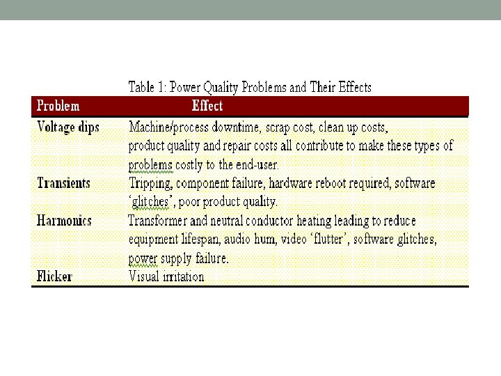
Problems that will occur if having power quality issues: i) Some appliances can be damaged (CPU, monitor, TV, SMPS). ii) Malfunction, mis-operation and less reliability of equipment. iii) Shorten life expectancy of equipment. iv) Excessive heating of cables, motors and transformers. v) Protection relays false tripping. vi) Instrumentation measurements wrongly acquired. vii) Flickering of lighting – detrimental to health. viii) Economic impact – unattractive infrastructure to investors.
Terminologies of Power Quality a) A power quality is defined as “ any power problem manifested in voltage, current or frequency deviations that results in failure of missed operation of utility or end user equipment. ” - i) Roger Dugan, Mark Mc Granaghan, and Wayne Beaty in Electrical Power Systems Quality, Mc. Graw-Hill, 1996. ii) Barry W. Kennedy in Power Quality Primer, Mc. Graw- Hill, 2000. b) “ Power quality is a set of electrical boundaries that allows a piece of equipment to function in its intended manner without significant loss of performance or life expentancy. ” - C. Sankaran in Power Quality, CRC Press, 2002. c) “ The concept of powering and grounding sensitive electronic equipment in a manner suitable for the equipment. ” - IEEE Standard 1100. In this course, we accept only the terminology (a) as our reference definition of power quality, because (a) covers power supply criteria from both sides, utility and end-user point of views.
Growing Concerns of Power Quality • Load equipment is more sensitive to PQ variations than equipment applied in the past. Present loads contain u. P controls and power electronic devices. • The increasing of harmonic levels of power systems as growth in adjustable speed drives (ASD), switching mode power supplies (SMPS) – people concerned about the future impact on system capabilities. • The end users having better knowledge and awareness of PQ such as interruptions, sags, switching transients – to challenge the utilities in providing better PQ. • Many loads are now interconnected in a network such as servers, telecommunications and remote sensing stations. Failure of any component will result in collapsing of the system.
Typical Electrical Power Distribution System Generator power quality : 50 Hz freq.
Power Quality Scope of Concerns
Explanations: 1) Power Frequency Disturbances – are low freq. phenomena that result in voltage sags or swells. Due to faults or switching operations in power systems. 2) Power System Transients – are fast , short-duration events that produce distortions such as notching, ringing and impulse. • Power System Harmonics – are low freq. phenomena characterized by waveform distortion, which introduce harmonic freq. components. • Grounding and Bonding – first as electrical safety factor, second as to provide a low impedance path for the flow of fault current in case of ground fault, so as to isolate the faulted circuit from power source, third, as to create a ground reference plane known as signal reference ground (SRG).
5) Electromagnetic Interference (EMI) – the interaction between electric and magnetic fields and sensitive electronic circuits and devices, predominantly a high-freq. phenomenon. Radio Frequency Interference (RFI) – the interaction between conducted or radiated radio frequency fields and sensitive data and communication equipment. 6) Electrostatic Discharge (ESD) – harmful to electronic circuits, causing malfunction and damage. 7) Power Factor – low power factor, related to an economic issue. Need over-sizing of a power system, higher generation capacity, larger distribution transformers and cables.
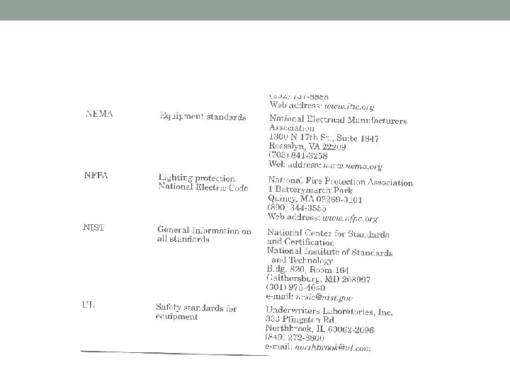
POWER QUALITY STANDARDS_ The purpose of PQ standards is to protect utility and end user equipment from failing or mis-operating when the voltage, current or frequency deviates from normal. There are various standards organizations through-out the world to cover PQ requirements determined by the related committees or regulatory authorities. The standards either set to meet the requirements of power supply system to consumers or equipment that produced by manufacturers.
List of organizations publishing PQ standards_
For our studies, we concentrate only on these 2 organization standards. 1. IEEE – Institute of Electrical and Electronic Engineers. (USA) 2. IEC – International Electrotechnical Commission. (Europe)
List of PQ and related standards of IEEE
List of PQ and related standards of IEC
IEC Standard for PQ classes
(for the PQ community)
Important definition of Sine-wave values
Refer to the categories and characteristic of power system electromagnetic phenomena (for the PQ community) A. Transients: Undesirable momentary deviation of the supply voltage or load current. Also known as surges or spikes. 2 categories of transients: impulsive and oscillatory • Impulsive transients: a sudden, non-power frequency change in the steady-state condition of voltage, current or both, that is unidirectional in polarity (either +ve or –ve). • Oscillatory transients: same definition as impulsive but the only different is bidirectional in polarity (includes both +ve or –ve values). • High-frequency oscillatory transient- greater than 500 k. Hz • Medium-frequency oscillatory transient – between 5 k. Hz to 500 k. Hz • Low-frequency oscillatory transient – less than 5 k. Hz.
Impulsive transient Oscillatory transient
B. Short duration voltage variation: Interruption, sag and swell. Each type can be designated as instantaneous(0. 01 -0. 5 sec), momentary (0. 5 -3 sec) or temporary (3 -60 sec) Interruption a reduction in the supply voltage, or load current, to a level less than 0. 1 p. u for a time less than 1 minute. It can caused by system faults, system equipment failures or control and protection malfunctions. interruption
Voltage sag (dip) • Decrease to between 0. 1 to 0. 9 p. u. in rms voltage at the power frequency for durations from 0. 5 cycles(8 ms) to 1 minute. Also called voltage dips. Caused by faults, increased load demand transitional events such as large motor starting. Voltage sag
Voltage sag
Voltage sag
Voltage swell • An increase in rms voltage in the range of 1. 1 to 1. 8 p. u. for duration from 0. 5 cycles (8 ms) to 1 minute. Also called momentary overvoltage. Caused by system faults, load switching and capacitor switching. Instantaneous voltage swell caused by a SLG fault.
Voltage swell
C. Long duration voltage variations: Voltage deviation longer than 1 min. 3 types: • Overvoltage - An increase in the rms ac voltage greater than 110% at power frequency for duration more than 1 minute • Undervoltage - A decrease in rms ac voltage to less than 90% at power frequency for duration more than 1 minute • Sustained interruption - When voltage is 0 for duration more than 1 minute.
D. Voltage imbalance Deviation of each phase from the average voltage of all three phases. • Most equipment can tolerate voltage imbalance of 2%. • Can cause network problems such as mal-operation of protection relays and voltage regulation equipment, and also overheat of motor and transformer. E. Waveform distortion Steady-state deviation from an ideal sine wave of power frequency. • 5 primary types of waveform distortion: DC offset, harmonics, inter- harmonics, notching and noise.
i) DC offset • Presence of a dc voltage or current in an AC system. • Can result in corrosion of network and customer’s earthing system. ii) Harmonics • Periodic sinusoidal distortions of the supply voltage or load current caused by non-linear loads. • Harmonics are measured in integral multiples of the fundamental supply frequency, 50 Hz (i. e. 150 Hz is third harmonic) • Harmonic current caused by nonlinear loads like adjustable speed drive, SMPS in computer, power electronic devices and medical test equipment. • Effect: overheating of txt, cable and motor; relay trip and incorrect measurement of V and I by meters.
Nonlinear load waveform and harmonic content Creation of nonlinear waveform by adding fundamental and third harmonic frequency waveform
Harmonic distortion. . • Distortion factor (THD): • Ratio of rms voltage or current harmonic content of a periodic wave to the rms of fundamental content of the wave, expressed as a percent. Also known as total harmonic distortion (THD). • % THD = • where : I 1, rms is the fundamental sinusoidal input current and Irms is the input utility rms current (may not be sinusoidal, depends on load)
Harmonic distortion. . • Displacement power factor (DPF): • Ratio between active power (W) to apparent power (VA) of the fundamental wave. DPF is same as PF in linear circuit with sinusoidal V and I. DPF is cosine of displacement angle between V and I waveform. • DPF = cos Φ
• Power factor (PF): • Ratio of total active power to total apparent power of composite wave including all harmonic components.
Harmonic Standards There are few standards that generally practiced by international communities such as in US and European countries, that imposed on the power electronic equipment which is connected to the utility system. a) IEC 61000 -3 -2 - Having four classifications as A, B, C, and D classes depending on the nature of the individual equipment. b) IEEE 519 -1992 - More related to the power or utility provider on the distribution or feeder side as Point of Common Coupling (PCC).
a) IEC 61000 -3 -2 i) Class A : Balanced three-phase equipment and all other equipment that not stated in the following classes. ii) Class B : Portable tools such as hand tools and lawnmowers. iii) Class C : Lighting equipment and including dimming devices. iv) Class D : Equipment having an input current with a “ special waveshape ” and active input power from 75 W to 600 W. Examples are personal computers, monitors, UPS and others that normally having AC to DC rectifiers or Switching Mode Power Supplies (SMPS). IEC 61000 -3 -2 Class D harmonics and current limits. where n is the odd-ordered harmonic number.
Harmonic Current Distortion
Reference book : Power Electronics : Converter, Applications, And Design – Mohan, Undeland, Robin. Chapter 18.
• iii) Inter-harmonics • Caused by waveforms that have frequency components that are not integral multiples of the fundamental frequency, 50 Hz. • The effects of inter-harmonics are light flicker, audible noise in tv sets, radios and audio equipment, and vibration in rotating induction machines. iv) Notching • It is a periodic voltage disturbance caused by normal operation of power electronic devices when current is commutated from one phase to another (two phases of supply are effectively short-circuited for a short time). Notching
v) Electrical Noise • Caused by a low voltage, high frequency (but lower than 200 Hz) signal superimposed on 50 Hz fundamental waveform. • Cause: HV lines, start up of large motor, radio and TV station, SMPS, fluorescent light and power electronic devices. Noise Electrical noise adds “hash” or mess onto the fundamental sine wave
vi) Voltage fluctuation • Rapid changes in voltage within the allowable limits of the nominal voltage, e. g. 0. 9 to 1. 1 p. u. • Cause lamps to blink rapidly, often referred to as “flicker” and is visible to human eyes at flickering frequencies of 6 -8 Hz. • Use static VAR controller (SVCs) to control voltage fluctuation frequency by controlling amount of reactive power supplied to the equipment (i. e. arc furnaces). vii) Power frequency variation • Deviation of power system fundamental frequency from its nominal value (50 Hz or 60 Hz).
SOURCES OF POWER QUALITY PROBLEMS Can be divided into 2 categories : i) Utility side : switching operations, power systems faults, lightning. - On/Off, tripping of breakers can cause voltage sag or swell. - Switching of PF improvement capacitors, can cause an increase in voltage and transients. If tuned to harmonics, can amplify the harmonics and also create harmonic resonance.
- Inter-connected of power system • Increasing levels of interconnection in power system is predicted in the future are likely to have an effect on power quality. The problem can propagate and difficult to isolate. Harmonics and flicker are examples of power quality problems that can be transferred from a utility to another through interconnection. - Lightning Strike and Environmental Related Damage • • Lightning strikes are a cause of transient overvoltages often leading to faults on the electricity supply network. Lightning strikes that hit overhead lines often cause ‘flash-over’ to neighbouring conductors as the insulators break down. The strike will therefore not only consist of a transient overvoltage but also fault-clearing interruptions and dips.
ii) Consumer or end-user side : Nonlinear loads, harmonic resonance due capacitor switching, poor grounding, poor wiring, inadequate lightning protection, electromagnetic interference (EMI), static electricity.
Nonlinear load • Load that has its impedance changing nonlinearly while in operation. Voltage and current do not follow each other linearly. • Examples: Switched Mode Power Supply (SMPS), adjustable speed drive, electronic ballast for fluorescent lamp and power supply for welding machine. • Devices that change smooth sinewave into irregular distorted wave shapes.
• Arcing device (nonlinear load) • Electric arc furnaces, arc welders and electric discharge lamps are all forms of electric arcing device. These devices are highly non-linear loads. • All arcing devices are sources of harmonic distortion. • Load switching • This type of transient might occur as the result of switching in a heavy single-phase load. • Other equipment can be protected from these switching transients by electrically isolating them from the affecting equipment.
• Large motor starting • Dynamic nature of induction machines means that they draw current • • depending on the mode of operation. During starting, this current can be as high as six times the normal rated current. This increased loading on the local network that has the effect of causing a voltage dip. Most modern motors employ a sophisticated power electronic converter ‘drive’, which control the motor’s starting current to a reasonable level. Some lower cost types of motor use series capacitors or resistors to reduce the starting current. These components are then switched out once the motor’s rated speed has been reached. Autotransformers are used to start some older motors. These have a variable secondary winding that allows the motor stator voltage to be controlled and hence the current drawn from the supply.
Sensitive Loads : IT and office equipment • The brain of computer is integrated circuit (IC) chips. Chip is sensitive to changes in power supply. • Computers, microprocessors, consumer electronic and telecommunication appliances used power supplies that consists of a switched mode power supply (SMPS) and are the cause of a significant increase in the level of 3 rd, 5 th and 7 th harmonic voltage distortion. • Any deviation from voltage can cause data to be corrupted or erased.
ITIC (CBEMA) Curve
Summary of Power Quality Issues
POWER QUALITY MEASUREMENT Types of equipment for monitoring power quality: • Digital multimeter • AC Clamp meter (for current measurement) • Oscilloscope • Power Scope • Disturbance analyzer • Power Analyzer • Spectrum and harmonic analyzer
Multimeters Important to consider the calculation method used in a multimeter. Most multimeters are calibrated to give RMS value of a sinewave signal. The reading may not be accurate for other types of signal. 3 most common methods used : a) Peak Method – Meter reads peak value and divides by 1. 414 to get the RMS value. • Averaging Method – Meter determines average value of a rectified signal, and multiply by 1. 11 to get the RMS values. • True RMS – Reading measured through a resistive load, and determines the heating value dissipated by the resistor. More modern meters use sampling signal basis, averaging over the period and then taking square root of the result.
Comparison of meter reading for various waveforms
Power quality measurement equipment capabilities
Power Quality Solutions 4 ways to solve and prevent PQ problems : a) Design equipment and electrical systems to prevent electrical disturbances from causing equipment or systems to malfunction. b) Analyze the symptoms of a PQ problem to determine its cause and solution. c) Identify the medium that is transmitting the electrical disturbance and reduce or eliminate the effect of that medium. d) Treat the symptoms of the PQ problem by the use of suitable power conditioning equipment to mitigate a PQ problem when it occurs.
General Methods 1) Earthing / Grounding practices • • Power quality problem can caused by incorrect earthing practices. Verification of earthing arrangement should be conducted in power quality investigation. Grounding has 4 basic purposes : a) Protect people from electrical shock and equipment from a short circuit fault b) Provide a zero reference point c) Provide noise control d) Provide a path for lightning and switching surge faults
2) Reducing the number of faults • For examples tree-trimming, animal guards, shielding wires and replacing overhead lines by underground lines. • Normally used to solve voltage dip problem. 3) Faster fault clearing • Need to improve protection techniques. • Development of a new generation of circuit breakers and relay at the transmission level. 4) Static breaker • Allow the isolation of faulted circuits in the shortest possible time frame, while other nearby loads will improve the power quality of the network.
5) Sectionalizing / Ring Supply with Line Recloser • Used to transfer a load connection from one supply to another, allowing the choice of two supplies for the load (or sub network). • One of the supply will handle the power disturbances on the system whereas the other one will be automatically switched on to reduce the possibility of supply disruption to the load. 6) Local or embedded generation • A form of local generation, i. e. diesel generator, can be connected to allow for any shortfall (or loss) in the main capacity and also to provide ride-through for power quality disturbances. • Expensive solution since the cost to keep a diesel generator running online.
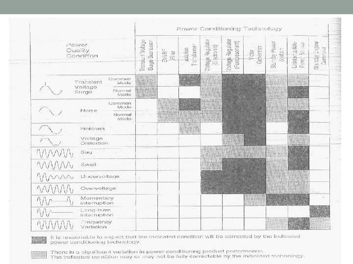
Mitigation / Power Conditioning Equipment Can be divided into 10 categories : 1) Surge suppressors / arresters 2) Noise filters 3) Isolation transformers 4) Low-voltage line reactors 5) Various line-voltage regulators 6) Motor-generator sets 7) Dual feeders with static transfer 8) Synchronous condensers 9) Uninterruptible power supplies (UPS) 10)Harmonic filters
1) Surge suppressors / arresters – protect equipment against transient overvoltages, voltage surges and lightning strokes Instead of just an air gap (for much higher voltage), some surge arresters contain nonlinear resistors (varistors). The varistor resistance decreases as the voltage across it increases. Examples : Metal Oxide Varistor (MOV), zinc oxide, silicon carbide and silicon avalanche diodes (zener).
2) Noise Filters – Prevent high frequencies signal from entering and leaving an equipment, act as low-pass filters.
3) Isolation Transformers Isolate sensitive loads from transients and high frequency noise of the utility. The isolation transformer prevents common-mode noise from reaching the load. In 3 -ph systems when delta-wye isolation transformer is used, the neutral point connected to ground will protect utility from triplen harmonics (3 rd, 9 th, 15 th, etc. ). The triplen harmonics remain in the delta primary circulating around but not entering the utility.
4) Low-Voltage Line Reactors Use to reduce minor voltage variations or fluctuations due to arc furnaces and welding equipment.
5) Various line-voltage regulators a) Transformer with electronic tap changers n n n Electronic tap changers can be mounted on txt for sensitive load to change its turn ratio according to change in input voltage. They are connected in series on the distribution feeder and placed between supply and load. Part of secondary winding is divided into number of sections which are connected or disconnected by fast static switches to allow regulation of secondary voltage in steps. This will allow the output voltage to be brought back to level above 90% of nominal value even during severe sags. Thyristor-based switches only turn on once per cycle, thus accomplish the compensation with a time delay of at least one half cycle.
b) Constant Voltage Transformer (CVT) or Ferroresonant Transformer • Ferroresonant txt has 1: 1 turns ratio and with a core that is highly magnetized close to saturation under normal operation. • This will provide an output voltage which is not affected by input voltage variations hence the output is not significantly affected by voltage sag. • In actual design, a capacitor connected to secondary winding to set the operating point above the knee of saturation curve. • Suitable for low-power, constant loads
6) Motor-generator sets are used to provide voltage regulation, by control of generator field current. The motor connects to the utility and runs the generator through a shaft or belt. It isolates sensitive loads from voltage sags, harmonics, transients, overvoltage and undervoltage disturbances. It provides ride through from input voltage variations, especially voltage sags by storing energy in a flywheel. The major disadvantage is it can take several seconds to bring the voltage back up to the required level, making it is too slow for voltage regulation of certain critical loads.
7) Dual feeders with static transfer a) Static VAR Compensator (SVC) n n n Used to supply reactive power (VAR) to the supply system. The heart of SVC is the thyristor valve, consisting of ‘back-toback’connected, high-power thyristors in series in order to obtain the required operating voltage. The thyristor valve control the current either through reactors to form a thyristor controlled reactor (TCR) or capacitors to form thyristor switched capacitors (TSC) or combination of both TCR and TSC. Thyristor-Controlled Reactor (TCR) Thyristor Switched Capacitor (TSC)
Static VAR Compensator with reactors and capacitors in parallel. • A combination of TSC and TCR is an SVC, as in the majority of cases, the optimum solution. • With this combination, continuous variable reactive power is obtained throughout the complete control range as well as full control of both the inductive and the capacitive parts of the compensator. • This is a very advantageous feature permitting optimum performance during large disturbances in the power system.
b) Static synchronous compensator (STATCOM) • STATCOM is a shunt connected, solid state device that used power electronics to control power flow and improve transient stability on power grids (or power system network). • It also regulates voltage at its terminal by controlling the amount of reactive power injected into or absorbed from the power system. • When system voltage is low, the STATCOM generates reactive power (STATCOM capacitive). • When system voltage is high, it absorbs reactive power (STATCOM inductive).
• As current source active filter
• As voltage source active filter
• Variation of reactive power is performed by Voltage-Sourced Converter (VSC) connected on the secondary side of a coupling transformer. • The VSC uses forced-commutated power electronic devices (GTOs or IGBTs) to synthesize a voltage generated by the VSC from a DC voltage source. • The GTO (gate-turn-off thyristor) is used for higher voltage application while IGBT (integrated gate bipolar transistor) for lower voltage. • STATCOM offer better voltage support and improved transient stability margin by providing more VARs at lower voltages. • This is because the maximum capacitive power generated by a SVC is proportional to the square of the system voltage (constant susceptance) while the maximum capacitive power generated by a STATCOM decreases linearly with voltage (constant current). • Since no large capacitors or reactors are used to generate VARs, STATCOM provides very fast response (no delay associate with thyristor firing) and greater stability to variations in system impedance. • Harmonic elimination by selective firing of the GTOs means that STATCOM has further advantages over the SVC and can be used as an active filter.
C ) Dynamic voltage restorer (DVR) • Primary function: to minimize the voltage sags on lines that cater to sensitive equipment. • Consists of VSC placed in series with the load/distribution feeder by means of an injection transformer. • It can inject voltages of controllable amplitude, phase angle and frequency into the feeder, thus restoring voltage to critical load during sag. • DVR functions as a filter between the transmission line and the facility, thus enabling the facility to continuously receive clean power. It is primarily responsible for restoring the quality of voltage delivered to the end user when the voltage from the source is not appropriate to be used for sensitive loads. • Usage of DVR enables consumers to isolate and protect themselves from transients and disturbances caused by sags and swells on the transmission lines or distribution network.
DVR operating diagram
• This solution is costly but popularly used in large industrial consumers (a few MVA) that have very high power quality demands. • It allows protection of the entire plant from voltage sag through installation of only one device. • The major industries that are likely to benefit the most from DVRs are: • Utilities (transmission and distribution companies) • Process industries (semiconductor plants, paper mills, plastic • • • manufacturers) Automotive manufacturers Chemical plants Electronics (consumer electronic and computer manufacturers) Mining industry Steel plants
• Benefit of DVR: • Reduce losses associated with irregularities in the production process resulting from power disturbances. • A large part of the industrial machinery makes use of sophisticated electronics that are quite sensitive to power disturbances. DVR plays a key role in ensuring the smooth functioning of such equipments. • Power disturbances can lead to irregularities or in a worst-case scenario, stoppage of production processes. Whenever any kind of aberration in power is detected, DVRs reduce the potential shutdown time for equipment within facilities that ultimately saves a lot of time and money. • Can also be used to tackle the problem of harmonics caused by non-linear load machinery in manufacturing facilities. If not corrected in time, the harmonic voltages can spill over to the office power and cut into the productivity. • The insulation wear on transformers, motors and drivers caused by power irregularities can also be reduced by DVR.
8) Synchronous condensers • Synchronous condensers are also known as “ rotary synchronous condensers”. They are synchronous motors that used for power factor correction. A synchronous motor (without load) if its field is overexcited, it will behave like a capacitor, delivers leading current. If normal or under excitation, it behaves like an inductor, delivers lagging current to the load. By adjusting field currents, the motor can be made to operate in lagging, unity or leading PF region. Synchronous condenser for power factor correction
9) UNINTERRUPTIBLE POWER SUPPLY (UPS) • • • a. STANDBY UPS b. ONLINE UPS c. HYBRID UPS
a) Standby UPS Consists of rectifier, battery, inverter and static switches. Static switch is controlled to allow load to be fed from main supply. Switch open and close respectively below some predetermined level. Then, the load will be fed from battery via inverter to ensure continuity of supply to the load. • Inverter output of a standby UPS must always operate in synchronism with the supply frequency to ensure a smooth transition from one supply to the other. • •
b) Online UPS • Load is always fed from the UPS; in this way the load is isolated from the main supply at all times. • Expensive and have high operating losses. • It is very similar to a standby system from view of schematic, but with a manual transfer switch in place of the static transfer switches.
c) Hybrid UPS • Configuration similar to standby UPS system. • The only exception is some form of voltage regulator, such as ferro-resonance transformer (also known as constant voltage transformer, CVT) where it is used in place of the static switches. • The transformer provides regulation to the load and momentary ride-through when the transfer from main supply to standby UPS is made.
10) HARMONIC FILTERS • • a. ACTIVE FILTER b. PASSIVE FILTER
• Harmonic filter • Filter consist of inductors and/or capacitors connected together to block harmonic currents or shunt them to ground. • 2 basic configuration: series and shunt filters. • Series filter consist of capacitor and inductor connected in parallel with each other but in series with load. Provides high-impedance path for harmonic current & block them from reaching power supply but allow fundamental 50/60 Hz current to pass through. • Shunt filter consists of capacitor and inductor connected in series with each other but in parallel with the load. Provides low-impedance path for harmonic current and diverts them harmlessly to ground. Less expensive and more commonly used.
a) Passive filter • • • A simple filter consist of discrete (static) capacitors and/or inductors. Designed to handle specific harmonics. Do not respond to changes in frequency. Referred as trap or choke. Ineffective when harmonic changes due to load changes. b) Active filter • Referred as active power line conditioners (APLCs) and active power factor • • correction (APFC) devices. It condition harmonic currents rather than block or divert them. Use electronic (bridge inverter or rectifier) to monitor & sense harmonic currents and create counter-harmonic current. Then, inject counterharmonic current to cancel out harmonic current generated by load. Also regulate sag and swell by eliminate source voltage harmonic. Most effective in compensating for unknown or changing harmonics.
Summary of mitigation equipment or devices to improve power quality.
Conclusion • Power quality is a well-defined field with growing interest being shown in the solution to the problems, monitoring equipment, regulations and statistical analysis of customers’ expected levels of disturbance. • As future development grow widely, the new materials and devices become available where it may be possible to provide solutions for the cause of the power quality problem rather than treat the symptoms.