Power System Stability Lecture Four Topic Covered Equal

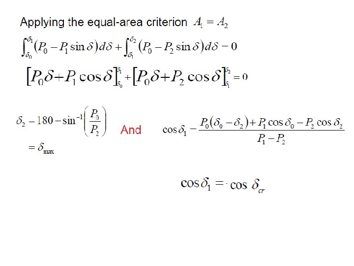
Power System Stability Lecture Four Topic Covered Equal Area Criterion

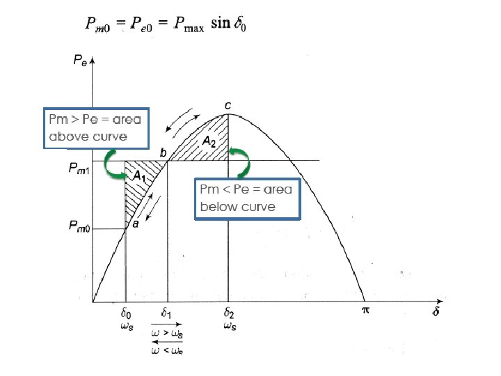
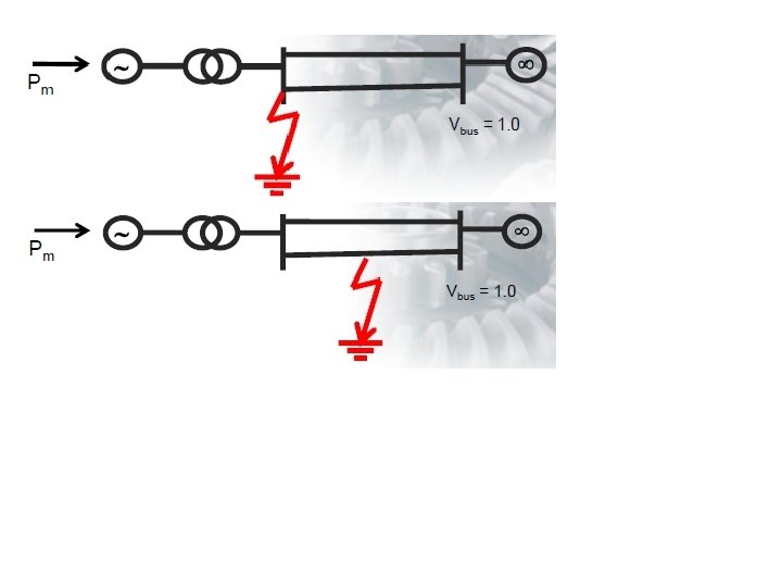
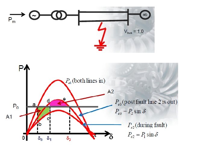
Re-visit Theoretical Event on Rotor Angle, δ • Events relating rotor angle, δ and power delivered by motor • Events include steady state condition and after fault cleared condition • Rotor angle is focused at the intervals of changes in power delivered

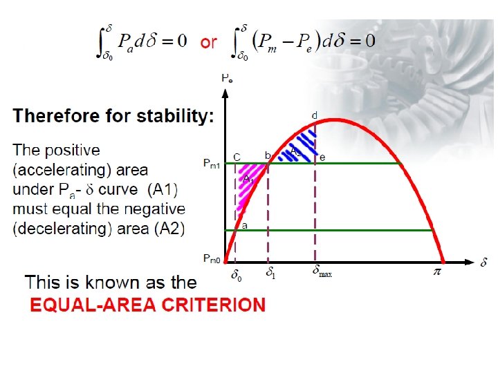
Accelerate area De-accelerate area

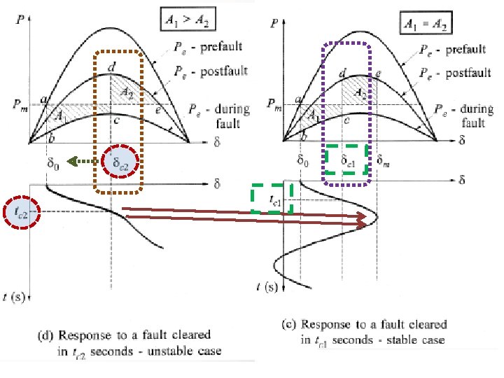
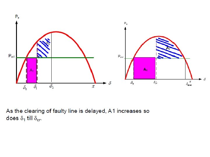
Significance of rotor angle changes to stability of motor Notice the position of δC 2 Impact towards rotor angle Influenced creating time, tcr too

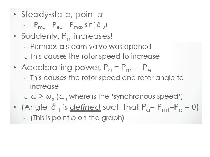
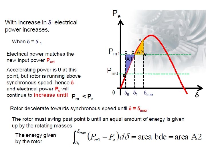
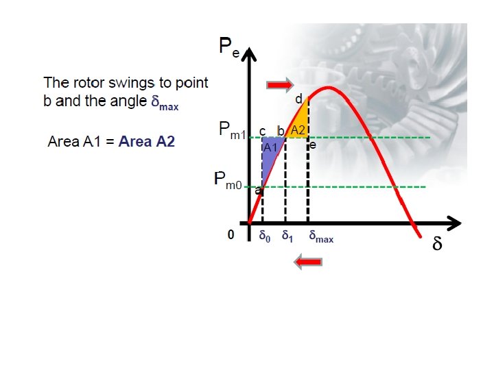
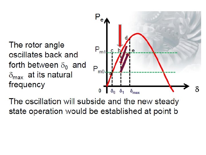
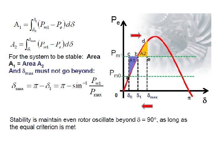
Sudden Change in Mechanical Input

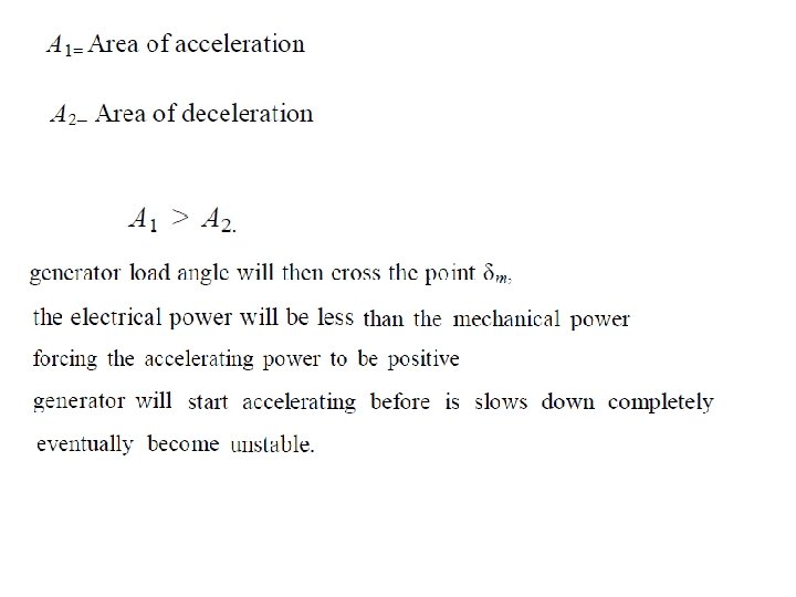
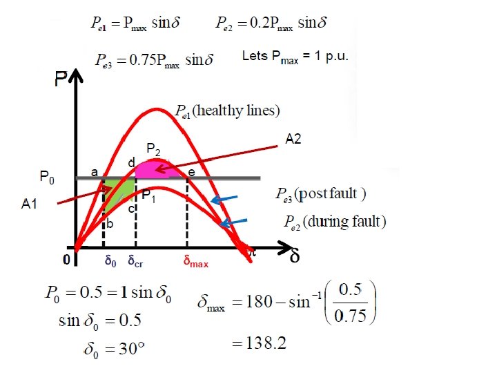
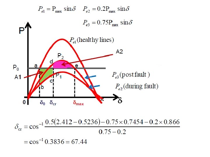
Example 1 A generator operates at 50 Hz delivers 1. 0 p. u power to an infinite busbar through a network. A fault occurs which reduces the maximum power transferable to 0. 4 p. u, whereas before fault power was 1. 8 p. u, and post fault power is 1. 3 p. u. By using equal area criterion, determine the critical clearing angle

Given are: Po = 1. 0 p. u = Initial generator output P 1 = 0. 4 p. u = during fault P 2 = 1. 3 p. u = post fault Pm = 1. 8 p. u = pre fault

Convert electrical degree into radian values

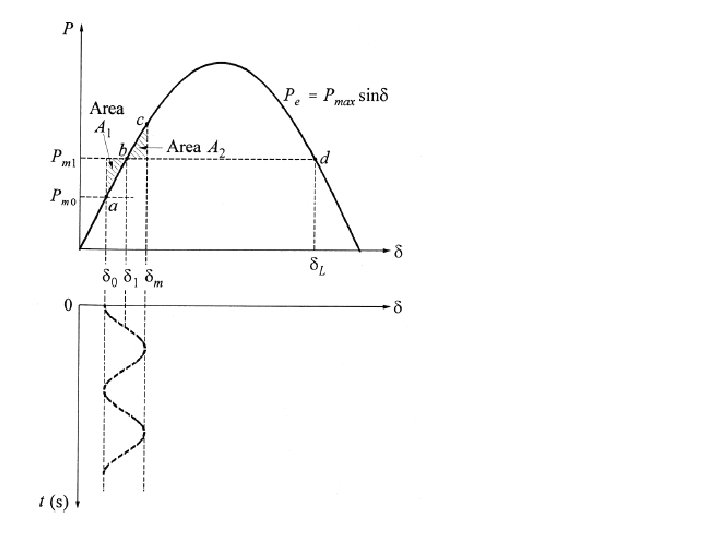
Sudden Increase in Power Input Under this application, there a few scenarios considered
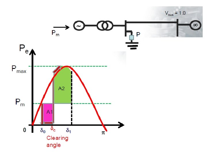

Now that during fault with Pe = 0, swing equation becomes: Integrating both side : Integrating again:

Now the corresponding critical clearing time can be determine:

Example 2

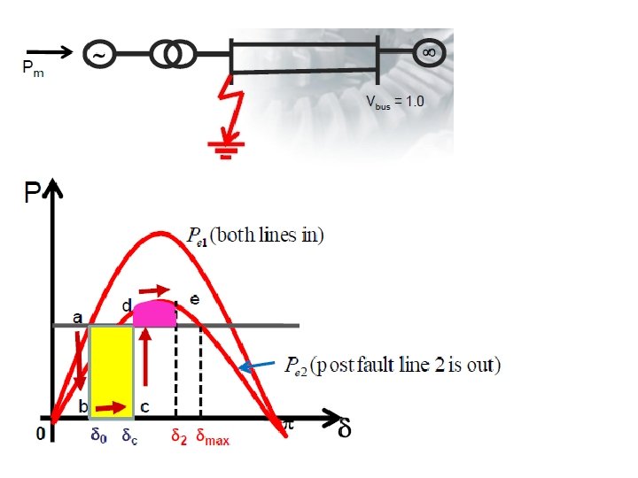
Example 3 A 60 Hz synchronous generator having inertia constant H = 5 MJ/MVA and a direct axis transient reactance Xd’ = 0. 3 p. u. is connected to an infinite bus through a purely reactive circuit as shown below. Reactances are marked on the diagram on a common system base. The generator is delivering real power Pe = 0. 8 p. u. and Q = 0. 074 p. u. to an infinite bus at a voltage of V = 1. 0 p. u. a)Determine the transient internal voltage, E’. b)A three phase fault occurs at the middle of one of transmission lines. The fault is cleared, and the faulted line is isolated. Determine the critical clearing angle. c) repeat (a) and (b) with fault occurs at the sending end.
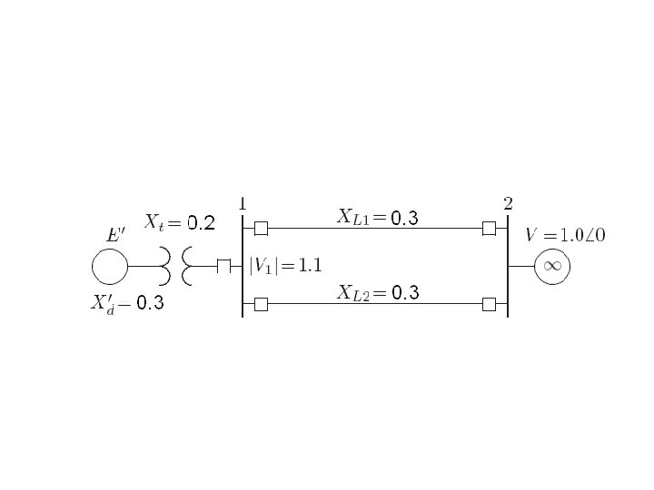

The current flowing into the infinite bus is

The transfer reactance between internal voltage and the infinite bus before fault is:

The transient internal voltage is:

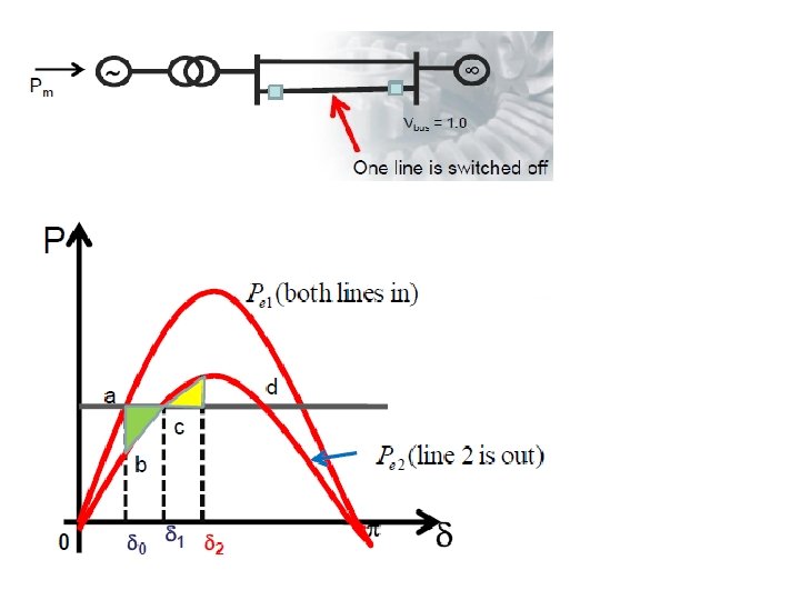
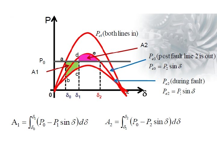
Pre-fault: Since both line are intact when the fault is cleared, the power angle equation at pre-fault:

During fault: The equivalent reactance between generator and the infinite bus

The power-angle curve during fault

Post fault: When fault is cleared the faulted line is isolated. Therefore, the post fault transfer reactance

The power angle curve after fault is
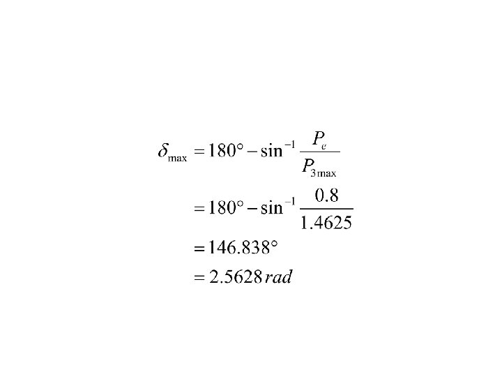

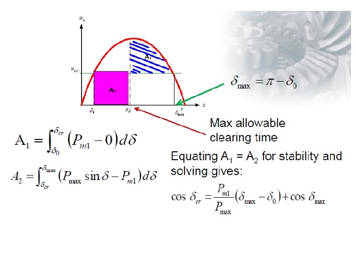
The critical clearing angle

End of Lecture Four
- Slides: 48