EET 1054 ANALOGUE SYSTEMS 2 EET 1054 ANALOGUE

")
")
")
")
")
")
")
")
")
")
")
")
")
")
")
")
")
")
")
")
")
")
")
")
")
")
")
")
")
")
")


- Slides: 39
EET 105/4 – ANALOGUE SYSTEMS 2 EET 105/4 ANALOGUE SYSTEMS II 6. Thyristor and Other Devices Syllabus IDENTIFY and EXPLAIN Shockley diode, SCR and its applications, SCS, Diac, Triac, UJT, Phototransistor, LASCR, Optocoupler.
EET 105/4 – ANALOGUE SYSTEMS 2 6. THYRISTOR AND OTHER DEVICES Unijunction Transistor (UJT) Schematic Symbol Basic Structure
EET 105/4 – ANALOGUE SYSTEMS 2 6. THYRISTOR AND OTHER DEVICES Unijunction Transistor (UJT) RB 1 = dynamic resistance of the silicon bar between the emitter and base 1. RB 1 varies inversely with emitter current IE , and therefore it is shown as a variable resistor. Equivalent Circuit Range of RB 1 : several thousand ohms down to tens of ohms
EET 105/4 – ANALOGUE SYSTEMS 2 6. THYRISTOR AND OTHER DEVICES Unijunction Transistor (UJT) RB 2 = dynamic resistance between the emitter and base 2 Equivalent Circuit
EET 105/4 – ANALOGUE SYSTEMS 2 6. THYRISTOR AND OTHER DEVICES Unijunction Transistor (UJT) The total resistance betweem the base terminals is known as interbase resistance RBBO , i. e. Equivalent Circuit
EET 105/4 – ANALOGUE SYSTEMS 2 6. THYRISTOR AND OTHER DEVICES Unijunction Transistor (UJT) The ratio of RB 1 to the interbase resistance is called the standoff ratio, . Equivalent Circuit
EET 105/4 – ANALOGUE SYSTEMS 2 6. THYRISTOR AND OTHER DEVICES Unijunction Transistor (UJT) If the device is biased as shown in the following figure, the voltage across RB 1 is;
EET 105/4 – ANALOGUE SYSTEMS 2 6. THYRISTOR AND OTHER DEVICES Unijunction Transistor (UJT)
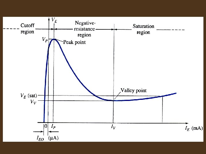
EET 105/4 – ANALOGUE SYSTEMS 2 6. THYRISTOR AND OTHER DEVICES Unijunction Transistor (UJT) As long as VE is less than VBB +VD, there is no emitter current (except a very small leakage current in A known as IEO) because the pn junction is not forward-biased. The level of emitter voltage that causes the pn junction to become forward-biased is called VP (peak-pointvoltage):
EET 105/4 – ANALOGUE SYSTEMS 2 6. THYRISTOR AND OTHER DEVICES Unijunction Transistor (UJT) Once VE reaches VP , IE begins to flow (UJT turns on) – conductivity increases and RB 1 decreases. After turn-on, the UJT operates in a negative resistance region (VE decreases as IE increases) up to a certain level of IE. Beyond this level, VE begin to increase again. The minimum level of VE is known as valley point (VV , IV). Beyond this point, the device enters its saturation region.
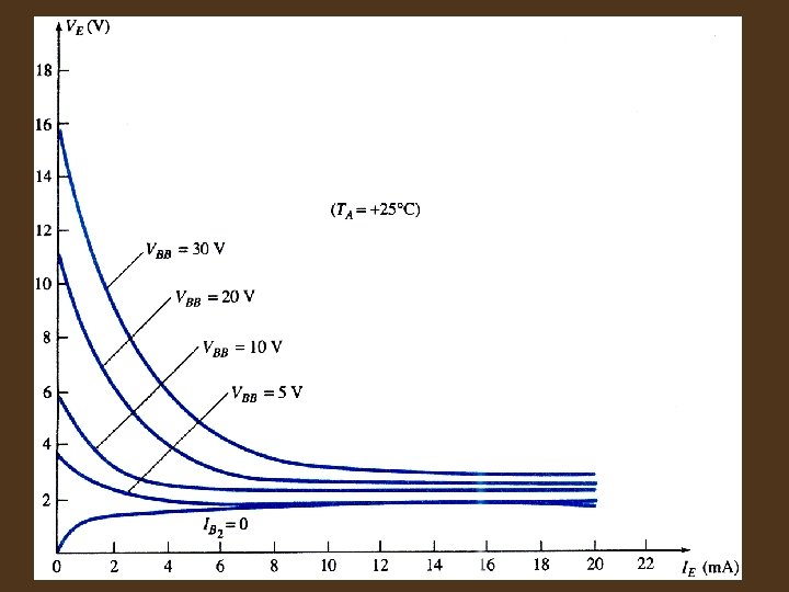
EET 105/4 – ANALOGUE SYSTEMS 2 6. THYRISTOR AND OTHER DEVICES Unijunction Transistor (UJT) For fixed values of and VD, the magnitude of VP will vary as VBB i. e. Fixed
EET 105/4 – ANALOGUE SYSTEMS 2 6. THYRISTOR AND OTHER DEVICES Unijunction Transistor (UJT) Application • Trigger device for SCR’s and triac • Nonsinusoidal (relaxation) oscillators, • Sawtooth generators • Phase control • Timing circuits
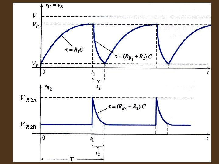
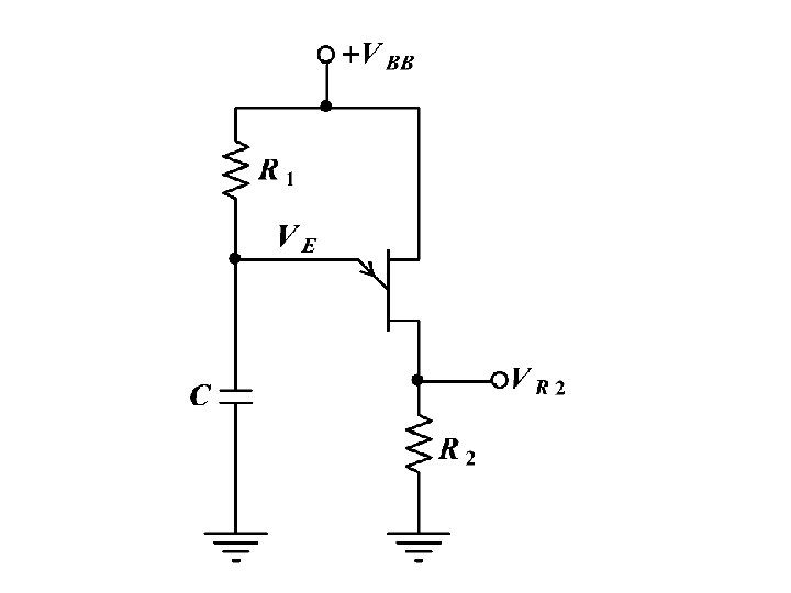
EET 105/4 – ANALOGUE SYSTEMS 2 6. THYRISTOR AND OTHER DEVICES Unijunction Transistor (UJT) Application – relaxation oscillator When the dc voltage +VBB is applied, C charges through R 1 and VE increases exponentially towards +VBB. During this period, the UJT is off.
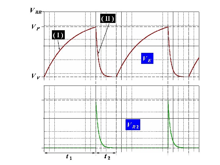
EET 105/4 – ANALOGUE SYSTEMS 2 6. THYRISTOR AND OTHER DEVICES Unijunction Transistor (UJT) Application – relaxation oscillator When VE reaches VP, the UJT turns on and provides a discharge path for the capacitor C. The discharge is rapid since R 2 is small – causing a voltage spike across R 2.
EET 105/4 – ANALOGUE SYSTEMS 2 6. THYRISTOR AND OTHER DEVICES Unijunction Transistor (UJT) Application – relaxation oscillator Towards the end of the discharge process, the current IE decreases to a level that causes the UJT to turn off and hence the charging process restarts. The charge and discharge cycle produces the waveforms shown in the following figure. The output VR 2 can be used to trigger an SCR or a triac in the AC power control circuit.
EET 105/4 – ANALOGUE SYSTEMS 2 6. THYRISTOR AND OTHER DEVICES Unijunction Transistor (UJT) Relaxation oscillator – mathematical analysis Fixing the value of R 1. The value of R 1 is crucial in ensuring that the UJT can turn on and of.
EET 105/4 – ANALOGUE SYSTEMS 2 6. THYRISTOR AND OTHER DEVICES Unijunction Transistor (UJT) At the peak point, in order to swith the UJT to conduction mode, VE and IE must increase to VP and IP respectively.
EET 105/4 – ANALOGUE SYSTEMS 2 6. THYRISTOR AND OTHER DEVICES Unijunction Transistor (UJT) Hence; On the other hand, in order to switch off the UJT at the end of the discharging period, VE and IE must reduce to VV and IV respectively. Hence;
EET 105/4 – ANALOGUE SYSTEMS 2 6. THYRISTOR AND OTHER DEVICES Unijunction Transistor (UJT) Thus, UJT will switch on and off if the value of R 1 lies within the following range;
EET 105/4 – ANALOGUE SYSTEMS 2 6. THYRISTOR AND OTHER DEVICES Unijunction Transistor (UJT) Determination of frequency of oscillation During the charging period t 1 of C; where;
EET 105/4 – ANALOGUE SYSTEMS 2 6. THYRISTOR AND OTHER DEVICES Unijunction Transistor (UJT) The time constant for the discharging period t 2 is given by; RB 1 is the internal resistance between B 1 and E of the UJT. The equation for 2 is quite complicated due to the fact that the value of RB 1 is dependent on IE.
EET 105/4 – ANALOGUE SYSTEMS 2 6. THYRISTOR AND OTHER DEVICES Unijunction Transistor (UJT) However since both RB 1 and R 2 are much smaller than R 1, the voltage VR 2 is given by the approximate equation; The reduced equivalent circuit for the discharge phase is as shown in the following figure;
EET 105/4 – ANALOGUE SYSTEMS 2 6. THYRISTOR AND OTHER DEVICES Unijunction Transistor (UJT)
EET 105/4 – ANALOGUE SYSTEMS 2 6. THYRISTOR AND OTHER DEVICES Unijunction Transistor (UJT) Using the equivalent circuit, the peak value of VR 2 is given by the approximate equation;
EET 105/4 – ANALOGUE SYSTEMS 2 6. THYRISTOR AND OTHER DEVICES Unijunction Transistor (UJT) The period t 1 may be found as follows; When v. C = VP, t = t 1, and;
EET 105/4 – ANALOGUE SYSTEMS 2 6. THYRISTOR AND OTHER DEVICES Unijunction Transistor (UJT) or; and;
EET 105/4 – ANALOGUE SYSTEMS 2 6. THYRISTOR AND OTHER DEVICES Unijunction Transistor (UJT) Hence;
EET 105/4 – ANALOGUE SYSTEMS 2 6. THYRISTOR AND OTHER DEVICES Unijunction Transistor (UJT) For the discharge phase; Setting t 1 as t = 0; and;
EET 105/4 – ANALOGUE SYSTEMS 2 6. THYRISTOR AND OTHER DEVICES Unijunction Transistor (UJT) For the discharge phase; Since
EET 105/4 – ANALOGUE SYSTEMS 2 6. THYRISTOR AND OTHER DEVICES Unijunction Transistor (UJT) And since
EET 105/4 – ANALOGUE SYSTEMS 2 6. THYRISTOR AND OTHER DEVICES Unijunction Transistor (UJT) If we neglect the effect of VD, then; and;
EET 105/4 – ANALOGUE SYSTEMS 2 6. THYRISTOR AND OTHER DEVICES Unijunction Transistor (UJT) or;
EET 105/4 – ANALOGUE SYSTEMS 2 6. THYRISTOR AND OTHER DEVICES Programmable Unijunction Transistor (PUT) In terms of physical structure, PUT is in the thyristor family. However it is closer to UJT in terms of characteristics and applications.
EET 105/4 – ANALOGUE SYSTEMS 2 6. THYRISTOR AND OTHER DEVICES Programmable Unijunction Transistor (PUT) Basic structure Symbol