EET 306 Electrical Machine Synchronous Machine School of


- Slides: 40
EET 306 Electrical Machine Synchronous Machine School of Electrical System Engineering 1 DR. MOHAMAD NUR KHAIRUL HAFIZI BIN ROHANI Senior Lecturer, EET 306 -Electrical Machine Coordinator Blok 3, Cubicle 2 016 -7425020 Ph. D
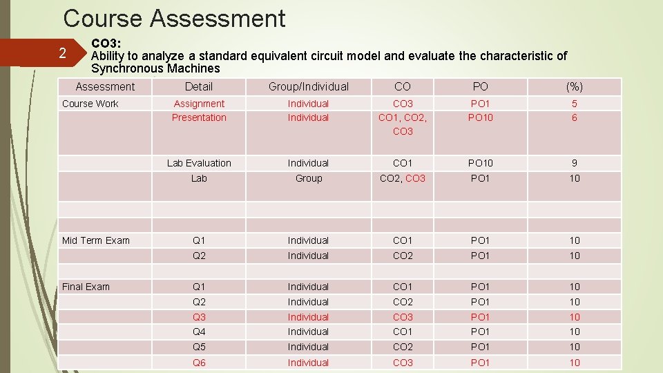
Course Assessment 2 CO 3: Ability to analyze a standard equivalent circuit model and evaluate the characteristic of Synchronous Machines Assessment Course Work Mid Term Exam Final Exam Detail Group/Individual CO PO (%) Assignment Presentation Individual CO 3 CO 1, CO 2, CO 3 PO 10 5 6 Lab Evaluation Individual CO 1 PO 10 9 Lab Group CO 2, CO 3 PO 1 10 Q 1 Individual CO 1 PO 1 10 Q 2 Individual CO 2 PO 1 10 Q 3 Q 4 Individual CO 3 CO 1 PO 1 10 10 Q 5 Individual CO 2 PO 1 10 Q 6 Individual CO 3 PO 1 10
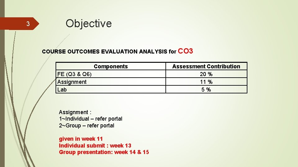
3 Objective COURSE OUTCOMES EVALUATION ANALYSIS for Components FE (Q 3 & Q 6) Assignment Lab Assignment : 1~Individual – refer portal 2~Group – refer portal given in week 11 Individual submit : week 13 Group presentation: week 14 & 15 CO 3 Assessment Contribution 20 % 11 % 5%
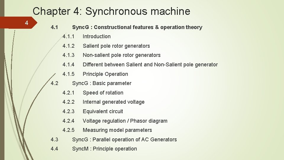
Chapter 4: Synchronous machine 4 4. 1 4. 2 Sync. G : Constructional features & operation theory 4. 1. 1 Introduction 4. 1. 2 Salient pole rotor generators 4. 1. 3 Non-salient pole rotor generators 4. 1. 4 Different between Salient and Non-Salient pole generator 4. 1. 5 Principle Operation Sync. G : Basic parameter 4. 2. 1 Speed of rotation 4. 2. 2 Internal generated voltage 4. 2. 3 Equivalent circuit 4. 2. 4 Voltage regulation / Phasor diagram 4. 2. 5 Measuring model parameters 4. 3 Sync. G : Parallel operation of AC Generators 4. 4 Sync. M : Principle operation
5 4. 1 Sync. G : Constructional features & operation theory RE-CALL ELECTRICAL MACHINE? ELECTRICAL PART? ROTOR? STATOR? FIELD? MOTOR? MECHANICAL PART? ARMATURE? GENERATOR?
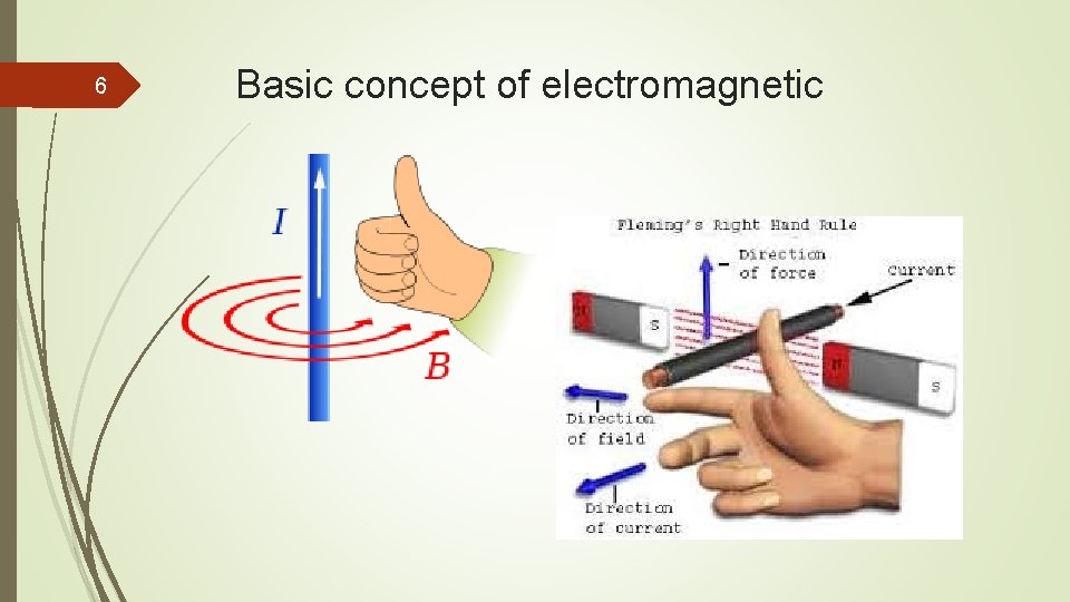
6 Basic concept of electromagnetic
Chapter 4: Synchronous machine 7 4. 1 4. 2 Sync. G : Constructional features & operation theory 4. 1. 1 Introduction 4. 1. 2 Salient pole rotor generators 4. 1. 3 Non-salient pole rotor generators 4. 1. 4 Different between Salient and Non-Salient pole generator 4. 1. 5 Principle Operation Sync. G : Basic parameter 4. 2. 1 Speed of rotation 4. 2. 2 Internal generated voltage 4. 2. 3 Equivalent circuit 4. 2. 4 Voltage regulation / Phasor diagram 4. 2. 5 Measuring model parameters 4. 3 Sync. G : Parallel operation of AC Generators 4. 4 Sync. M : Principle operation
8 4. 1 Sync. G : Constructional features & operation theory 4. 1. 1 INTRODUCTION The two main parts of an electrical machine: Mechanical terms, Rotor is the rotating part. Stator is the stationary part. Electrical terms, Armature is the power-producing component Field is the magnetic field component of an electrical machine. The magnetic field can be provided by either electromagnets or permanent magnets mounted on either the rotor or the stator. Synchronous Generator (SG): aka alternator Rotor magnetic field is produced by PM or applying DC current to rotor winding.
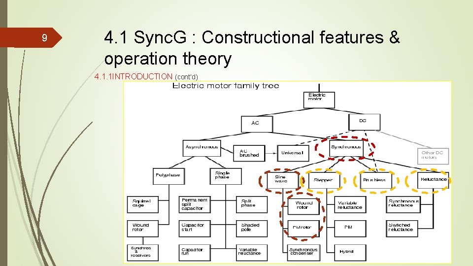
9 4. 1 Sync. G : Constructional features & operation theory 4. 1. 1 INTRODUCTION (cont’d)
Chapter 4: Synchronous machine 10 4. 1 4. 2 Sync. G : Constructional features & operation theory 4. 1. 1 Introduction 4. 1. 2 Salient pole rotor generators 4. 1. 3 Non-salient pole rotor generators 4. 1. 4 Different between Salient and Non-Salient pole generator 4. 1. 5 Principle Operation Sync. G : Basic parameter 4. 2. 1 Speed of rotation 4. 2. 2 Internal generated voltage 4. 2. 3 Equivalent circuit 4. 2. 4 Voltage regulation / Phasor diagram 4. 2. 5 Measuring model parameters 4. 3 Sync. G : Parallel operation of AC Generators 4. 4 Sync. M : Principle operation
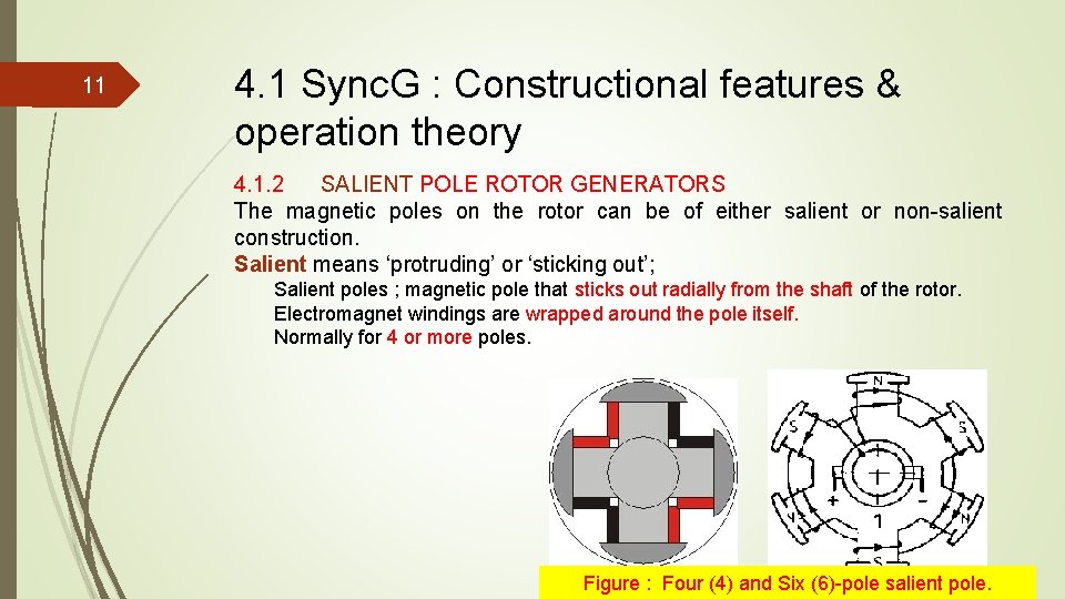
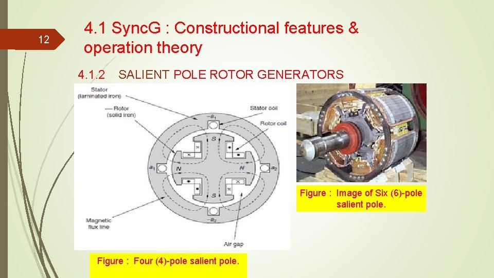
11 4. 1 Sync. G : Constructional features & operation theory 4. 1. 2 SALIENT POLE ROTOR GENERATORS The magnetic poles on the rotor can be of either salient or non-salient construction. Salient means ‘protruding’ or ‘sticking out’; Salient poles ; magnetic pole that sticks out radially from the shaft of the rotor. Electromagnet windings are wrapped around the pole itself. Normally for 4 or more poles. Figure : Four (4) and Six (6)-pole salient pole.
12 4. 1 Sync. G : Constructional features & operation theory 4. 1. 2 SALIENT POLE ROTOR GENERATORS Figure : Image of Six (6)-pole salient pole. Figure : Four (4)-pole salient pole.
Chapter 4: Synchronous machine 13 4. 1 4. 2 Sync. G : Constructional features & operation theory 4. 1. 1 Introduction 4. 1. 2 Salient pole rotor generators 4. 1. 3 Non-salient pole rotor generators 4. 1. 4 Different between Salient and Non-Salient pole generator 4. 1. 5 Principle Operation Sync. G : Basic parameter 4. 2. 1 Speed of rotation 4. 2. 2 Internal generated voltage 4. 2. 3 Equivalent circuit 4. 2. 4 Voltage regulation / Phasor diagram 4. 2. 5 Measuring model parameters 4. 3 Sync. G : Parallel operation of AC Generators 4. 4 Sync. M : Principle operation
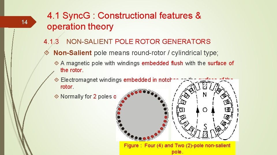
14 4. 1 Sync. G : Constructional features & operation theory 4. 1. 3 NON-SALIENT POLE ROTOR GENERATORS Non-Salient pole means round-rotor / cylindrical type; A magnetic pole with windings embedded flush with the surface of the rotor. Electromagnet windings embedded in notches on the surface of the rotor. Normally for 2 poles or 4 poles. Figure : Four (4) and Two (2)-pole non-salient pole.
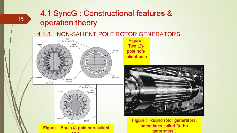
15 4. 1 Sync. G : Constructional features & operation theory 4. 1. 3 NON-SALIENT POLE ROTOR GENERATORS Figure : Two (2)pole nonsalient pole. Figure : Four (4)-pole non-salient Figure : Round rotor generators, sometimes called “turbo generators”.
Chapter 4: Synchronous machine 16 4. 1 4. 2 Sync. G : Constructional features & operation theory 4. 1. 1 Introduction 4. 1. 2 Salient pole rotor generators 4. 1. 3 Non-salient pole rotor generators 4. 1. 4 Different between Salient and Non-Salient pole generator 4. 1. 5 Principle Operation Sync. G : Basic parameter 4. 2. 1 Speed of rotation 4. 2. 2 Internal generated voltage 4. 2. 3 Equivalent circuit 4. 2. 4 Voltage regulation / Phasor diagram 4. 2. 5 Measuring model parameters 4. 3 Sync. G : Parallel operation of AC Generators 4. 4 Sync. M : Principle operation
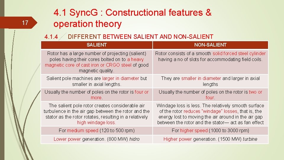
17 4. 1 Sync. G : Constructional features & operation theory 4. 1. 4 DIFFERENT BETWEEN SALIENT AND NON-SALIENT Rotor has a large number of projecting (salient) poles having their cores bolted on to a heavy magnetic core of cast iron or CRGO steel of good magnetic quality. Rotor consists of a smooth solid forced steel cylinder having a no of slots for accommodating field coils. Salient pole machines are larger in diameter but smaller in axial lengths. They are smaller in diameter and larger in axial lengths Usually the number of poles on the rotor is four or more. Usually the number of poles on the rotor is two or four. The salient pole rotor creates considerable air turbulence in the air gap between the rotor and the stator as the rotor rotates, resulting in a relatively high windage loss. Windage loss is less. The relatively smooth surface of the rotor reduces “windage” losses, that is, the energy lost to moving the air around in the air gap between the rotor and the stator— act as fan effect For medium speed (120 to 500 rpm) For higher speed (1000 to 3000 rpm) Lower power generation. (800 MW) hidro Higher power generation. (1500 MW) turbine
Chapter 4: Synchronous machine 18 4. 1 4. 2 Sync. G : Constructional features & operation theory 4. 1. 1 Introduction 4. 1. 2 Salient pole rotor generators 4. 1. 3 Non-salient pole rotor generators 4. 1. 4 Different between Salient and Non-Salient pole generator 4. 1. 5 Principle Operation Sync. G : Basic parameter 4. 2. 1 Speed of rotation 4. 2. 2 Internal generated voltage 4. 2. 3 Equivalent circuit 4. 2. 4 Voltage regulation / Phasor diagram 4. 2. 5 Measuring model parameters 4. 3 Sync. G : Parallel operation of AC Generators 4. 4 Sync. M : Principle operation
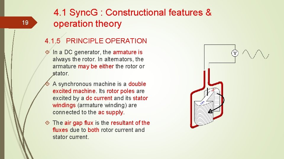
19 4. 1 Sync. G : Constructional features & operation theory 4. 1. 5 PRINCIPLE OPERATION In a DC generator, the armature is always the rotor. In alternators, the armature may be either the rotor or stator. A synchronous machine is a double excited machine. Its rotor poles are excited by a dc current and its stator windings (armature winding) are connected to the ac supply. The air gap flux is the resultant of the fluxes due to both rotor current and stator current.
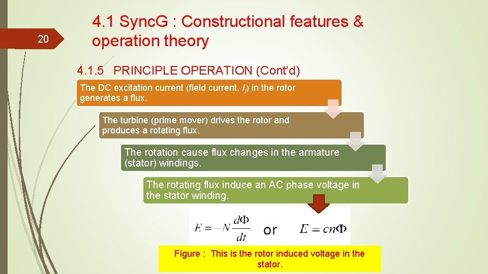
20 4. 1 Sync. G : Constructional features & operation theory 4. 1. 5 PRINCIPLE OPERATION (Cont’d) The DC excitation current (field current, If) in the rotor generates a flux. The turbine (prime mover) drives the rotor and produces a rotating flux. The rotation cause flux changes in the armature (stator) windings. The rotating flux induce an AC phase voltage in the stator winding. Figure : This is the rotor induced voltage in the stator.
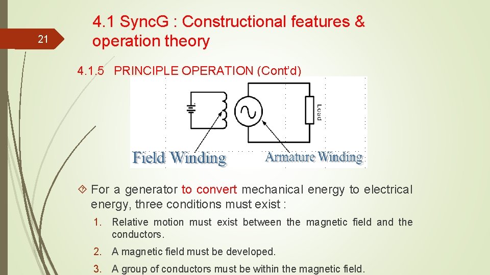
21 4. 1 Sync. G : Constructional features & operation theory 4. 1. 5 PRINCIPLE OPERATION (Cont’d) For a generator to convert mechanical energy to electrical energy, three conditions must exist : 1. Relative motion must exist between the magnetic field and the conductors. 2. A magnetic field must be developed. 3. A group of conductors must be within the magnetic field.
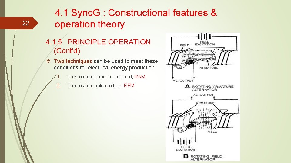
22 4. 1 Sync. G : Constructional features & operation theory 4. 1. 5 PRINCIPLE OPERATION (Cont’d) Two techniques can be used to meet these conditions for electrical energy production : 1. The rotating armature method, RAM. 2. The rotating field method, RFM.
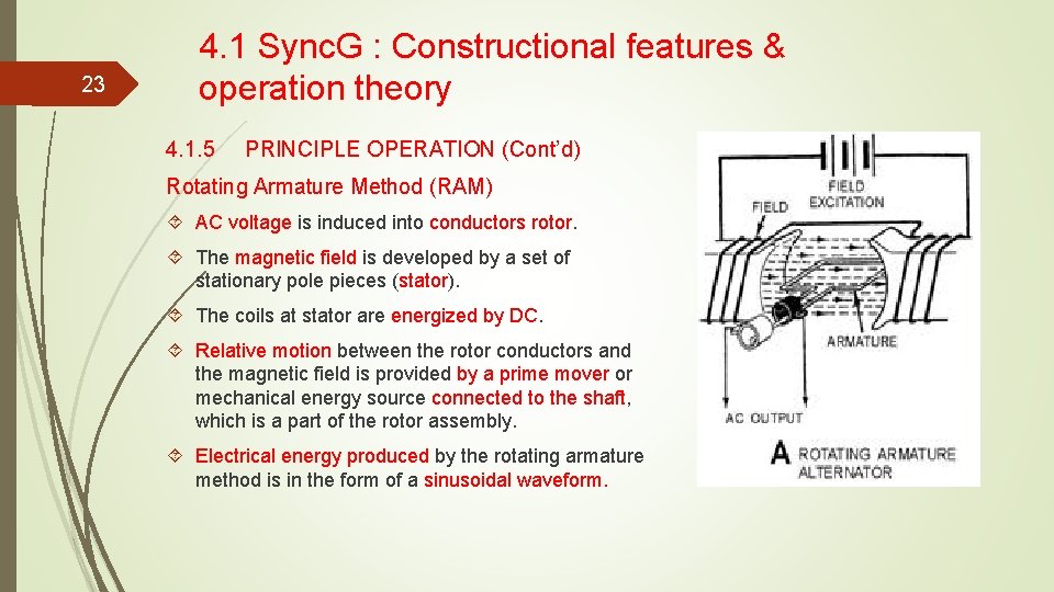
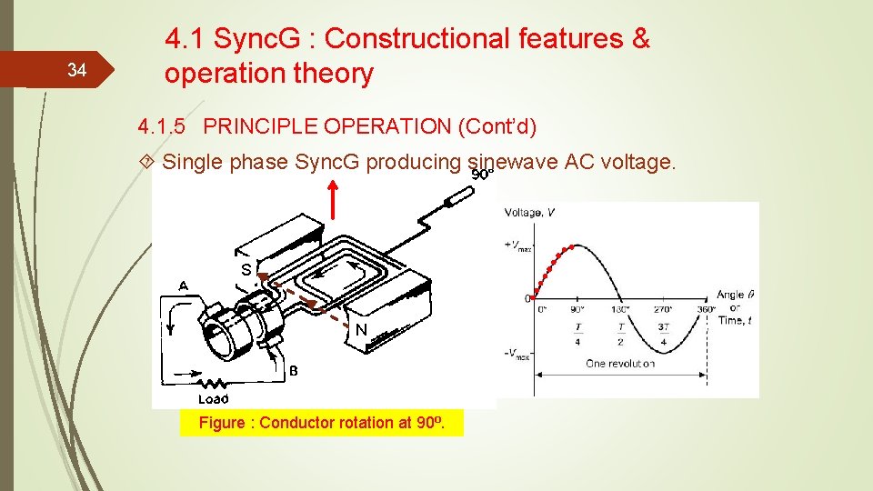
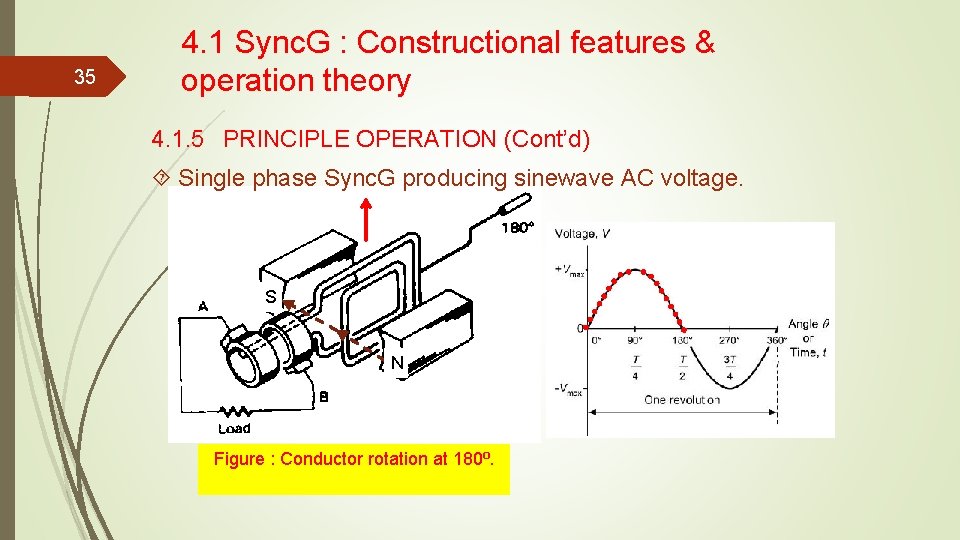
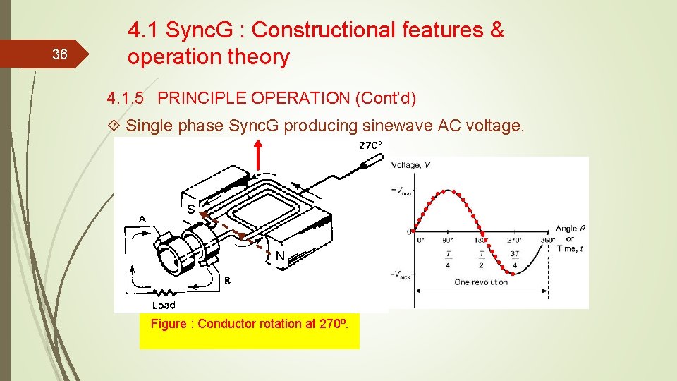
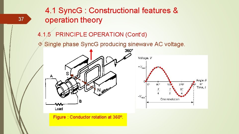
23 4. 1 Sync. G : Constructional features & operation theory 4. 1. 5 PRINCIPLE OPERATION (Cont’d) Rotating Armature Method (RAM) AC voltage is induced into conductors rotor. The magnetic field is developed by a set of stationary pole pieces (stator). The coils at stator are energized by DC. Relative motion between the rotor conductors and the magnetic field is provided by a prime mover or mechanical energy source connected to the shaft, which is a part of the rotor assembly. Electrical energy produced by the rotating armature method is in the form of a sinusoidal waveform.
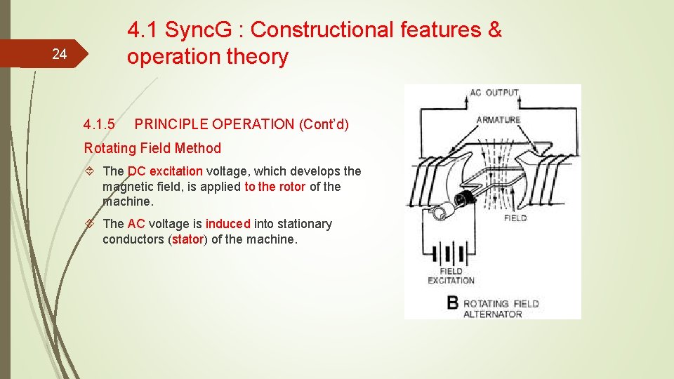
4. 1 Sync. G : Constructional features & operation theory 24 4. 1. 5 PRINCIPLE OPERATION (Cont’d) Rotating Field Method The DC excitation voltage, which develops the magnetic field, is applied to the rotor of the machine. The AC voltage is induced into stationary conductors (stator) of the machine.
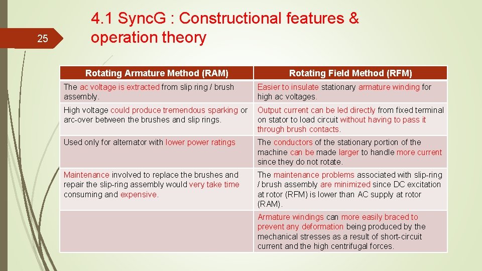
25 4. 1 Sync. G : Constructional features & operation theory Rotating Armature Method (RAM) Rotating Field Method (RFM) The ac voltage is extracted from slip ring / brush assembly. Easier to insulate stationary armature winding for high ac voltages. High voltage could produce tremendous sparking or arc-over between the brushes and slip rings. Output current can be led directly from fixed terminal on stator to load circuit without having to pass it through brush contacts. Used only for alternator with lower power ratings The conductors of the stationary portion of the machine can be made larger to handle more current since they do not rotate. Maintenance involved to replace the brushes and repair the slip-ring assembly would very take time consuming and expensive. The maintenance problems associated with slip-ring / brush assembly are minimized since DC excitation at rotor (RFM) is lower than AC supply at rotor (RAM). Armature windings can more easily braced to prevent any deformation being produced by the mechanical stresses as a result of short-circuit current and the high centrifugal forces.
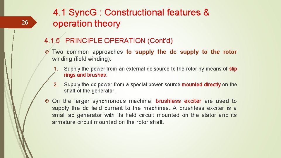
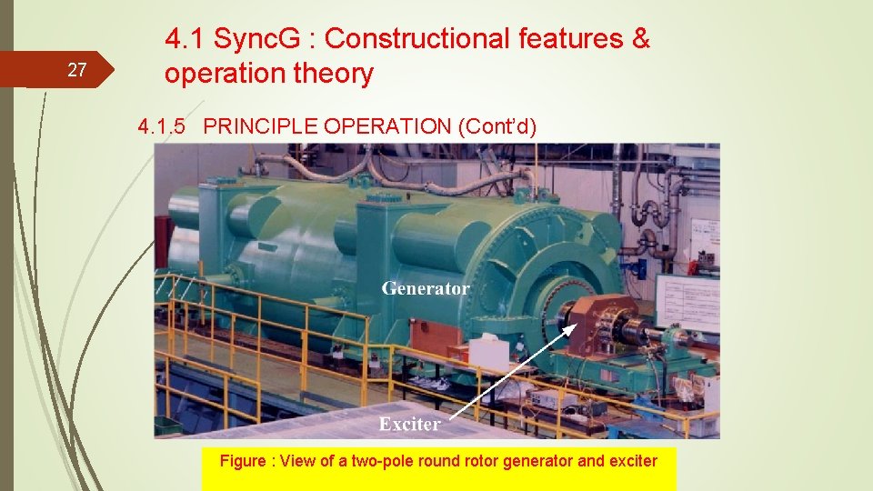
26 4. 1 Sync. G : Constructional features & operation theory 4. 1. 5 PRINCIPLE OPERATION (Cont’d) Two common approaches to supply the dc supply to the rotor winding (field winding): 1. Supply the power from an external dc source to the rotor by means of slip rings and brushes. 2. Supply the dc power from a special power source mounted directly on the shaft of the generator. On the larger synchronous machine, brushless exciter are used to supply the dc field current to the machines. A brushless exciter is a small ac generator with its field circuit mounted on the stator and its armature circuit mounted on the rotor shaft.
27 4. 1 Sync. G : Constructional features & operation theory 4. 1. 5 PRINCIPLE OPERATION (Cont’d) Figure : View of a two-pole round rotor generator and exciter
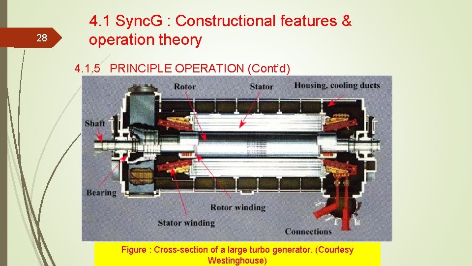
28 4. 1 Sync. G : Constructional features & operation theory 4. 1. 5 PRINCIPLE OPERATION (Cont’d) Figure : Cross-section of a large turbo generator. (Courtesy Westinghouse)
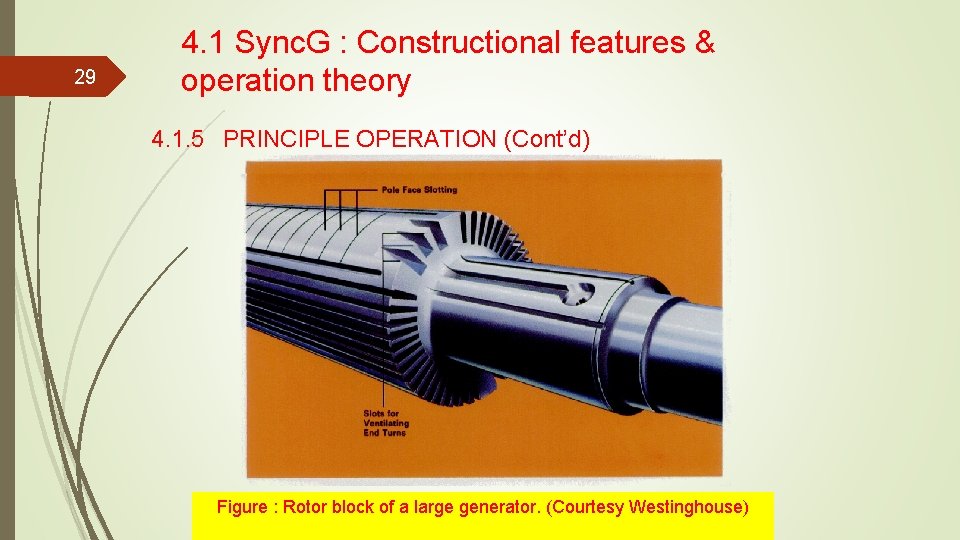
29 4. 1 Sync. G : Constructional features & operation theory 4. 1. 5 PRINCIPLE OPERATION (Cont’d) Figure : Rotor block of a large generator. (Courtesy Westinghouse)
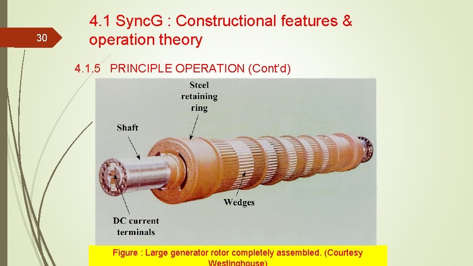
30 4. 1 Sync. G : Constructional features & operation theory 4. 1. 5 PRINCIPLE OPERATION (Cont’d) Figure : Large generator rotor completely assembled. (Courtesy
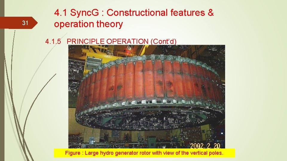
31 4. 1 Sync. G : Constructional features & operation theory 4. 1. 5 PRINCIPLE OPERATION (Cont’d) Figure : Large hydro generator rotor with view of the vertical poles.
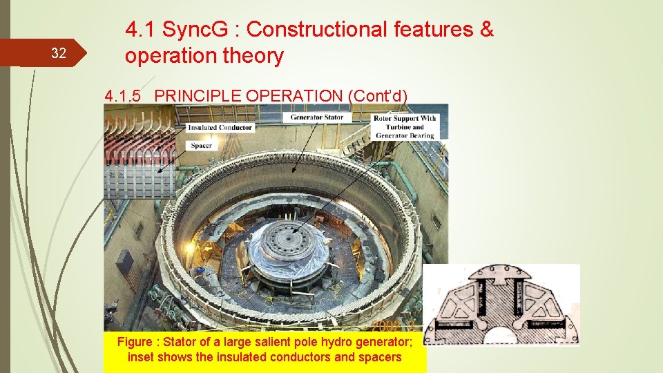
32 4. 1 Sync. G : Constructional features & operation theory 4. 1. 5 PRINCIPLE OPERATION (Cont’d) Figure : Stator of a large salient pole hydro generator; inset shows the insulated conductors and spacers
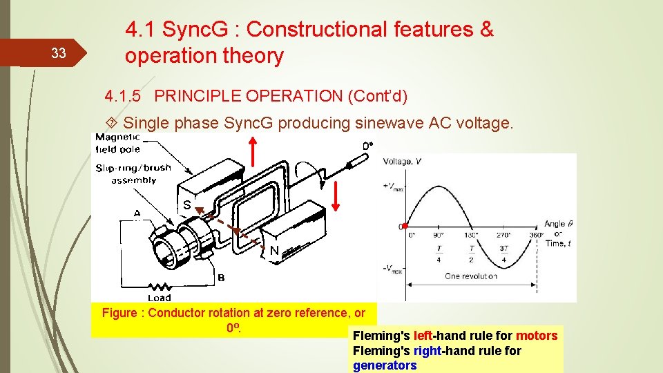
33 4. 1 Sync. G : Constructional features & operation theory 4. 1. 5 PRINCIPLE OPERATION (Cont’d) Single phase Sync. G producing sinewave AC voltage. S N Figure : Conductor rotation at zero reference, or 0⁰. Fleming's left-hand rule for motors Fleming's right-hand rule for generators
34 4. 1 Sync. G : Constructional features & operation theory 4. 1. 5 PRINCIPLE OPERATION (Cont’d) Single phase Sync. G producing sinewave AC voltage. S N Figure : Conductor rotation at 90⁰.
35 4. 1 Sync. G : Constructional features & operation theory 4. 1. 5 PRINCIPLE OPERATION (Cont’d) Single phase Sync. G producing sinewave AC voltage. S N Figure : Conductor rotation at 180⁰.
36 4. 1 Sync. G : Constructional features & operation theory 4. 1. 5 PRINCIPLE OPERATION (Cont’d) Single phase Sync. G producing sinewave AC voltage. S N Figure : Conductor rotation at 270⁰.
37 4. 1 Sync. G : Constructional features & operation theory 4. 1. 5 PRINCIPLE OPERATION (Cont’d) Single phase Sync. G producing sinewave AC voltage. S N Figure : Conductor rotation at 360⁰.
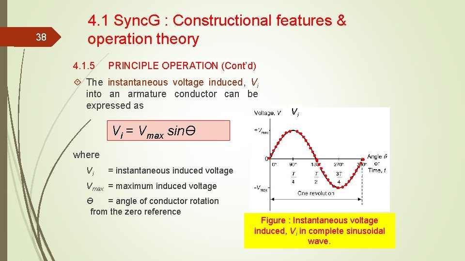
38 4. 1 Sync. G : Constructional features & operation theory 4. 1. 5 PRINCIPLE OPERATION (Cont’d) The instantaneous voltage induced, Vi into an armature conductor can be expressed as Vi Vi = Vmax sinƟ where Vi = instantaneous induced voltage Vmax = maximum induced voltage Ɵ = angle of conductor rotation from the zero reference Figure : Instantaneous voltage induced, Vi in complete sinusoidal wave.
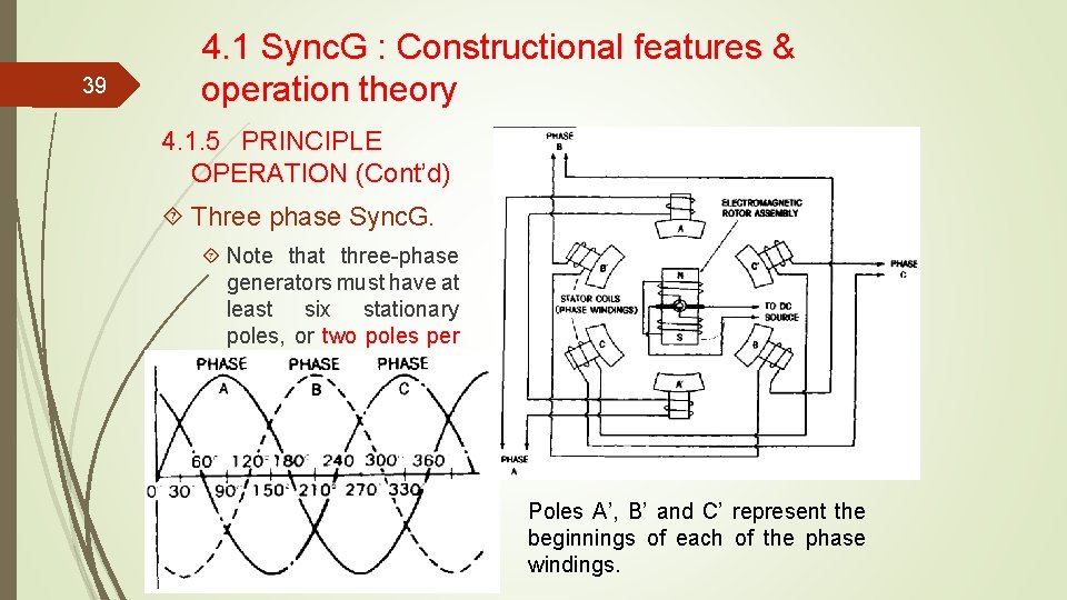
39 4. 1 Sync. G : Constructional features & operation theory 4. 1. 5 PRINCIPLE OPERATION (Cont’d) Three phase Sync. G. Note that three-phase generators must have at least six stationary poles, or two poles per phase. Poles A’, B’ and C’ represent the beginnings of each of the phase windings.
40 To be continue…