UNITIII Medium Access Control Multiple Access Broadcast link

UNIT-III Medium Access Control

Multiple Access Broadcast link used in LAN consists of multiple sending and receiving nodes connected to or use a single shared link

Data link layer divided into two functionalityoriented sublayers: Responsible for error and flow control Link Layer Control (LLC) MAC Control Responsible framing and MAC address and Multiple Access Control

Multiple Access § Problem: When two or more nodes transmit at the same time, their frames will collide and the link bandwidth is wasted during collision § How to coordinate the access of multiple sending/receiving nodes to the shared link? ? ? • Solution: We need a protocol to coordinate the transmission of the active nodes
 Protocols belong")
• These protocols are called Medium or Multiple Access Control (MAC) Protocols belong to a sublayer of the data link layer called MAC (Medium Access Control) • What is expected from Multiple Access Protocols: – Main task is to minimize collisions in order to utilize the bandwidth by: • Determining when a station can use the link (medium) • what a station should do when the link is busy • what the station should do when it is involved in collision

Taxonomy of multiple-access protocols

Channel Allocation Basic problem: How to allocate a multi-access channel among competing users. In other words, we need a set of rules (i. e. a protocol) to allow each user to communicate and avoid interference. There a variety of solutions to this problem that are used in practice. These solutions can be classified as either static or dynamic.

With a static approach, the channel's capacity is essentially divided into fixed portions; each user is then allocated a portion for all time. If the user has no traffic to use in its portion, then it goes unused.

With a dynamic approach the allocation of the channel changes based on the traffic generated by the users. Generally, a static allocation performs better when the traffic is predictable. A dynamic channel allocation tries to get better utilization and lower delay on a channel when the traffic is unpredictable.

Random Access • Also called contention-based access method. • No station is assigned to control another. • No station is superior to another station. • No station permits, or does not permit, another station to send.

Two features give this method its name. First, there is no scheduled time for a station to transmit. Transmission is random among the stations. That is why these methods are called random access. Second, no rules specify which station should send next. Stations compete with one another to access the medium. That is why these methods are also called contention methods.

ALOHA, the earliest random access method, was developed at the University of Hawaii in early 1970. It was designed for a radio (wireless) LAN, but it can be used on any shared medium. It is obvious that there are potential collisions in this arrangement. The medium is shared between the stations. When a station sends data, another station may attempt to do so at the same time. The data from the two stations collide and become garbled.

ALOHA Network

Frames in a pure ALOHA network

Pure ALOHA Protocol Description: - §All frames from any station are of fixed length (L bits) §Stations transmit at equal transmission time (all stations produce frames with equal frame lengths). §A station that has data can transmit at any time. § After transmitting a frame, the sender waits for an acknowledgment for an amount of time (time out). § If no ACK was received, sender assumes that the frame or ACK has been destroyed and resends that frame after it waits for a random amount of time.

§ If station fails to receive an ACK after repeated transmissions, it gives up. § Channel utilization or efficiency or Throughput is the percentage of the transmitted frames that arrive successfully (without collisions) or the percentage of the channel bandwidth that will be used for transmitting frames without collisions. ALOHA Maximum channel utilization is 18% (i. e, if the system produces F frames/s, then 0. 18 * F frames will arrive successfully on average without the need of retransmission).

A collision involves two or more stations. If all these stations try to resend their frames after the time-out, the frames will collide again. Pure ALOHA dictates that when the time-out period passes, each station waits a random amount of time before resending its frame. The randomness will help avoid more collisions. We call this time the back-off time TB.

Procedure for pure ALOHA Protocol

Example • Calculate possible values of TB when stations on an ALOHA network are a maximum of 600 km apart Tp = Distance/Propagation Speed Tp= (600 × 103) / (3 × 10⁸) = 2 ms • When K=1, TB {0 ms, 2 ms} • When K=2, TB {0 ms, 2 ms, 4 ms, 6 ms}

Vulnerable time for pure ALOHA protocol

If the frame transmission time is T sec, then the vulnerable time is = 2 T sec. This means no station should send during the T-sec before this station starts transmission and no station should start sending during the T-sec period that the current station is sending.

Pure ALOHA In pure ALOHA, frames are transmitted at completely arbitrary times.

Random Access – Slotted ALOHA • Pure ALOHA has a vulnerable time of 2 x Tfr. • This is so because there is no rule that defines when the station can send. • A station may send soon after another station has started or soon before another station has finished. • Slotted ALOHA was invented to improve the efficiency of pure ALOHA.
")
• Time is divided into slots equal to a frame transmission time (Tfr) • A station can transmit at the beginning of a slot only • If a station misses the beginning of a slot, it has to wait until the beginning of the next time slot. • A central clock or station informs all stations about the start of a each slot • Maximum channel utilization is 37%

Frames in a slotted ALOHA network

In danger time for slotted ALOHA protocol

Random Access – Slotted ALOHA

Advantage of ALOHA protocols A node that has frames to be transmitted can transmit continuously at the full rate of channel if it is the only node with frames n n Simple to be implemented. No master station is needed to control the medium. n
 nodes want to transmit, many collisions can occur and the rate")
Disadvantage: If (M) nodes want to transmit, many collisions can occur and the rate allocated for each node will not be on average R/M bps n n This causes low channel utilization.

CSMA § To minimize the chance of collision and, therefore, increase the performance, the CSMA method was developed. § The chance of collision can be reduced if a station senses the medium before trying to use it. § Carrier sense multiple access (CSMA) requires that each station first listen to the medium (or check the state of the medium) before sending. In other words, CSMA is based on the principle "sense before transmit" or "listen before talk”

Space/time model of the collision in CSMA
")
Random Access – Carrier Sense Multiple Access (CSMA)
 § Vulnerable time for CSMA is")
Random Access – Carrier Sense Multiple Access (CSMA) § Vulnerable time for CSMA is the maximum propagation time

Vulnerable Time : This is the time needed for a signal to propagate from one end of the medium to the other. When a station sends a frame, and any other station tries to send a frame during this time, a collision will result. But if the first bit of the frame reaches the end of the medium, every station will already have heard the bit and will refrain from sending.

Types of CSMA Protocols Different CSMA protocols that determine: § What a station should do when the medium is idle? § What a station should do when the medium is busy? 1. Non-Persistent CSMA 2. 1 -Persistent CSMA 3. p-Persistent CSMA

Nonpersistent CSMA § § A station with frames to be sent, should sense the medium 1. If medium is idle, transmit; otherwise, go to 2 2. If medium is busy, (backoff) wait a random amount of time and repeat 1 Non-persistent Stations are deferential (respect others).

§ Performance: § Random delays reduces probability of collisions because two stations with data to be transmitted will wait for different amount of times. § Bandwidth is wasted if waiting time (backoff) is large because medium will remain idle following end of transmission even if one or more stations have frames to send

Random Waiting times Wasted time

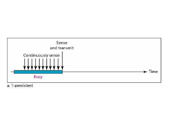
1 -persistent CSMA n n § To avoid idle channel time, 1 -persistent protocol used Station wishing to transmit listens to the medium: 1. If medium idle, transmit immediately; 2. If medium busy, continuously listen until medium becomes idle; then transmit immediately with probability 1 Performance § 1 -persistent stations are selfish. § If two or more stations becomes ready at the same time, collision guaranteed.

P-persistent CSMA n n 1. Time is divided to slots where each Time unit (slot) typically equals maximum propagation delay. Station wishing to transmit listens to the medium: If medium idle, § transmit with probability (p), OR § wait one time unit (slot) with probability (1 – p), then repeat 1.

2. If medium busy, continuously listen until idle and repeat step 1 Performance n Reduces the possibility of collisions like nonpersistent n Reduces channel idle time like 1 persistent
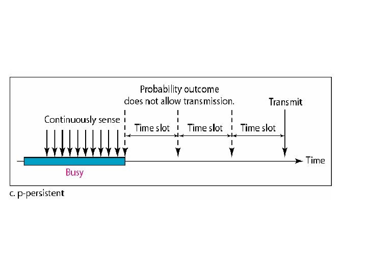

Flow diagram for three persistence methods
 has an inefficiency: § If a collision")
CSMA/CD § § CSMA (all previous methods) has an inefficiency: § If a collision has occurred, the channel is unstable until colliding packets have been fully transmitted. CSMA/CD (Carrier Sense Multiple Access with Collision Detection) overcomes this as follows:

§ § § While transmitting, the sender is listening to medium for collisions. Sender stops transmission if collision has occurred reducing channel wastage. CSMA/CD is Widely used for bus topology LANs (IEEE 802. 3, Ethernet).

of its own signal, it means collision occurred

Collision of the first bit in CSMA/CD

Collision and abortion in CSMA/CD Station monitors channel while sending a frame

CSMA/CD: Minimum Frame Size • Each frame must be large enough for a sender to detect a collision. • Worst case scenario: – "A" is transmitting – "D" starts transmitting just before A's signal arrives A Long enough to hear colliding signal from D B C D

we need a restriction on the frame size. Before sending the last bit of the frame, the sending station must detect a collision, if any, and abort the transmission. This is so because the station, once the entire frame is sent, does not keep a copy of the frame and does not monitor the line for collision detection.

Flow diagram for the CSMA/CD

Energy level during transmission, idleness, or collision

§ The level of energy in a channel can have three values: zero, normal, and abnormal. § Station that has a frame to send or is sending a frame needs to monitor the energy level to determine if the channel is idle, busy, or in collision mode.

CSMA/CA When there is no collision, the station receives one signal: its own signal. When there is a collision, the station receives two signals: its own signal and the signal transmitted by a second station. To distinguish between these two cases, the received signals in these two cases must be significantly different.

In other words, the signal from the second station needs to add a significant amount of energy to the one created by the first station. In a wireless network, much of the sent energy is lost in transmission. The received signal has very little energy. Therefore, a collision may add only 5 to 10 percent additional energy. This is not useful for effective collision detection.

We need to avoid collisions on wireless networks because they cannot be detected. Carrier sense multiple access with collision avoidance (CSMA/CA) was invented for this network. Collisions are avoided through the use of CSMA/CA's three strategies: 1. The interframe space, 2. The contention window, and 3. Acknowledgments

Timing in CSMA/CA
: First, collisions are avoided by deferring transmission even if the channel")
Interframe Space (IFS): First, collisions are avoided by deferring transmission even if the channel is found idle. When an idle channel is found, the station does not send immediately. It waits for a period of time called the interframe space or IFS.

Contention window: In CSMA/CA, if the station finds the channel busy, it does not restart the timer of the contention window; it stops the timer and restarts it when the channel becomes idle. Acknowledgment : With all these precautions, there still may be a collision resulting in destroyed data. In addition, the data may be corrupted during the transmission. The positive acknowledgment and the time-out timer can help guarantee that the receiver has received the Frame.

Flow diagram for CSMA/CA

STANDARD ETHERNET The original Ethernet was created in 1976 at Xerox’s Palo Alto Research Center (PARC). Since then, it has gone through four generations.

Ethernet evolution through four generations

802. 3 MAC frame

Preamble: - That alerts the receiving system to the coming frame and enables it to synchronize its input timing. The pattern provides only an alert and a timing pulse. The preamble is actually added at the physical layer and is not (formally) part of the frame. Start frame delimiter (SFD). The second field (l byte: 10101011) signals the beginning of the frame. The SFD warns the station or stations that this is the last chance for synchronization. The last 2 bits is 11 and alerts the receiver that the next field is the destination address.

Length or type. The original Ethernet used this field as the type field to define the upper-layer protocol using the MAC frame. The IEEE standard used it as the length field to define the number of bytes in the data field.

Minimum and maximum lengths

Example of an Ethernet address in hexadecimal notation

Physical Layer: Categories of Standard Ethernet

Encoding in a Standard Ethernet implementation All standard implementations use digital signaling at 10 Mbps

10 Base 5 implementation § 10 Base 5 , thick Ethernet or thicknet

10 Base 2 implementation

§ Cheapernet. § The cable is much thinner and more flexible. § The transceiver is normally part of the network interface card (NIC). § The collision here occurs in the thin coaxial cable. § More cost effective than 10 Base 5. § The length of each segment cannot exceed 185 m (close to 200 m) due to the high level of attenuation in thin coaxial cable.

10 Base-T implementation

§ Twisted-pair Ethernet. § The stations are connected to a hub via two pairs of twisted cable. § Two pairs of twisted cable create two paths (one for sending and one for receiving) between the station and the hub. § Replaces the coaxial cable as far as a collision is concerned. § maximum length = 100 m.

10 Base-F implementation

Summary of Standard Ethernet implementations

FAST ETHERNET Fast Ethernet was designed to compete with LAN protocols such as FDDI (Fiber Distributed Data Interface) or Fiber Channel. It is a set of ANSI and ISO standards for data transmission on fiber optic lines in a local area network (LAN) that can extend in range up to 200 km (124 miles) IEEE created Fast Ethernet under the name 802. 3 u.

Fast Ethernet is backward-compatible with Standard Ethernet, but it can transmit data 10 times faster at a rate of 100 Mbps. Goal: 1. Upgrade the data rate to 100 Mbps. 2. Make it compatible with Standard Ethernet. 3. Keep the same 48 -bit address. 4. Keep the same frame format. 5. Keep the same minimum and maximum frame lengths.

MAC Sublayer : The evolution of Ethernet from 10 to 100 Mbps. A decision was made to drop the bus topologies and keep only the star topology. For the star topology, there are two choices, half duplex and full duplex. In the half-duplex approach, the stations are connected via a hub;

In the full-duplex approach, the connection is made via a switch with buffers at each port. The access method is the same (CSMA/CD) for the half-duplex approach; For full duplex Fast Ethernet, there is no need for CSMA/CD. However, the implementations keep CSMA/CD for backward compatibility with Standard Ethernet.

Physical Layer: Fast Ethernet topology

Fast Ethernet implementations

Encoding for Fast Ethernet implementation
![1] 1 OOBase-TX uses two pairs of twisted-pair cable (either category 5 UTP or](http://slidetodoc.com/presentation_image_h/1289e3467e348acbce80d6932df03534/image-85.jpg "1] 1 OOBase-TX uses two pairs of twisted-pair cable (either category 5 UTP or")
1] 1 OOBase-TX uses two pairs of twisted-pair cable (either category 5 UTP or STP). For this implementation, the MLT-3 scheme was selected since it has good bandwidth performance MLT-3 is not a self-synchronous line coding scheme, 4 B/5 B block coding is used to provide bit synchronization by preventing the occurrence of a long sequence of Os and 1 s. This creates a data rate of 125 Mbps, which is fed into MLT-3 for encoding
![2] 1 OOBase-FX uses two pairs of fiber-optic cables. Optical fiber can easily handle](http://slidetodoc.com/presentation_image_h/1289e3467e348acbce80d6932df03534/image-86.jpg "2] 1 OOBase-FX uses two pairs of fiber-optic cables. Optical fiber can easily handle")
2] 1 OOBase-FX uses two pairs of fiber-optic cables. Optical fiber can easily handle high bandwidth requirements by using simple encoding schemes. The designers of 100 Base-FX selected the NRZ-I encoding scheme. NRZ-I has a bit synchronization problem for long sequences of Os and 1 s. To overcome this problem, the designers used 4 B/5 B block coding. The block encoding increases the bit rate from 100 to 125 Mbps, which can easily be handled by fiber-optic cable.
![3] A 1 OOBase-TX network can provide a data rate of 100 Mbps, but](http://slidetodoc.com/presentation_image_h/1289e3467e348acbce80d6932df03534/image-87.jpg "3] A 1 OOBase-TX network can provide a data rate of 100 Mbps, but")
3] A 1 OOBase-TX network can provide a data rate of 100 Mbps, but it requires the use of category 5 UTP or STP cable. A new standard, called 1 OOBase-T 4, was designed to use category 3 or higher UTP. It uses four pairs of UTP for transmitting 100 Mbps. Encoding/decoding in 100 Base-T 4 is more complicated.

It uses category 3 UTP, each twisted-pair cannot easily handle more than 25 Mbaud. In this design, one pair switches between sending and receiving. Three pairs of UTP category 3, however, can handle only 75 Mbaud (25 Mbaud) each. We need to use an encoding scheme that converts 100 Mbps to a 75 Mbaud signal. So we use 8 B/6 T satisfies this requirement. In 8 B/6 T, eight data elements are encoded as six signal elements.

Summary of Fast Ethernet implementations

GIGABIT ETHERNET The need for an even higher data rate resulted in the design of the Gigabit Ethernet protocol (1000 Mbps). The IEEE committee calls the standard 802. 3 z.

Goal: 1. Upgrade the data rate to 1 Gbps. 2. Make it compatible with Standard or Fast Ethernet. 3. Use the same 48 -bit address. 4. Use the same frame format. 5. Keep the same minimum and maximum frame lengths.

MAC Sublayer Gigabit Ethernet has two distinctive approaches for medium access: half-duplex and full-duplex. Almost all implementations of Gigabit Ethernet follow the full-duplex approach. In the full-duplex mode of Gigabit Ethernet, there is no collision; the maximum length of the cable is determined by the signal attenuation in the cable.

Half-Duplex Mode Gigabit Ethernet can also be used in half-duplex mode, although it is rare. A switch can be replaced by a hub, which acts as the common cable in which a collision might occur. The half-duplex approach uses CSMAl. CD.

Physical Layer The physical layer in Gigabit Ethernet is more complicated than that in Standard or Fast Ethernet.

Topologies of Gigabit Ethernet

Gigabit Ethernet implementations Cat-5 Twisted pair cable

Encoding in Gigabit Ethernet implementations

The two-wire implementations use an NRZ scheme, but NRZ does not self-synchronize properly. To synchronize bits, particularly at this high data rate, 8 B/10 B block encoding, is used. This block encoding prevents long sequences of 0 s or 1 s in the stream, but the resulting stream is 1. 25 Gbps. In this implementation, one wire (fiber or STP) is used for sending and one for receiving.

In the four-wire implementation it is not possible to have 2 wires for input and 2 for output, because each wire would need to carry 500 Mbps, which exceeds the capacity for category 5 UTP. As a solution, 4 D-PAM 5 encoding is used to reduce the bandwidth. Thus, all four wires are involved in both input and output; each wire carries 250 Mbps, which is in the range for category 5 UTP cable.

Summary of Gigabit Ethernet implementations

IEEE 802. 11 wireless LANs Wireless communication is one of the fastestgrowing technologies. The demand for connecting devices without the use of cables is increasing everywhere. Wireless LANs can be found on college campuses, in office buildings, and in many public areas. we concentrate on two promising wireless technologies for LANs: IEEE 802. 11 wireless LANs, sometimes called wireless Ethernet, and Bluetooth, a technology for small wireless LANs.

IEEE 802. 11 wireless LANs : IEEE has defined the specifications for a wireless LAN, called IEEE 802. 11, which covers the physical and data link layers.

MAC Sublayer MAC layers in IEEE 802. 11 standard
 sublayer provides multiplexing mechanisms that make it possible for several")
The logical link control(LLC) sublayer provides multiplexing mechanisms that make it possible for several network protocols. It can also provide flow control and automatic repeat request(ARQ) error management mechanisms. The LLC sublayer acts as an interface between the media access control (MAC) sublayer and the network layer.
![I] Distributed Coordination Function: -(DCF) One of the two protocols defined by IEEE at](http://slidetodoc.com/presentation_image_h/1289e3467e348acbce80d6932df03534/image-105.jpg "I] Distributed Coordination Function: -(DCF) One of the two protocols defined by IEEE at")
I] Distributed Coordination Function: -(DCF) One of the two protocols defined by IEEE at the MAC sublayer is called the distributed coordination function (DCF). DCF uses CSMA/CA as the access method. Wireless LANs cannot implement CSMA/CD
![II] Point Coordination Function (PCF): The point coordination function (PCF) is an optional access](http://slidetodoc.com/presentation_image_h/1289e3467e348acbce80d6932df03534/image-106.jpg "II] Point Coordination Function (PCF): The point coordination function (PCF) is an optional access")
II] Point Coordination Function (PCF): The point coordination function (PCF) is an optional access method that can be implemented in an infrastructure network (not in an ad hoc network). It is implemented on top of the DCF and is used mostly for time-sensitive transmission. PCF has a centralized, contention-free polling access method. The AP performs polling for stations that are capable of being polled. The stations are polled one after another, sending any data they have to the AP.

Frame format in MAC layer

Subfields in FC field

D: - In all frame types except one, this field defines the duration of the transmission that is used to set the value of NAV (Network Allocation Vector). Sequence control: - This field defines the sequence number of the frame to be used in flow control.

Frame body: This field, which can be between 0 and 2312 bytes, contains information based on the type and the subtype defined in the FC field. FCS: The FCS field is 4 bytes long and contains a CRC-32 error detection sequence.

Frame Types: A wireless LAN defined by IEEE 802. 11 has three categories of frames: 1] Management frames, 2] Control frames, and 3] Data frames.
![1] Management frames: Management frames are used for the initial communication between stations and](http://slidetodoc.com/presentation_image_h/1289e3467e348acbce80d6932df03534/image-112.jpg "1] Management frames: Management frames are used for the initial communication between stations and")
1] Management frames: Management frames are used for the initial communication between stations and access points. 2] Control Frames: Control frames are used for accessing the channel and acknowledging frames.

Control frames
![3] Data Frames: Data frames are used for carrying data and control information.](http://slidetodoc.com/presentation_image_h/1289e3467e348acbce80d6932df03534/image-114.jpg "3] Data Frames: Data frames are used for carrying data and control information.")
3] Data Frames: Data frames are used for carrying data and control information.

Comparisons between Ethernet LANs and Wireless Network Ethernet 1. IEEE standard 802. 3 2. Communication Medium is coaxial cable. 3. Use MAC 4. Uses CDMA/CD 5. Efficiency is high 6. Large range Wireless Network 1. IEEE standard 802. 11 2. Infrared or radio frequencies act as medium. 3. Use two MAC Sublayer 4. Uses CDMA/CA 5. Efficiency is low 6. Short range

WLAN Standards Feature Year ratified Maximum speed using DSSS 802. 11 a 1999 — 802. 11 b 1999 11 Mbps 802. 11 g 2003 11 Mbps Maximum speed using OFDM 54 Mbps — 54 Mbps Frequency band 5 GHz 2. 4 GHz Channels (no overlapped)* 23 (12) 11 (3) 6, 12, 24 1, 2, 5. 5, 11 6, 12, 24 Speeds required by standard (Mbps)

Differences between IEEE 802. 11? IEEE 802. 11 b IEEE 802. 11 a IEEE 802. 11 g 2. 4 G Hz 5 G Hz 2. 4 G Hz Transmission Rate 1~2 Mbps 1~11 Mbps Modulation Technique FHSS/DSSS Frequency 6~54 Mbps 22~54 Mbps OFDM PBCC-22 + CCK-OFDM

Physical layers Where FHSS: -Frequency hopping spread spectrum DSSS: -Direct sequence spread spectrum OFDM: - Orthogonal Frequency-Division Multiplexing.

The 802. 11 a , 802. 11 b/g/n , and/or 802. 11 ac wireless standards collectively known as Wi-Fi technologies. ( Bluetooth and various other wireless).
![1] 802. 11: In 1997, the Institute of Electrical and Electronics Engineers (IEEE) created](http://slidetodoc.com/presentation_image_h/1289e3467e348acbce80d6932df03534/image-120.jpg "1] 802. 11: In 1997, the Institute of Electrical and Electronics Engineers (IEEE) created")
1] 802. 11: In 1997, the Institute of Electrical and Electronics Engineers (IEEE) created the first WLAN standard. They called it 802. 11 after the name of the group formed to oversee its development. Unfortunately, 802. 11 only supported a maximum network bandwidth of 2 Mbps - too slow for most applications. For this reason, ordinary 802. 11 wireless products are no longer manufactured.

Physical layer of IEEE 802. 11 FHSS FSK: -Frequency shift keying

SPREAD SPECTRUM: Multiplexing combines signals from several sources to achieve bandwidth efficiency; the available bandwidth of a link is divided between the sources. In spread spectrum (SS), we also combine signals from different sources to fit into a larger bandwidth, but our goals are somewhat different. To achieve these goals, spread spectrum techniques add redundancy.

They spread the original spectrum needed for each station. If the required bandwidth for each station is B, spread spectrum expands it to Bss' such that Bss » B. The expanded bandwidth allows the source to wrap its message in a protective envelope for a more secure transmission.

Physical layer of IEEE 802. 11 DSSS BPSK: -Binary phase shift keying. QPSK: -Quadrature Phase Shift Keying.
 technique also expands the bandwidth of the original")
The direct sequence spread spectrum (DSSS) technique also expands the bandwidth of the original signal, but the process is different. In DSSS, we replace each data bit with n bits using a spreading code. In other words, each bit is assigned a code of n bits, called chips, where the chip rate is n times that of the data bit.
![2] 802. 11 b: IEEE expanded on the original 802. 11 standard in July](http://slidetodoc.com/presentation_image_h/1289e3467e348acbce80d6932df03534/image-126.jpg "2] 802. 11 b: IEEE expanded on the original 802. 11 standard in July")
2] 802. 11 b: IEEE expanded on the original 802. 11 standard in July 1999, creating the 802. 11 b specification. 802. 11 b supports bandwidth up to 11 Mbps, comparable to traditional Ethernet. 802. 11 b uses the same unregulated radio signaling frequency (2. 4 GHz) as the original 802. 11 standard.

Vendors often prefer using these frequencies to lower their production costs. Pros of 802. 11 b - lowest cost; signal range is good and not easily obstructed. Cons of 802. 11 b - slowest maximum speed; home appliances may interfere on the unregulated frequency band.
![3] 802. 11 a While 802. 11 b was in development, IEEE created a](http://slidetodoc.com/presentation_image_h/1289e3467e348acbce80d6932df03534/image-128.jpg "3] 802. 11 a While 802. 11 b was in development, IEEE created a")
3] 802. 11 a While 802. 11 b was in development, IEEE created a second extension to the original 802. 11 standard called 802. 11 a. Because 802. 11 b gained in popularity much faster than did 802. 11 a, some folks believe that 802. 11 a was created after 802. 11 b. In fact, 802. 11 a was created at the same time. Due to its higher cost, 802. 11 a is usually found on business networks whereas 802. 11 b better serves the home market.

802. 11 a supports bandwidth up to 54 Mbps and signals in a regulated frequency spectrum around 5 GHz. Because 802. 11 a and 802. 11 b utilize different frequencies, the two technologies are incompatible with each other. Pros of 802. 11 a - fast maximum speed; regulated frequencies prevent signal interference from other devices. Cons of 802. 11 a - highest cost; shorter range signal that is more easily obstructed.
![4] 802. 11 g In 2002 and 2003, WLAN products supporting a newer standard](http://slidetodoc.com/presentation_image_h/1289e3467e348acbce80d6932df03534/image-130.jpg "4] 802. 11 g In 2002 and 2003, WLAN products supporting a newer standard")
4] 802. 11 g In 2002 and 2003, WLAN products supporting a newer standard called 802. 11 g emerged on the market. 802. 11 g attempts to combine the best of both 802. 11 a and 802. 11 b. 802. 11 g supports bandwidth up to 54 Mbps , and it uses the 2. 4 GHz frequency for greater range.

802. 11 g is backwards compatible with 802. 11 b, meaning that 802. 11 g access points will work with 802. 11 b wireless network adapters and vice versa. Pros of 802. 11 g - fast maximum speed; signal range is good and not easily obstructed. Cons of 802. 11 g - costs more than 802. 11 b; appliances may interfere on the unregulated signal frequency.
![5] 802. 11 n: 802. 11 n (also sometimes known as " Wireless N](http://slidetodoc.com/presentation_image_h/1289e3467e348acbce80d6932df03534/image-132.jpg "5] 802. 11 n: 802. 11 n (also sometimes known as \" Wireless N")
5] 802. 11 n: 802. 11 n (also sometimes known as " Wireless N ") was designed to improve on 802. 11 g in the amount of bandwidth supported by utilizing multiple wireless signals and antennas. Industry standards groups ratified 802. 11 n in 2009 with specifications providing for up to 300 Mbps of network bandwidth.

802. 11 n also offers somewhat better range over earlier Wi-Fi standards due to its increased signal intensity, and it is backward-compatible with 802. 11 b/g gear. Pros of 802. 11 n - fastest maximum speed and best signal range; more resistant to signal interference from outside sources. Cons of 802. 11 n - standard is not yet finalized; costs more than 802. 11 g; the use of multiple signals may greatly interfere with nearby 802. 11 b/g based networks.

BLUETOOTH: - IEEE 802. 15 Standard Bluetooth is a wireless LAN technology designed to connect devices of different functions such as telephones, notebooks, computers, cameras, printers, coffee makers, and so on. A Bluetooth LAN is an ad hoc network, which means that the network is formed spontaneously.

Bluetooth technology is the implementation of a protocol defined by the IEEE 802. 15 standard. The standard defines a wireless personal-area network (PAN) operable in an area the size of a room or a hall. Architecture : - Bluetooth defines two types of networks: piconet and scatternet.

Piconet

§ Small net. § A piconet can have up to eight stations. § All the secondary stations synchronize their clocks and hopping sequence with the primary. § The communication between the primary and the secondary can be one-to-one or one-tomany.

Scatternet

Piconets can be combined to form what is called a scatternet. A secondary station in one piconet can be the primary in another piconet. This station can receive messages from the primary in the first piconet (as a secondary) and, acting as a primary, deliver them to secondaries in the second piconet. A station can be a member of two piconets.

Bluetooth Devices A Bluetooth device has a built-in short-range radio transmitter. The current data rate is 1 Mbps with a 2. 4 -GHz bandwidth. This means that there is a possibility of interference between the IEEE 802. 11 b wireless LANs and Bluetooth LANs.

Frame format types

Access code. This 72 -bit field normally contains synchronization bits and the identifier of the primary to distinguish the frame of one piconet from another. Header. subfields: 1. Address. The 3 -bit address subfield can define up to seven secondaries (1 to 7). If the address is zero, it is used for broadcast communication from the primary to all secondaries.
, it indicates")
F. This 1 -bit subfield is for flow control. When set (1), it indicates that the device is unable to receive more frames (buffer is full). A. This 1 -bit subfield is for acknowledgment. Bluetooth uses Stop-and-Wait ARQ; 1 bit is sufficient for acknowledgment. S. This 1 -bit subfield holds a sequence number. Bluetooth uses Stop-and-Wait ARQ; 1 bit is sufficient for sequence numbering. HEC. The 8 -bit header error correction subfield is a checksum to detect errors in each 18 -bit header section.

Payload. This subfield can be 0 to 2740 bits long. It contains data or control information coming from the upper layers.

Binary Exponential Backoff Algorithm § Binary exponential backoff refers to a collision resolution mechanism used in random access MAC protocols. § This algorithm is used in Ethernet (IEEE 802. 3) wired LANs. In Ethernet networks, this algorithm is commonly used to schedule retransmissions after collisions.

Definitions of the components/Keywords: • After a collision, time is divided into discrete slots whose length is equal to 2τ, where τ is the maximum propagation delay in the network. • The reason for this choice is that 2τ is the minimum amount of time a source needs to listen to the channel to always detect a collision. • After 16 collisions , the process is aborted and the source stops trying.

Flow diagram for the CSMA/CD

• The stations involved in the collision randomly pick an integer from the set {0, 1}. This set is called the contention window. • If the sources collide again because they picked the same integer, the contention window size is doubled and it becomes {0, 1, 2, 3}. Now the sources involved in the second collision randomly pick an integer from the set {0, 1, 2, 3} and wait that number of slot times before trying again.
")
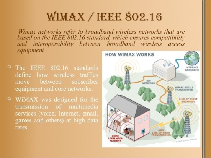
IEEE 802. 16 Wireless MAN (Wireless Metropolitan Network)

802. 16 family of standards is officially called Wireless MAN in IEEE, it has been commercialized under the name "Wi. MAX" (from "Worldwide Interoperability for Microwave Access") by the Wi. MAX Forum industry alliance.

802. 16 Architecture and Protocol Stack The 802. 16 protocol stack

802. 16 Physical Layer Frames structure for OFDMA with time division duplexing.

802. 16 MAC Sublayer Protocol Classes of service 1. Constant bit rate service. 2. Real-time variable bit rate service. 3. Non-real-time variable bit rate service. 4. Best-effort service.
 A generic frame. (b) A bandwidth request frame.")
802. 16 Frame Structure (a) A generic frame. (b) A bandwidth request frame.

- Slides: 156