UNIT I SYNCHRONOUS GENERATOR Constructional details Types of


 The High Voltage ac winding and")

 Salient Pole type {Projected Poles} ii)")


 NON SALIENT POLE TYPE Smooth cylindrical rotor or TURBO ALTERNATOR field winding used")


 β β E in coil 1 E in")
 E A")

 Armature Leakage Reactance")
 Three major components -Slot leakage reactance, end winding leakage reactance and")

 cross magnetizing Main Flux Φf N Armature Flux Φa S")
 Demagnetizing Main Flux Φf N Ia Armature Flux Φa")
 Magnetizing Main Flux Φf N S Armature Flux Φa")


SC (Voc)ph D Full Load Iasc E OCC C SCC B O A field")
2 + (Xs)2 Xs Xs = √(Zs)2 -")


 This method of determining the regulation of an alternator")


 or Potier method This method is also called")
 and armature reaction (MMF) separately, two tests are")
 Rated Terminal Voltage at Full load Current at Zero")
 The")
 Load induced EMF calculated as was done in")

 �The field currents If 1")


 connected with the Bus Bar and Supplying power to")


- Slides: 83
UNIT I SYNCHRONOUS GENERATOR Constructional details – Types of rotors – EMF equation – Synchronous reactance – Armature reaction – Voltage regulation: EMF, MMF, ZPF and ASA methods – Synchronizing and parallel operation – Synchronizing torque – Change of excitation and mechanical input – Two reaction theory – Determination of direct and quadrature axis synchronous reactance using slip test – Operating characteristics – Capability curves.
UNIT – I SYNCHRONOUS GENERATOR AC Machines Synchronous Machines Synchronous Generator A primary source of electrical energy Synchronous Motor Used as motors as well as power factor compensators (synchronous condensers) Asynchronous Machines (Induction Machine) Induction Generator Due to lack of a separate field excitation, these machines are rarely used as generators. Induction Motor Most widely used electrical motors in both domestic and industrial applications
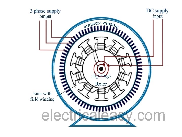
SYNCHRONOUS GENERATOR Types of Synchronous Machine According to the arrangement of the field and armature windings, synchronous machines may be classified as (a) Stationary Armature - Rotating Field (Above 5 k. VA) (b) Stationary Field – Rotating Armature (Below 5 k. VA)
Advantages of stationary armature - rotating field: i) The High Voltage ac winding and its insulation not subjected to centrifugal forces. (11 k. V - 33 k. V) (BETTER INSULATION) ii) Easier to collect large currents from a stationary member. iii) Rotating field makes overall construction simple. iv) Problem of sparking at the slip ring can be avoided. v) Ventilation arrangement for HV can be Improved. vi) The LV(110 V – 220 V) dc excitation easily supplied through slip rings and brushes to the rotor field winding. vii) Noiseless running is possible. viii)Air gap length is uniform ix) Better mechanical balancing of rotor
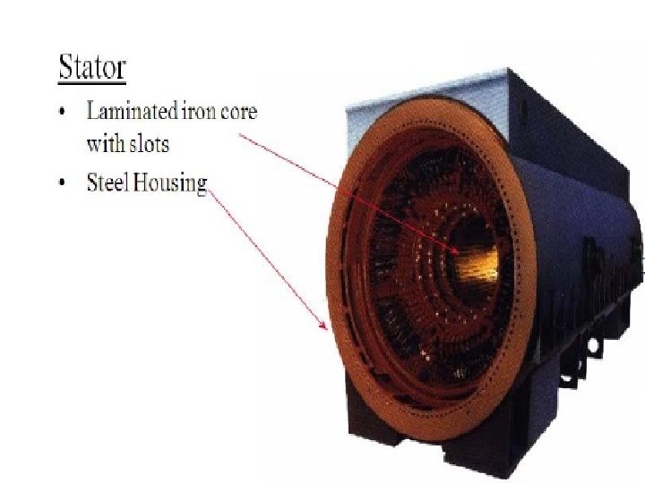
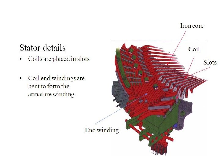
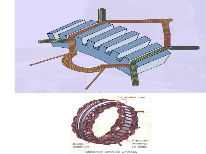
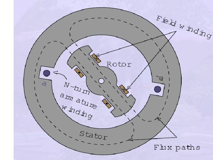
CONSTRUCTION OF ALTERNATOR Stationary Armature - Rotating Field An alternator has 3 phase winding on the stator and DC field winding on the rotor. STATOR Stationary part of the machine. It is built up of Sheet-Steel Lamination Core (Stampings) with slots to hold the armature Conductor Armature winding is connected in STAR
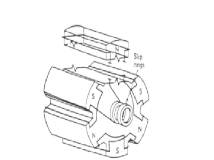
ROTOR: There are two types of rotor i) Salient Pole type {Projected Poles} ii) Non - Salient Pole type {Non – Projected Poles} Smooth Cylindrical Type
Salient Pole type {Projected Poles} It is also called Projected Poles are mounted on the larger circular frame. Made up of Thick Steel Laminations. Field Winding are connected in series. Ends of the field winding are connected to the DC Supply through Slip Rings Features Large Diameter and short Axial Length. Poles are Laminated to reduced Eddy Current Losses Employed for Low and Medium Speed 120 RMP to 500 RPM (Diesel & Hydraulic Turbines) This cannot be used for Large speed
DAMPER WINDING Pole faces are provided with damper winding Damper winding is useful in preventing Hunting EMF generated will be sinusoidal Copper Bar
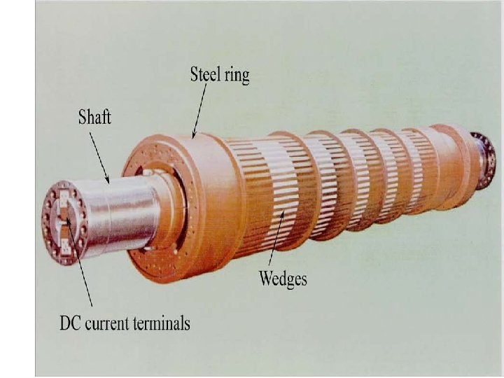
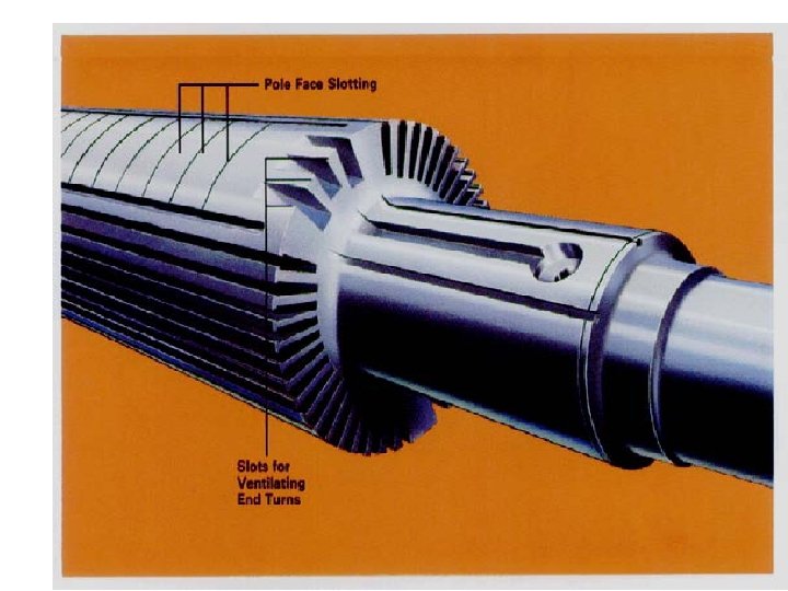
II) NON SALIENT POLE TYPE Smooth cylindrical rotor or TURBO ALTERNATOR field winding used in high speed alternators driven by steam turbines. Features Smaller diameter and larger axial length compared to salient pole type machines, of the same rating. Less Windage loss. Speed 1200 RPM to 3000 RPM. . Better Balancing. . Noiseless Operation Flux distribution nearly sine wave Frequency 50 Hz Ns = 120 F / P Poles 2 4 6 Speed 3000 1500 1000
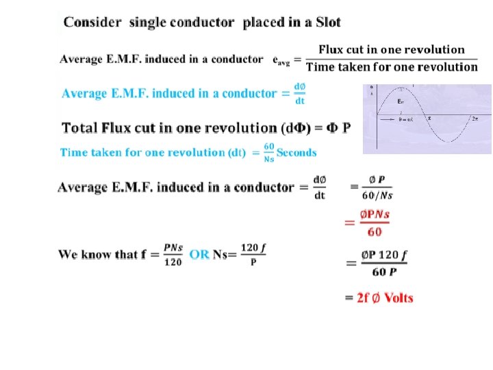
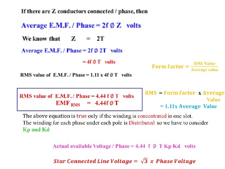
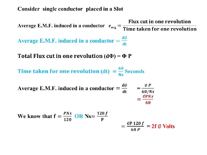
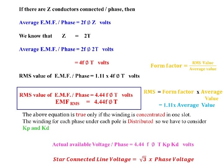
f = PNs/120, EMF Equation of an Alternator Let Φ Φ = Flux per pole, Wb P = Number of Poles Ns = Synchronous Speed in RMP Z = Total Number of Conductors or coil sides in series / Phase Z = 2 T T = Number of coils or Turns per phase Tph = Turns in series per phase = ( No. of slots * No. of cond. per slot) / (2 x 3) Zph = Conductor per phase Zph = Z / 3. No. of phase 3 Kc or Kp = Pitch factor or coil span factor Kd = Distribution factor Kp = Cos (α / 2 ) Kd = Sin (mβ / 2) m Sin(β / 2) = flux per po T
ARMATURE WINDING 3 Phase alternator carry 3 sets of winding arranged in slots Open circuited 6 terminals Can be connected in Star or Delta Armature Winding Classification 1. Single Layer and Double Layer Winding 2. Full Pitch and Short Pitch Winding 3. Concentrated and Distributed Winding
Single Layer and Double Layer Winding Single- layer winding • One coil-side occupies the total slot area • Used only in small ac machines Double- layer winding • Coil-sides in two layers • Double-layer winding is more common used above about 5 k. W machines The advantages of double-layer winding over single layer winding: a. Easier to manufacture and lower cost of the coils b. Fractional-slot winding can be used c. Chorded-winding is possible d. Lower-leakage reactance and therefore , better performance of the machine e. Better emf waveform in case of generators
POLE – PITCH It is the distance between the centres of pole faces of two adjacent poles is called pole pitch. Pole pitch = 180 Phase angle COIL : A coil consists of two coil sides. Placed in two separate slots SLOT PITCH: It is the phase angle between two adjustment slots COIL SPAN OR COIL PITCH It is the distance between two coil sides of a coil
Full Pitch and Short Pitch Winding Full Pitch Winding If the coil span is equal to pole pitch then the winding is called Full Pitch Winding Coil Span = Pole Pitch e 1 V e 2 V Short Pitch Winding If the coil span is less than Pole Pitch is called Short pitch winding e 2 V e 1 V e 2 V
Advantages of Short Chorded winding or Chorded Pitch Winding 1. Copper is saved 2. Mechanical strength of the coil is increased 3. Induced EMF in improved Slot Angle : The angular displacement between any two adjacent poles in electrical degree Slot angle (β) = 180 (Number of slots / Pole) CONCENTRATED AND DISTRIBUTED WINDING
PITCH FACTOR OR COIL SPAN FACTOR OR SHORT CHORDED FACTOR Kp OR Kc Pitch factor is defined as the ratio EMF induced in the Short pitch winding to the EMF induced in the full pitch winding Vector Sum EMF = AB = AC + CB Kp = AC + CB AD + DB B C A α/2 α α/2 E V D 2 E E V AD = BD E V Kp = Cos (α / 2)
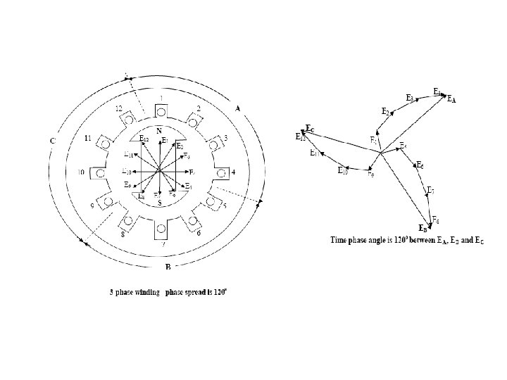
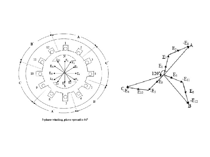
DISTRIBUTION FACTOR OR BREATH FACTOR (Kd) β β E in coil 1 E in coil 2 E in coil 3
B C e 2 r x e 1 β e 3 m(β/2) E A β r D β β/2 O mβ Vector Sum
Arithmetic Sum of EMF = AB + BC + CD From Vector diagram AB = Ax + x. B = r Sin (β/2) + r Sin (β/2) AB = 2 r Sin (β/2) Arithmetic Sum of EMF = 3 x (2 r Sin (β/2) ) AB = BC = CD = 2 r Sin (β/2) If there are ‘m’ slots for distribution, then Arithmetic Sum /phase of the EMF = m x (2 r Sin (β/2) ) Vector Sum of EMF AD = AE + ED Vector Sum of EMF AE = ED = r Sin (mβ/2) Vector Sum of EMF = 2 r x (Sin (mβ/2))
Causes of Voltage drop in Alternator Armature Effective Resistance (Reff ) Armature Leakage Reactance (XL ) Armature Reactance
Armature Leakage Reactance(XL) Three major components -Slot leakage reactance, end winding leakage reactance and tooth tip leakage reactance. Synchronous reactance / phase Xs = XL + Xa , where Xa is the fictitious armature reaction reactance. Synchronous impedance/phase Zs = (Ra + j. Xs).
Armature Reaction Effect of the armature flux on the main field flux. Armature Reaction effect depends upon the PF of the Load UPF - cross magnetizing. Lag PF - demagnetizing. Lead PF - magnetizing
UPF (Pure Resistive Load) cross magnetizing Main Flux Φf N Armature Flux Φa S Main Flux Φf Iaph Φa Eph Induced EMF due to Main Flux Φf
Lagging PF (Purely Inductive Load) Demagnetizing Main Flux Φf N Ia Armature Flux Φa Armature Flux Φa S Main Flux Φf Load current Lag the Voltage by 90 Main Flux Decreases DC excitation Eph Induced EMF due to Main Flux Φf
Lead PF (Purely Capacitive Load) Magnetizing Main Flux Φf N S Armature Flux Φa Load current Lead the Voltage by 90 Armature Flux Φa Main Flux Φf Ia Main Flux Increases DC excitation Eph Induced EMF due to Main Flux Φf
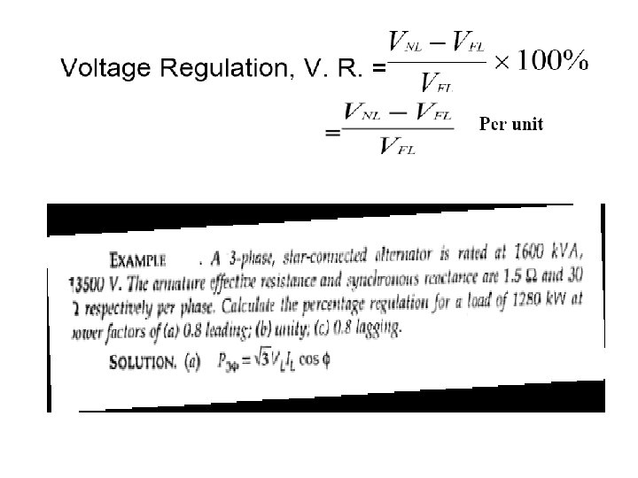
VOLTAGE REGULATION Voltage Regulation of an alternator is defined as the change in terminal voltage from NO load to full load divided by full-load voltage. % Voltage Regulation = E 0 – V x 100 V There are different methods available to determine the voltage regulation of an alternator, 1. Direct loading method 2. Synchronous impedance method or E. M. F. method 3. Ampere-turns method or M. M. F. method 4. Zero power factor method or Potier triangle method 5. ASA modified from of M. M. F. method 6. Two reaction theory
Direct loading method
The star connected armature is to be connected to a three phase load The field winding is excited by separate d. c. supply. To control the flux i. e. the current through field winding, a rheostat is inserted in series with the field winding. The prime mover drives the alternator at its synchronous speed. Eph α Φ . . . (From e. m. f. equation) For high capacity alternators, that much full load can not be simulated or directly connected to the alternator. Hence method is restricted only for small capacity alternators.
Synchronous Impedance Method or E. M. F. Method
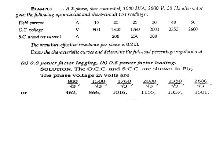
The method is also called E. M. F. method The method requires following data to calculate the regulation. 1. The armature resistance per phase (Ra). 2. Open circuit characteristics which is the graph of open circuit voltage against the field current. This is possible by conducting open circuit test on the alternator. 3. Short circuit characteristics which is the graph of short circuit current against field current. This is possible by conducting short circuit test on the alternator. Zs is calculated. Ra measured and Xs obtained. For a given armature current and power factor, Eph determined - regulation is calculated.
(Ia)SC (Voc)ph D Full Load Iasc E OCC C SCC B O A field current. If in Amps
Synchronous Impedance Regulation Calculation Zs = √(Ra)2 + (Xs)2 Xs Xs = √(Zs)2 - (Ra)2 Eph = √ (Vph Cos Φ + Ia Ra)2 + (Vph Sin Φ ± Ia Xs)2
Phasor Diagram of a loaded Alternator C Unity PF Load Eph Ia. Xs Ia. ZS O Ia Reference as Voltage (V) OA – Vph AB – Ia. Ra BC – Ia. Xs AC – Ia. Zs OC – Eph Vph A Ia. Ra B Consider Δ OBC (OC)2 = (OB)2 + (BC)2 (Eph)2 = (OA + AB)2 + (BC) 2 (Eph)2 = (Vph + Ia. Ra)2 + (Ia. Xs) 2 Eph = √ (Vph + Ia. Ra)2 + (Ia. Xs) 2
Phasor Diagram of a loaded Alternator C Lagging PF Load Eph Vph Φ O Vph Cos Φ Ia. ZS Ia. Ra Ia. Xs Vph Sin Φ Ia A Ia. Ra B Eph = √ (Vph Cos Φ + Ia Ra)2 + (Vph Sin Φ + Ia Xs)2
Phasor Diagram of a loaded Alternator Leading PF Load C Ia. ZS Eph Vph Ia. Xs Ia. Ra Φ O Ia A B Eph = √ (Vph Cos Φ + Ia Ra)2 + (Vph Sin Φ - Ia Xs)2
Advantages of Synchronous Impedance Method The main advantages of this method is the value of synchronous impedance Zs for any load condition can be calculated. Regulation of the alternator at any load condition and load power factor can be determined. Actual load need not be connected to the alternator This method can be used for very high capacity alternators Limitations of Synchronous Impedance Method The main limitation of this method is that this method gives large values of synchronous reactance. This leads to high values of percentage regulation than the actual results. Hence this method is called pessimistic method.
MMF method (Ampere turns method) This method of determining the regulation of an alternator is also called Ampere- turn method or Rothert's M. M. F. method. The method is based on the results of open circuit test and short circuit test on an alternator. For any synchronous generator i. e. alternator, it requires M. M. F. which is product of field current and turns of field winding for two separate purposes. 1. It must have an M. M. F. necessary to induce the rated terminal voltage on open circuit. 2. It must have an M. M. F. equal and opposite to that of armature reaction m. m. f.
OC & SC tests conducted. field currents If 1 (field current required to produce a voltage of (Vph + Iaph Ra cosΦ) on OC) If 2 (field current required to produce the given armature current on SC) are added at an angle of (90±Φ). For this total field current, Eph found from OCC and regulation calculated.
Short Circuit Current Open Circuit Voltage OCC Rated Voltage SCC Full Load Short circuit Current FAR FO field current. If in Amps
Zero Power Factor Method (ZPF Method) or Potier method This method is also called Potier method. In the operation of any alternator, Voltage drop occurs in Armature resistance drop(IRa) Armature leakage reactance drop IXL Armature reaction. Mainly due EMF quantity is basically M. M. F. quantity In the synchronous impedance method all the quantities are treated as E. M. F. quantities In the MMF Method all the quantities are treated as M. M. F. quantities The ZPF method is based on the Separation of Armature leakage reactance (XL) and Armature reaction effect The armature leakage reactance XL is called Potier reactance
To determine armature leakage reactance (EMF) and armature reaction (MMF) separately, two tests are performed on the alternator 1. Open circuit test 2. Zero power factor test Open circuit test Switch Open P. M. to drive Ns Potential Divider from 0 to Rated Value Zero power factor test Switch Closed Purely Inductive Load has PF Cos 90
Open Circuit Voltage (Voc) Rated Terminal Voltage at Full load Current at Zero pf lagging OCC R Full Load ZPF Tangent to OCC Airline Rated Vph R’ Q’ Q S’ P S P’ Δ PQR Potier Triangle OA = QP Horr Parallel B O C A field current. If in Amps Zero Terminal Voltage at SC Full load Zero RS Voltage Drop Armature Leakage Reactance (IXL) PS Gives If necessary to overcome Demagnetizing Armature Reaction SQ rep If required to induce an EMF balancing of leakage reactance (RS)
ASA Modification of M. M. F. Method American Standards Association Method (ASA Method) The two methods, M. M. F. method and E. M. F. method is capable of giving the reliable values of the voltage regulation the magnetic circuit is assumed to be unsaturated. This assumption is unrealistic as in practice. It is not possible to have completely unsaturated magnetic circuit. In salient pole alternators, it is not correct to combine field ampere turns and armature ampere turns. field winding is always concentrated Armature winding is always distributed. Similarly the field and armature m. m. f. is not fully justified.
American Standards Association Method (ASA Method) Load induced EMF calculated as was done in the ZPF method - Corresponding to this EMF, the additional field current (If 3) due to saturation obtained from OCC and air gap line - If 3 added to the resultant of If 1 and If 2 -For this total field current, Eph found from OCC and regulation calculated.
Open circuit Voltage Voc OCC Eph B E 1 B’ Airline E 1 ph Ia. XL Ia. Ra Vph Φ O field current. If in Amps
from theair ga American Standards Association Method (ASA Method) �The field currents If 1 (field current required to produce the rated voltage of Vph from the air gap line). � � If 2 (field current required to produce the given armature current on short circuit)added at an angle of (90±Φ). If 2 (field curre Φ
Synchronizing and Parallel operation Necessary Condition for Synchronization The process of switching of an alternator to another alternator or with a common Bus bar without any interruption is called Synchronization CONDITIONS FOR PARALLEL OPERATION 1. The terminal voltage of the incoming machine must be same as that of bus bar Voltage. 2. The frequency of the generated voltage of the incoming machine must be same as that of bus bar frequency. 3. The phase Sequence voltage of the incoming machine must be same as that of bus bar. (R Y B).
Advantages of Parallel operation Continuity of supply is possible when Breakdown or Shut down for maintenance of alternator in generating station Repair and Maintenance of individual machine can be carried out one after the other without effecting the normal routine work Depending upon the load requirement any number of alternator can be operated and the remaining can be put off It is economical and improves the efficiency of the generating station New alternator can be connected in parallel, when the demand increases. This reduces the capital cost of the system.
Methods of Synchronization of alternator Three Methods 1. Dark lamp method. 2. Bright Lamp Method 3. Synchroscope Method Conditions Should Satisfy 1. Voltage 2. Frequency 3. Phase Sequence
Dark lamp Bus Bar method Main Switch L 2 Y R B Existing Alternator 1 L 1 R Y B Bus Bar Voltage Synchronizing Switch V L 3 V Incoming Voltage Y’ R’ B’ Incoming Alternator 2
Alternator 1 is already (Exciting) connected with the Bus Bar and Supplying power to load Alternator 2 is Incoming Alternator Voltage of Incoming Alternator SHOULD be same to that of Exciting Alternator V 1 = V 2 Voltage SAME Phase Sequence 3 Lamps Glowing Uniformly together and becoming dark together Phase Sequence is correct LAMP Flickering together in uniform Frequency Difference in frequency Lamp will be glow DARK and BRIGHT alternatively Speed of alternator 2 should be adjusted Demerits It is not possible to judge whether the incoming alternator is fast or slow. The lamp can be dark even through a small value of voltage may present across the Terminals.
E 1 voltage E 2 voltage
Bright Lamp Bus Bar Method Main Switch L 2 Y R B Existing Alternator 1 L 1 R Y B Bus Bar Voltage Synchronizing Switch V L 3 V Incoming Voltage Y’ R’ B’ Incoming Alternator 2
Lamps are cross connected Lamps will GLOW the BRIGHTEST when two voltage are in PHASE (V 2) V 1 = V 2 Voltage SAME Phase sequence same LAMPS will start Flickering in uniform Switch is closed at the middle of the Brightest period of the lamp
Synchroscope Bus Bar Method Main Switch Slow Fast Synchroscope Y R B Existing Alternator 1 R Y B Bus Bar Voltage Synchronizing Switch V Incoming Voltage Y’ R’ B’ Incoming Alternator 2
LAMP Flickering together in uniform Synchroscope consists of STATOR and ROTOR The ROTOR is connected to the INCOMING alternator The STATOR is connected to the EXISTING alternator The pointer is attached to the rotor. The pointer will indicate the correct time of closing the switch. (12’O Position) Frequency Different the pointer will rotate Anti clock wise ---- Frequency of INCOMING alternator is LOW Clock wise ---- Frequency of INCOMING alternator is Higher
Synchronizing Current, Power and Torque E 1 Z 2 = Ra + Xs Z 1 = Ra + Xs E 1 Φ 1 Er E 1 E 2 α E 2 Synchronizing Current Isy = Er / (Z 1 + Z 2) Synchronizing Power Psy = E 1 x Isy Cos Φ 1 Synchronizing Torque Tsy = Psy / ( 2πNs / 60) E 2 Isy
Effect of Change in Excitation of Alternator in parallel Z 1 = Ra + Xs Z 2 = Ra + Xs 2 I I 1 E 1 Er =E 1 – E 2 I 2 E 2 90 Isy NO LOAD E 1 = E 2 NO local Current Excitation of Alternator 1 Increasing E 1 also increases > E 2 Resultant Er. = E 1 -E 2 Isy lags Er 90 Demagnetizing Effect REDUCES Eg Voltage Circulating current Isy leads Er 90 Magnetizing Effect increases Eg Voltage
Effect of Change in Excitation of Alternator in parallel Active Power P Reactive Power Q Active Power P = √ 3 VLIL CosΦ k. W Reactive Power Q= √ 3 VLIL SinΦ k. VAR Apparent Power S = √ 3 VLIL k. VA r S e w t Po n re a p Ap Reactive Power Q k. VAR 1 Active Power P Load k. VAR k. W/2 M/C 2 k. W/2 k. VAR 2 k. W/2 r S e w Po Φ 2 M/C 1 Φ pa p A nt e r M/C 1 Φ 1 k. W/2 k. VA 1 Φ k. VA 2
Effect of Change in Excitation of Alternator in parallel Z 1 = Ra + Xs Z 2 = Ra + Xs 2 I I 1 E 1 Is I 2’ E 2 V I 2’ = I 2 - Is I 1 I 2 Is 2 I I 1 = I 2 = I = 2 I Alternator 1 field excitation Increasing the IF Induced voltage Increases There is a circulating current Is = (E 1 - E 2) / 2 Z 90 Lagging V I 1’ = Is + I 1
E 1’ E 1 = E 2 E Sin δ I 1’XS I 1 XS = I 2 XS E 2’ I 2’XS Z 1 = Ra + Xs Z 2 = Ra + Xs 2 I I 1 E 1 I 2 E 2 V 2 I 1=2 I 2 = I δ 1 δ δ 2 I 1’ - ISY + ISY I 1=I 2 ISY I 1’
TWO REACTION THEORY Non Salient pole alternator Air gap is uniform Uniform air gap Field flux and Armature flux vary sinusoidally Air gap length is constant and reactance is also constant Field MMF and Armature MMF act upon the same magnetic circuit can be added vectorially Salient pole alternator Air gap is NOT uniform Air gap length is NOT constant and Reactance is also NOT constant Field flux and Armature flux cannot vary sinusoidally MMF act are different
TWO REACTION THEORY According to this theory Armature MMF can be divided into two components 1. Components acting along the pole axis is called Direct axis Id 2. Components acting at right angle to the pole axis is called Quadrature axis Iq Components acting along Direct axis Id can be magnetizing or demagnetizing Components acting along Quadrature axis Iq is Cross Magnetization Direct Axis Id Quadrature Axis Iq
Quadrature Axis Iq Direct Axis Id Quadrature Axis Iq Direct Axis Id
The reluctance offered to the mmf is lowest when it is aligned with the field pole flux. Direct axis d-axis The reluctance offered to the mmf is highest when it is 90 to the field pole flux. Quadrature axis q-axis Ff mmf wave produced by field winding along Direct axis