Sequence Diagrams CSIS 3600 Sequence Diagrams A sequence


 The external actor is graphically symbolized by")


 A lifeline node is symbolized by a small")


 • • A flow of control message is")


 • • A send message is graphically")


- Slides: 49
Sequence Diagrams CSIS 3600
Sequence Diagrams • A sequence diagram shows an interaction arranged in time sequence. • In particular, it shows the objects participating in the interaction by their “lifelines”, and the messages that they exchange arranged in time sequence. • It does not show the associations among the objects. It represents an Interaction, which is a set of messages exchanged among objects within a collaboration to effect a desired operation or result.
Example Sequence Diagram
Sequence Diagram – Class Registration
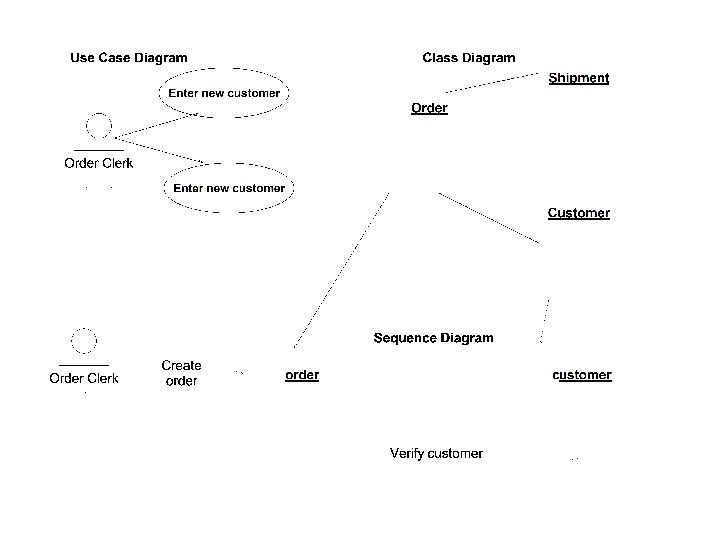
Sequence Diagram and the Use Case • Sequence diagrams are built from Use Cases. Each sequence diagram shows only the interactions pertinent to a specific use case. • Use Cases did not identify separate objects. In a Sequence Diagram, we begin to relate the objects identified in the class diagram with the Use Case. • Both the Class Diagrams and the Scenarios from the Use Case are used to build the Sequence Diagram.
The Sequence Diagram • A sequence diagram has two dimensions: – the vertical dimension represents time – the horizontal dimension represents different objects and their interactions. (although the dimensions may be reversed if desired). • Normally time proceeds down the page. • Generally, there does not have to be significance to the horizontal ordering of the objects, although logic and common sense should be applied.
Objects Lifelines Across Time
Object Interaction Arranged in a Time Sequence
Dimensions of the Sequence Diagram horizontal dimension represents different objects vertical dimension represents time
Sequence Diagram Syntax AN ACTOR AN OBJECT an. Object: a. Class A LIFELINE A FOCUS OF CONTROL A MESSAGE OBJECT DESTRUCTION a. Message() x
Objects on the Sequence Diagram • Sequence Diagrams represent a specific set of messages and interchanges between objects. • Objects are represented instead of class. • Actors can also be represented. • Objects might be depicted in 4 ways as outlined below: Unidentified or A specific object The class anonymous customer object whose identifier is Helen
Objects and Actors – The Same? • Actors and objects are different even though they often have the same name. • Actor is the external physical person who is playing a role. • Object is the computer object that maintains information about the Actor. • Obviously, we want to synchronize the internal object with the desires and actions of the external factor. • In fact, the purpose of the system is to maintain internal computer information about the ordering activities of the external person.
Messages • An OO system gets work done by a cooperative effort of individual objects that send messages to each other. • The internal events identified by the flow of events within a scenario become the messages between objects (and objects and actors). • A message is a communication between objects that conveys information with the expectation that action will ensue. The receipt of a message is a kind of event.
Description of the Sequence Diagram A sequence diagram identifies the actors and classes (or instances of classes: objects) involved in the interaction, with a timeline (called a lifeline) for each. Between the lifelines, the sequence diagram shows the messages sent between the participants in the interaction.
Symbols of the Sequence Diagram
External Actor (same as the Use Case) The external actor is graphically symbolized by a stickman figure. This illustrates a part of the environment that stimulates the system or is stimulated by it.
Object Symbol An object is graphically symbolized as a rectangular box. This illustrates an object that is created, performs actions, and might be destroyed during the lifeline.
Lifeline A lifeline is symbolized by a single broken line drawn vertically. This illustrates a representation of the existence of an object over a particular period of time.
Lifeline Node (sometimes shown, sometimes not) A lifeline node is symbolized by a small circle. This is a connection point in a lifeline.
Activation An activation is symbolized by a double broken line or a vertical rectangle. This illustrates the period during which an object is performing an action, either directly or through a subordinate procedure.
Activation as a vertical rectangle
More on the Lifeline • Lifelines show sequences. The messages higher up occur before those below. • An object role is shown as a vertical dashed line called the “lifeline. ” • The lifeline represents the existence of the object at a particular time. • If the object is created or destroyed during the period of time shown on the diagram, then its lifeline starts or stops at the appropriate point; otherwise it goes from the top to the bottom of the diagram. • An object symbol is drawn at the head of the lifeline. • Lifelines flow from TOP to BOTTOM.
Representations of the Lifeline • The lifeline represents the life of the object throughout the period of active life. • The lifeline is represented in two ways: • Vertical dashed line is used when creation and destruction is not important for the scenario. • When creation or destruction is important, a long narrow rectangle (or double dotted line) is used. • The rectangle begins when an object comes into existence and ends on destruction. • Often called the activation lifeline. The object is active during the period depicted by the rectangle.
Message Symbol A message is shown as a horizontal solid arrow from the lifeline of one object to the lifeline of another object.
Notes on Messages • In case of a message from an object to itself, the arrow may start and finish on the same object symbol. • Messages preceded with an * indicate they can be sent multiple times. • The type of arrow depicts the type of message. • The arrow is labeled with the name of the message and its argument values. • The arrow may also be labeled with a sequence number to show the sequence of the message in the overall interaction. Sequence numbers are useful on the diagrams for identifying concurrent threads of control.
Flow of Control Message (simple message) • • A flow of control message is graphically symbolized as a line with a standard directional arrowhead. This illustrates a message that passes the focus of control from one object to another. Usually asynchronous but can be used when it is not known if the message is synchronous or asynchronous Most commonly used
Synchronous Message • • A synchronous message is graphically symbolized as a line with a solid directional arrowhead. Synchronous message is one where the caller has to wait for the receiving object to complete executing the called operation before it itself can resume execution.
Asynchronous Message • • An asynchronous message is graphically symbolized as a thick line with a directional half arrowhead. An asynchronous message is one where the sender does not have to wait for the recipient to handle the message. The sender can continue executing immediately after sending the message. Common when several objects operate in parallel and in real-time systems.
Return Message • Represents explicit return of control from the object to which the message was sent
Send Message (not explored in this class) • • A send message is graphically symbolized by a "boat -shaped" object. This connects into object lifelines and acts as the source of any type of message.
Branching of Messages
Naming the Messages • Initially, messages are expressed in free format text. (Message is simply named. ) • Ultimately (and potentially only in the design model instances of the sequence diagram), the messages are rigorously specified in terms of message numbers, optional precursor conditions (termed guards), a message name and optional parameters. In this form, the message names correspond to invocations of correspondingly named operations of the recipient class.
Message Label A message symbol has 2 parts: direction arrow and the descriptor Message label descriptor The fully qualified descriptor is: [guard condition] return-value : = message-name (parameter-list) – [guard condition] is a true/false condition that is a test to see whether the message can be sent. – message-name descriptor to identify the action – (parameter-list) are the parameters to be passed – return-value is an extended message descriptor syntax is used when you want to indicate that the message is invoking a method. The extended syntax includes a possible return value from the method and the list of input variables needed by the method.
Example: message-name formats Message name only: Ring. Telephone Message name indicating parameters will be passed Item. Inquiry() Message name including parameters Create. Order. Item (Item. Id, qty) Guard condition with message name including parameters [exists. Prereqs=”true”] check. Prereqs (prereqs) Guard condition, return value and message name with parameter [First. Item] Order. Number : = Create. Order() (this can be confusing so instead of placing the return value in the message label, an additional arrow is often added on the diagram depicting the return message. )
Object Deletion • • An object deletion is graphically symbolized by an X Indicates the deletion of an object.
Sequence Diagram for a Class Registration Scenario with Prerequisites
Suggestions for Sequence Diagram Development 1. Identify all objects and actors that are involved in the scenario. Use only actors from the use case diagram and objects from classes in the class diagram. (If new actors or objects are needed, add them and then update your other diagrams. )
Step 2 2. Based on the flow of activities, identify each message that will be required to carry out the scenario. a. Identify both the source object or actor for the message and the destination object or actor. i. For the source of a message identify objects that need the service ii. Identify object that has access to the required input parameters. iii. If there is a one-to-many relationship, then frequently the object on the ‘one’ side creates the message and sends it to the object on the ‘many’ side.
Step 3 3. Next determine whether each message is always sent or whether it is sent only under certain conditions. Example: Checking for prerequisites only if course is open [Check. If. Open=“true”]exists. Pre. Reqs()
Step 4 4. Sequence the messages correctly and attach them to the appropriate lifelines of the actors and objects.
Step 5 5. Add the formal syntax to the messages (conditions, message names and passed parameters).
Step 6 6. If needed, add the response message.
Notes on Sequence Diagrams • Sequence diagrams begin interaction modeling • This is where you begin to see how the new system will ‘behave’ • More more info: http: //www. sdmagazine. com/print/documen t. ID=11072
Sequence Diagram Objectives • Sequence diagrams facilitate the discovery of things left out in the earlier static view of the system presented in the class diagram • Sequence diagrams find new classes, new attributes and many of the behaviors (operations) that are needed – In fact some suggest that methods not be assigned until now because there wasn’t enough information available
Concluding Thoughts Sequence Diagrams and Analysis • At the analysis stage you are trying to make sure that you know what the user wants. No more, no less. In effect analysis is a more detailed form of requirements capture. At this stage you are more concerned with the overall structure of interactions between the objects than you are with any minute detail of precisely how each operation works. For this reason you should choose not to take things down to too detailed a level. We're trying to capture the most important decisions about how the objects are going to interact.
Concluding Thoughts Sequence Diagrams and Analysis • At the design stage you include everything. The only reason not to include detail at the design stage is as a trade-off: we don't need to model this detail because a) it's obvious b) there's enough there for our experienced programmers to know what I mean and c) I save time not including extraneous detail. Other than that you would expect to see everything in the design sequence diagram. Detail of how each significant operation works, error values, error handling, exceptions etc, etc. • Sequence diagrams can easily become very complex - even at the analysis stage (but at the analysis stage this is usually overdone modeling). At the design stage they can become hugely complicated. We will not get to this level of detail in this course because we focus on analysis.
Top Mistakes in Creating Sequence Diagrams • Not doing a sequence diagram for each use case • Not updating class diagrams as soon as attribute and behavior discoveries are found • Turning the sequence diagram into a flow chart instead of using it to identify behaviors among objects • Not focusing on interesting methods (focusing on mundane) • Not addressing flow of control in messages
Once again the operative word is iterative.