PERMANENT MAGNET SYNCHRONOUS MOTOR DRIVES PMSM PERMANENT MAGNET


- Slides: 11

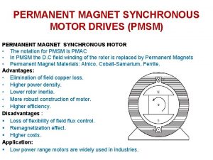
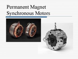
PERMANENT MAGNET SYNCHRONOUS MOTOR DRIVES (PMSM) PERMANENT MAGNET SYNCHRONOUS MOTOR • The notation for PMSM is PMAC • In PMSM the D. C field winding of the rotor is replaced by Permanent Magnets • Permanent Magnet Materials: Alnico, Cobalt-Samarium, Ferrite. Advantages: • Elimination of field copper loss. • Higher power density. • Lower rotor inertia. • More robust construction of motor. • Higher efficiency. Disadvantages : § Loss of flexibility of field flux control. § Remagnetization effect. § Higher costs. Application: § Low power range motors are widely used in industries.

Types Permanent Magnet Synchronous motors 1. Surface Mounted-PMSM § Projecting type § Inset type 2. Interioror Buried-PMSM

Types of Permanent Magnet Synchronous motors 1. Surface Mounted-PMSM § Projecting type § Inset type 2. Interioror Buried-PMSM

Types of Permanent Magnet Synchronous motors Based on nature of voltage induced in the stator classified as Sinusoid ally excited PMAC: • Stator has distributed winding. • Stator induced voltage has sinusoidal waveform. Trapezoid ally excited PMAC: • Stator has concentrated winding. • Stator induced voltage has trapezoidal waveform.

Speed control of sinusoidal PMAC • The speed of the PMAC motor is controlled by feeding them from variable frequency , voltage and current. • They are operated in self controlled mode. • In closed loop control , current regulated VSI is used. • The inverter is operated to supply motor three phase currents of the magnitude and phase commanded by reference currents isa, isb and isc which generated by a reference current generator. • The stator current templates for the three phases are generated by the rotor position sensors in such a way that δ = π/2

Speed control of sinusoidal PMAC

Sinusoidally excited PMAC

Trapezoid ally excited PMAC

Speed control of Trapezoidal PMAC • According to the torque equation torque is proportional to Id. • Regenerative braking mode operation is obtained by reversing phase currents. • This will also reverse the source current Id. • Now power flow from the machine to inverter and from inverter to dc source.

Speed control of Trapezoidal PMAC

Trapezoidally excited PMAC
 Pmac drives
 Pony motor starting synchronous motor
 Three phase synchronous generator
 Pony motor starting synchronous motor
 Difference between permanent magnet and temporary magnet
 Difference between permanent magnet and temporary magnet
 Blpm dc motor
 Ersatzschaltbild pmsm
 Relucatnce
 Slip speed of induction motor
 Torque equation of synchronous motor
 Coupled circuit
