Designing of Synchronous State Machine Synchronous all of


 Design using T flip-")
 Design")


- Slides: 10
Designing of Synchronous State Machine Synchronous: all of the flip flops use the same clock signal Example 1: Suppose a circuit is required to recognize the 3 -bit pattern (101), and output (z=1) whenever it occurs in the continues serial input (X) to the circuit. then the circuit will reset and start testing again. Solution: Mealy state diagram Moore state diagram 37 State tables: Present state A B C D N. s X=0 A C A A N. S X=1 B B D B Output X=0 0 0 Output X=1 0 0 1 0
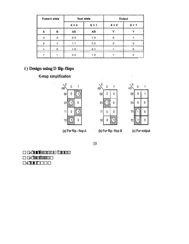
Mealy State table Present state A B C D N. s X=0 A C A A N. S X=1 B B D B Output Z 0 0 0 1 Moore State table Example 2: A sequential circuit has one input and one output. The state diagram is shown in Figure (5). Design the sequential circuit with a) D flip-flops b) T flipflops c) RS flip-flops and d) JK flip-flops. 38 Fig. 5: State diagram
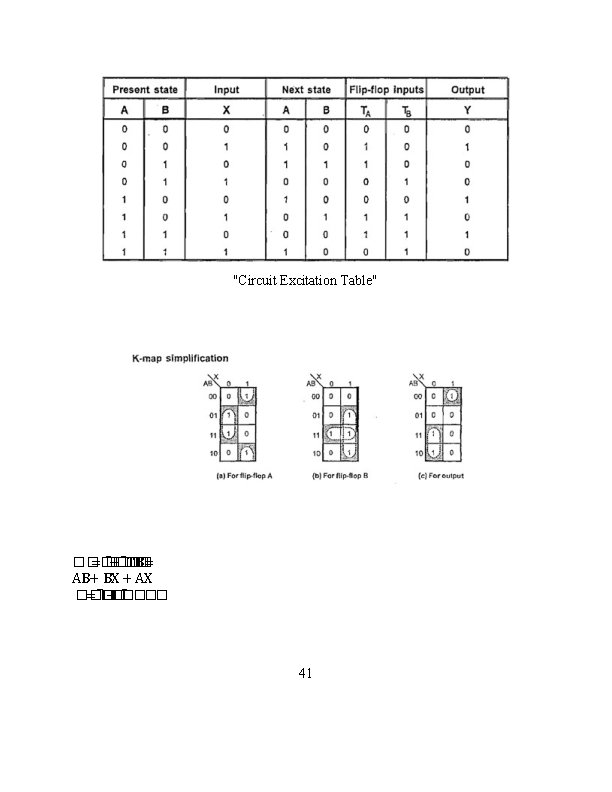
"Logic diagram of given sequential circuit using D flip-flop" ii) Design using T flip- flops : "Excitation table for T flip-flop" 40
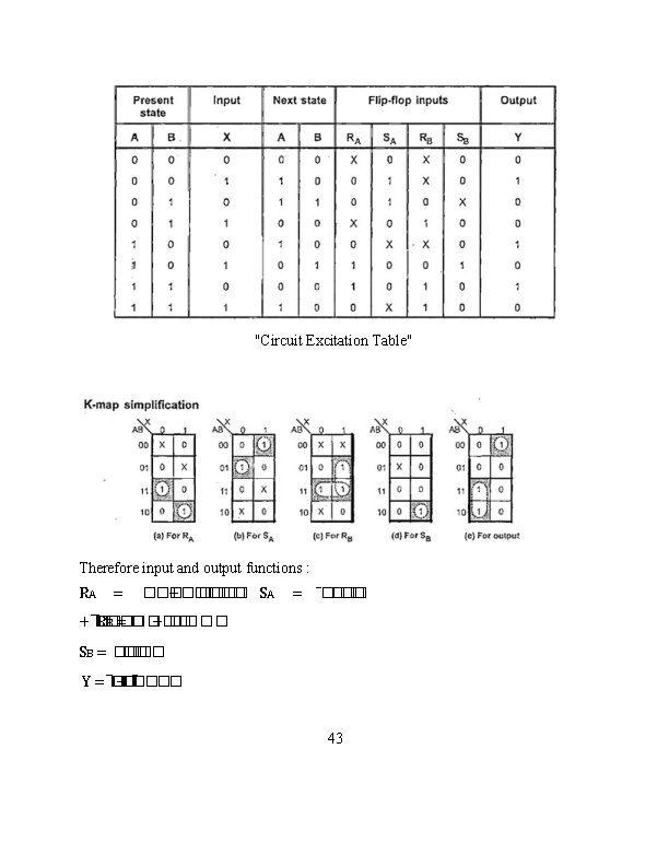
"a & b Logic diagram of given sequential circuit using T flip-flop" iii) Design using RS flip-flops: "Excitation table for RS flip-flop" 42
"Logic diagram of given sequential circuit using RS flip-flop" iv. Design using JK Flip-Flops: "Excitation table for JK flip-flop" 44
"Circuit Excitation Table" Therefore, input and output functions: � � JA = ���� + JB� � = � � KA = ���� + K� � A= AX A+X � Y=� +� ����� 45
"Logic diagram of given sequential circuit using JK flip-flop"