12 2 Asynchronous or Ripple Counters Asynchronous counter


- Slides: 28
12 -2 Asynchronous or Ripple Counters Asynchronous counter is made up of a set of J-K flip -flop connected in toggle-mode as shown 3 -bit asynchronous down counter
3 -bit Asynchronous counter o o The counter has three outputs Q 2, Q 1, Q 0 The counter is a 3 -bit counter with 8 possible states. o Clock is applied only to FF 0. Output of FF 0 is Clock of FF 1 and so forth. o This is an asynchronous counter because all flip-flops will not change states at the same time (not in synchronism with the clock) Asynchronous counters are also called RIPPLE COUNTER since clock appears to ripple through each flip-flop connected in series The timing diagram is the best way to analyze ripple counters o o
Timing diagram 3 -bit asynchronous down counter
3 -bit synchronous down counter The timing diagram shows the output states for each transition of the clock pulse n The counter is a binary counter (000, 111, 110, 101, 100, 011, 010, 001, 000, 111, …… ) n The counter is a down counter (counts from 7 to 0) n The counter will function continuously (it recycles) n Frequency division – each FF have an output frequency of ½ the input. The output frequency of the last FF is the clock frequency divided by the MOD of the counter.
Timing diagram to truth table Q 2 Q 1 Q 0 1 1 1 0 0 0 1 1 0 0 0 1 1 1
Truth table to State diagram
4 -bit asynchronous down counter The ripple counter can be extended to include more states by simply adding more flip-flops in series. n The MOD number is 16 n The counter will have 16 states (0000, 1111, 1110, 1101, 1100, 1011, 1010, ……… 0000)
3 -bit asynchronous up counter A 3 -bit ripple counter can be constructed by changing positive edge-triggered to negative edge-triggered flip-flops.
3 -bit asynchronous up counter
3 -bit synchronous ? ? counter using positive-edge triggered flip-flops In this figure we have changed the flip-flop back to positive-edge triggered flip-flop, but we have inverted the clock pulses entering F 1 and F 2 by using the Qˈoutputs.
3 -bit synchronous up counter using positive-edge triggered flip-flops
Up/down Counter q q We can combine the up counter and down counter circuits into an up/down counter. The counter has a control input S that selects the desired sequence.
Up/down Counter q The control input S selects the count sequence: q If S = 0 - counts up q If S = 1 - counts down
MUltiple. Xer output Select Line S S = 1 Output = A S = 0 Output = B
Up counter Down counter
Example: Analyze the 4 -bit ripple counter by drawing a timing diagram
Counters with MOD Number <2 N o o o A counter does not necessarily have to cycle through all possible states. Example: Design a asynchronous counter that counts from 0 to 5 To implement the above counter, we need a 3 -bit counter. A 3 -bitcounter cycles through 8 states (0 through 7) Modify the 3 -bit counter to automatically reset to 000 after the count reaches 101 (5)
Counter Decoding
Counter Decoding o o o We monitor the output of the counter using Nand gate (count decoder) The output of the Nand gate is tied to the direct Clear (asynchronous) input of the F-F When the count reaches 110 (6), the Nand gate produces a low output that immediately resets the counter.
Timing diagram of 0 -5 counter Notice the glitch produced on the Q 1 waveform when the count reaches 6. This represents the brief time required to reset the counter
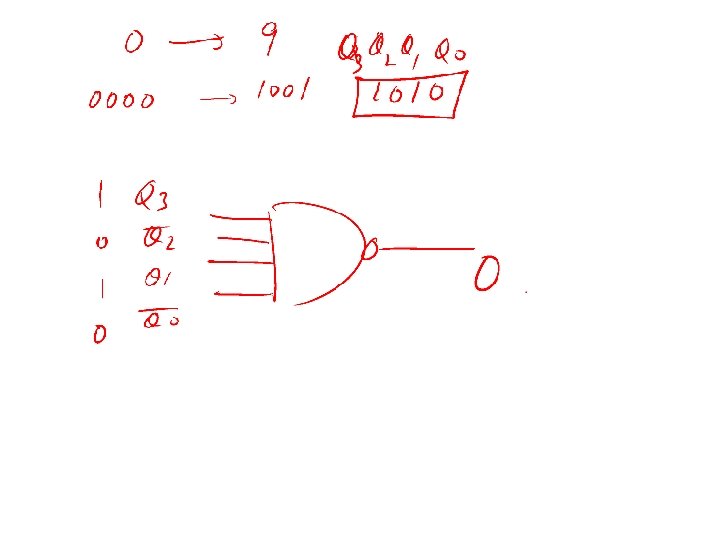
BCD Ripple Counter o o A BCD counter cycles through ten states (0 through 9) We need a 4 -bit counter to count up to 1001. A BCD counter is implemented with a modulus of ten (uses only 10 of possible 16 states) BCD counter is also called a DECADE counter.
BCD Counter Design o o o o First construct a 4 -bit binary counter (up or down) Modify the circuit to automatically reset to 0000 after the count reaches 1001 (9) Note the J inputs of all the flip-flops are connected together to the output of the Nand gate. The output of the Nand gate will be 1 for all counts from 0000 to 1000 Since the J and K inputs to all flip-flops is “ 1”, the F-F are in the toggle mode during states 0 through 8. When the counter reaches 1001, the output of the Nand gate is “ 0”. Since J =0 and K= 1, on the next clock transition all the F-F resets and the counter resets to 0000.
Asynchronous BCD up counter
Timing diagram for BCD counter
Homework: Design a asynchronous counter that counts from 3 to 7 Solution:
Asynchronous counter to count from 0 to 20 How many flip-flop do we need? Count to decode for resetting the counter = Logic Circuits:
Propagation Delay in Ripple Counters o o Ripple counters are simple, but the cumulative propagation delay can cause problems at high frequencies. For properation the following apply: Tclock N x tpd Fmax=1/(N x tpd) Where N = number of FFs tpd = propagation delay time Fmax= maximum frequency