EEE 326 SYNCHRONOUS MACHINE MODULE OUTLINE FOR SYNCHRONOUS


 • Generators • Most important application of sm is that")


 : characteristics • Small diameter • Long enough")


 E 3")


 • Some(small/medium type) synchronous generators as")
 Fig. 6: Machine Connected to grid")


")
")

 the rotor is")
 - SIMPLIFIED •")


")
")


")

 Synchronous • the rotation of the")


- Slides: 110
EEE 326 SYNCHRONOUS MACHINE MODULE
OUTLINE FOR SYNCHRONOUS MACHINES • • • Types Construction Synchronous reactance Equivalent circuits Regulation Steady state operation Special generators Synchronous motor Power factor control and starter Independent generators Parallel operation of synchronous generators.
Key Learning outcomes • Equivalent circuits for motors and generators • Power factor correction using synchronous motors • Parallel operation of synchronous generators
What are synchronous machines? What types exist? • Electrical machines with a rotor rotating at a speed directly related to the frequency of the current in its stator Types include: • motors • generators
What’s the relationship between, speed, frequency and number of poles? •
TYPES of synchronous machines(sm) • Generators • Most important application of sm is that of a generator(usually 3 phase); also called Alternator • They are the main source of electrical energy • They handle enormous power • They are energy converters • Largest units are those driven by Gas, steam and water power • Motors are used for power factor correction
CONSTRUCTION – General Information • Essentially the same for motors and generators • They can be used interchangeably albeit that generator are produced to handle larger powers than motors as required by large electrical networks • Also depends on the prime mover(hydropower, steam or gas) • For hydropower operation, a large number of poles are necessary due to slow speed of the rotor; hence the diameters of hydro turbines are large. • For steam or gas operation, the rotor speeds are high and the rotor diameters are small; this limits the magnitude of the forces in the rotor
CONSTRUCTION – Stator • Similar to that of the squirrel case induction motor • To convert a squirrel case induction motor to a synchronous generator, essentially we change the rotor, ie, replace the rotor of the squirrel case induction motor • The rotor is wound as an electromagnet to carry dc current drawn from an external supply(rather than carrying an ac current) • For small machines a permanent magnet can also be used • Some small machines have stationary field poles and a rotating armature(the part carrying the ac supply current or load current in case of an ac generator) • For large machines(designed to deliver many thousands of volts), the armature is stationary due to difficulties that would arise in insulating the rotor
CONSTRUCTION – Stator •
Construction - Rotor • From equation 1, the rotor speed is determined by the number of poles and frequency • The highest operating speed for a synchronous motor is obtained when the number of poles is 2 , implying 1 pole pair • For a frequency of 50/60 Hz, the speed would be 3000/3600 rpm • For variable frequency sources, speeds of 10, 000 rpm could be contemplated(example: auxiliary power for aircrafts) • With high speeds; large centripetal forces are produce; these work against the large diameters and protruding pole parts; • Cylindrical Rotors(smooth slotted rotors) are used for steam/gas driven generators which spin at 3000 rpm/3600 rpm for 50/60 hz and a pole pair(Small diameter rotors)
Construction - Cylindrical Rotors(smooth slotted rotors) : characteristics • Small diameter • Long enough to establish the volume required for a given power output • For generators driven by a water turbine, more poles are required due to the reduced speed • This results in a larger rotor diameter(say 10 m) • The rotor poles protrude, the windings are concentrated and the airgaps are non uniform
EXCITATION • Generation of electricity is based on Faraday’s law: • an emf is induced when a time varying field links a conductor • For induction to occur, the magnetic lines of force on the rotor must cut the stator conductors • The lines of force could come from a permanent magnet but for large generators, the rotor field is formed by external injection of current into the pole windings. • Since the rotor is moving with the stator, slip rings and brushes are required • In brushless excitation, (the main field is provided through rotating rectifiers, supplied through induction from another smaller exciter or permanent magnet) neither slip rings nor brushes are use; this allows for less maintenance • WHY DO BRUSHLESS ALTERNATORS UNDERGO LESS MAINTENANCE?
THEORY OF OPERATION FIG. 1 : ELEMENTARY SYNCHRONOUS GENERATOR
THEORY OF OPERATION •
THEORY OF OPERATION •
THEORY OF OPERATION –EMF EQUATIONS •
RELATIONSHIP BETWEEN THE STATOR INDUCED EMF AND THE ROTOR FIELD CUNRENT – the open circuit characteristics GENERATOR OCC
GENERATOR OCC •
PITCH FACTOR AND QUALITY OF THE GENERATED EMF •
Short pitching • Short pitching improves winding waveform • If one slot is shorted in a pole pitch of six(83. 3%), the 5 th harmonic is removed completely; the 7 th harmonic is reduced to 59%. • For star connected stator, the triplen harmonics do not appear at all • Figure 3 shows a diagrammatic representation of short pitching
Short pitching in Diagram
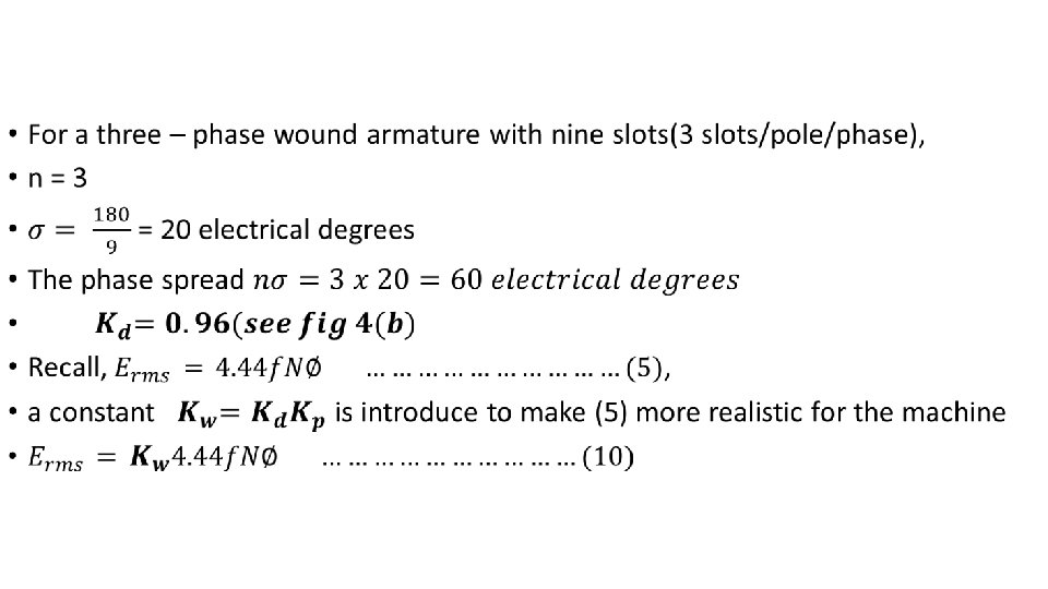
How do we further improve the voltage waveform • Coils in the stator are connected together to form a phase band(see fig 4(a) with two adjacent coils distanced by one slot pitch • Because of this phase shift, the phasor sum and the arithmetic sum of the induced voltage are not the same, the latter being higher than the former(see Fig 4(b)
E T LO S T 2 SLOT 1 E (b) E 3
Breadth factor defined •
SYNCHRONOUS MACHINE EQUIVALENT CIRCUIT – Modelled Equivalent Circuit •
Generator Model – Equivalent circuit •
Generator Model – Equivalent circuit •
Modelled Equivalent Circuit - Ef Fig. 5: Synchronous machine Model
SIMPLIFIED MODEL – class work • Ignore armature resistance • Write the modified version of equation 13 • What does the reactance represent • Sketch the modified model • Sketch the phasor diagram of the actual and modified model
WORKED EXAMPLE 1 • SOLUTION
SOLUTION TO EXAMPLE 1 f EQUIVALENT CIRCUIT PHASOR DIAGRAM
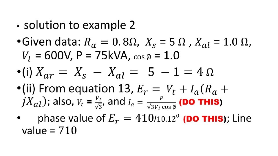
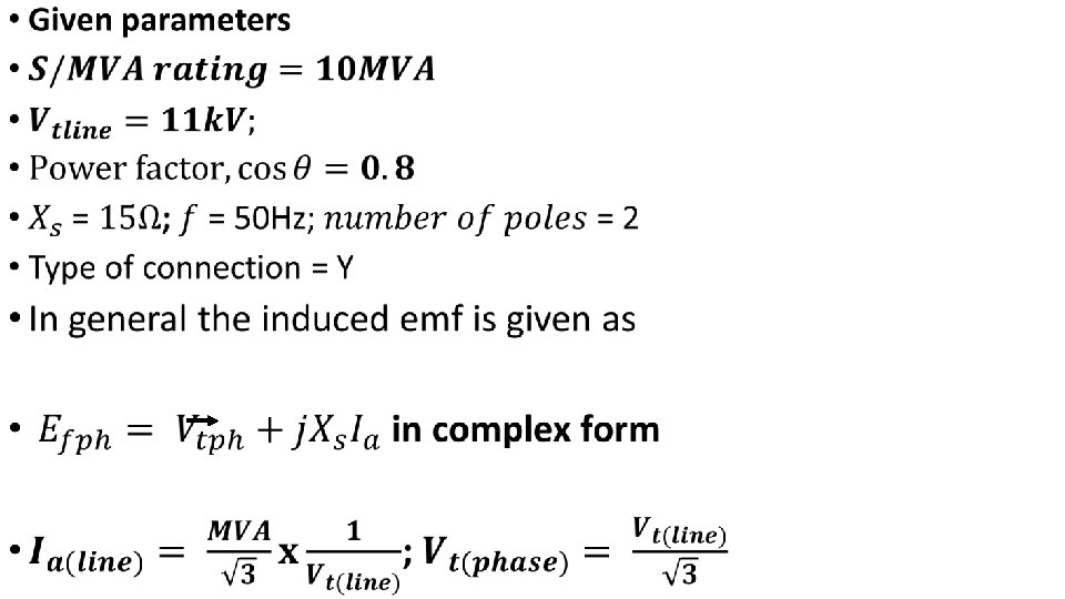
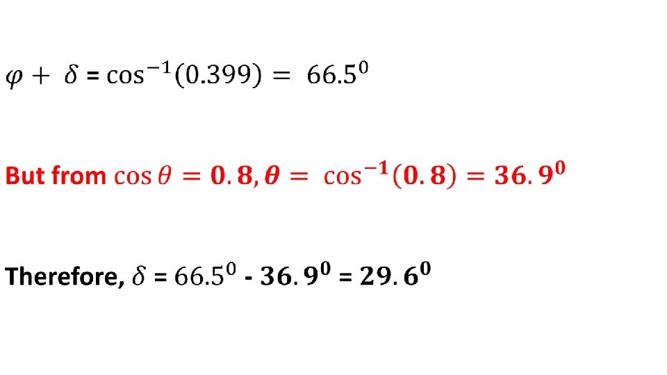
WORKED EXAMPLE 2 •
ILLUSTRATION OF THE EFFECT OF POWER FACTOR ON ARMATURE REACTION Unity pf Distorts the main flux Zero pf lagging(pure inductive load) Zero pf leading(pure capacitive load) General pf lagging(80% of industrial loads are of the R – L) type Demagnetisi Magnetising Distorts & ng effect; effect, Demagnetise output Output s; effect of voltage reduced increased output General pf leading(R – C) Distorts & Magnetises; effect of increased output
SYNCHRONOUS MACHINES CONNECTED TO THE GRID(INFINITE BUS BAR) • Some(small/medium type) synchronous generators as earlier considered are suitable for ISOLATED mode of use • Examples include remote farming communities; stand – by plant for special/sensitive facilities where power security is essential(e. g. computer/Data centers, hospitals[ICUs, theaters, radiographic units, MIRs etc]); manufacturing industries, process plants etc • Largest type SMs are connected as part of a large network of generators – Electricity Grid • This Grid is considered to have: • (i) Constant Voltage • (ii) Zero phase angle • This is shown in Fig. 6(Machine connected to grid)
SYNCHRONOUS MACHINES CONNECTED TO THE GRID(INFINITE BUS BAR) Fig. 6: Machine Connected to grid
DETERMINATION OF THE POWER DELIVERED TO THE BUS BAR •
DETERMINATION OF THE POWER DELIVERED TO THE BUS BAR – CONT’D •
DETERMINATION OF THE POWER DELIVERED TO THE BUS BAR – CONT’D •
DETERMINATION OF THE POWER DELIVERED TO THE BUS BAR – CONT’D •
DETERMINATION OF THE POWER DELIVERED TO THE BUS BAR – CONT’D •
DETERMINATION OF THE POWER DELIVERED TO THE BUS BAR – CONT’D •
TUTORIAL EXAMPLE 1/SOLUTION •
SOLUTION TO TUTORIAL 1 – cont’d
SOLUTION TO TUTORIAL 1 – cont’d
SIMPLIFIED MODEL OF A SYNCHRONOUS GENERATOR – How does this simplification affect the phasor diagram? • Fig. 7 : Simplified model of synchronous generator
TUTORIAL EXAMPLE 2/SOLUTION • Draw the phasor diagrams of a synchronous generator under the following conditions: • (i) lagging power factor • (ii) leading power factor • (iii) maximum power • LAGGING POWER FACTOR PHASOR
TUTORIAL EXAMPLE 2/SOLUTION – CONT’D • Fig. 8(ii)
Fig. 8(iii)
THE SYNCHRONOUS MOTOR • It is not self starting • The rotor oscillates; the rotor pole is attracted, then repulsed as the rotating field sweep past it • This vibration(pole slipping) is unacceptable for its severity • There are two possible ways to solve this problem:
There are two possible ways to solve this problem: • (i) the rotor is equipped with a squirrel cage winding(damper winding). This enables the rotor to accelerate towards synchronous speed and when close enough, the rotor will ‘lock on’ to the field • (ii) the rotor is driven externally to synchronous speed and when the rotor has locked on, the driving unit is disengaged
SYNCHRONOUS MOTOR MODEL(EQUIVALENT CIRCUIT) - SIMPLIFIED •
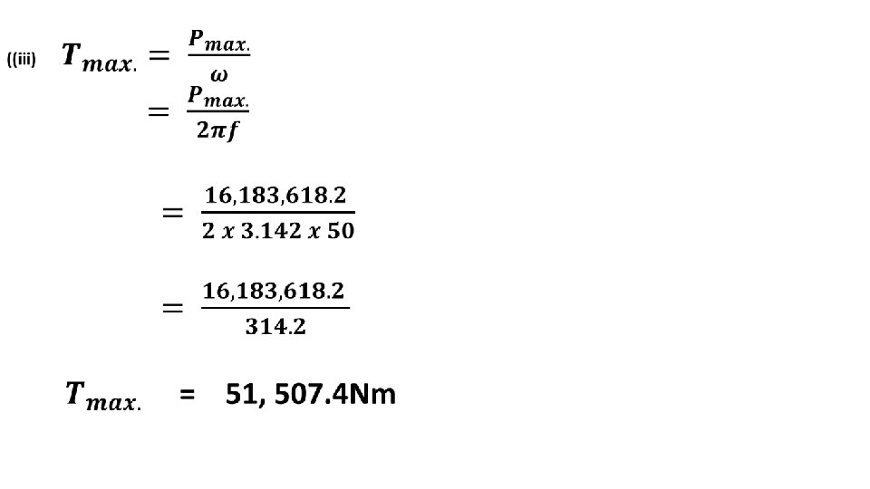
MOTOR POWER AND OTHER EQUATIONS •
TUTORIAL EXAMPLE 4 - QUESTION •
SOLUTION •
SOLUTION TO TUTORIAL 4 CONT’D TASK 1 : EXCITATION VOLTAGE •
TASK 1 : EXCITATION VOLTAGE – cont’d •
TASK 2 – LOAD ANGLE •
TUTORIAL EXAMPLE 5 •
SOLUTION •
SOLUTION •
TUTORIAL EXAMPLE 5 • POWER FACTOR
TUTORIAL EXAMPLE 5 - PHASOR DIAGRAM •
USING SYNCHRONOUS MOTORS FOR POWER FACTOR CORRECTION •
USING SYNCHRONOUS MOTORS FOR POWER FACTOR CORRECTION – cont’d • The motor is thus used as a synchronous condenser for the purpose of power factor correction • In this mode, the motor is run on load and the excitation is adjusted to achieve the level of correction required • Quick trial: Draw the phasor diagrams for leading, lagging and unity pf
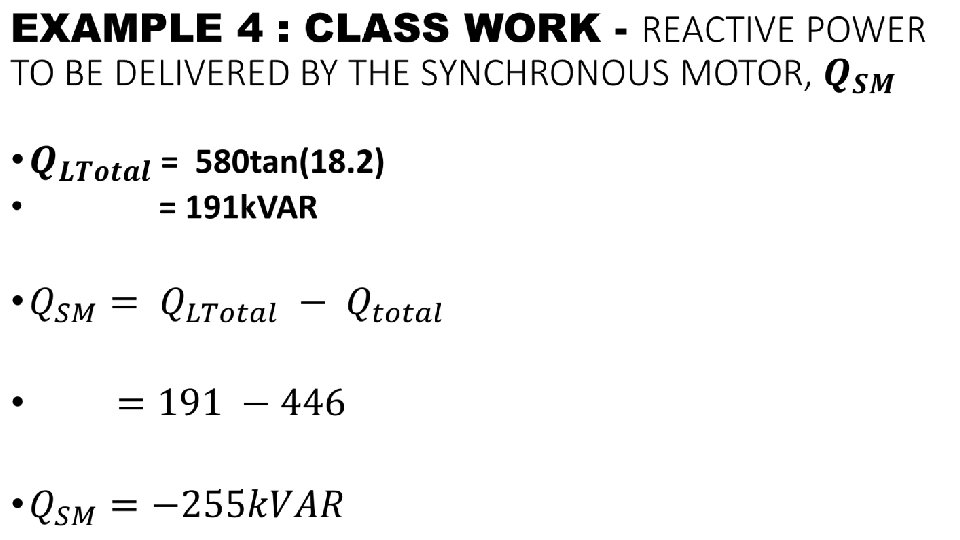
EXAMPLE 4 : CLASS WORK - QUESTION • The most important loads of a production facility are Unit 1 powered by 250 k. W, 0. 6 power factor lagging induction motor and Unit 2, powered by a 150 k. W, 0. 8 power factor lagging motor. These motors are connected in the same lines. It is required to increase the power factor to 0. 95 by installing a synchronous motor in parallel with the motors; the synchronous motor drawing 180 k. W. Calculate the reactive power to be supplied by the motor and its rating in k. VA
SOLUTION •
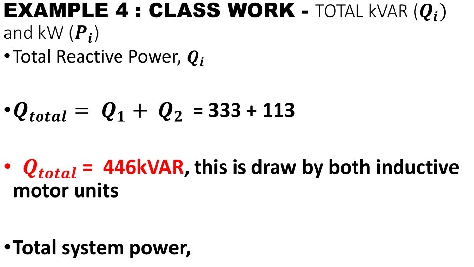
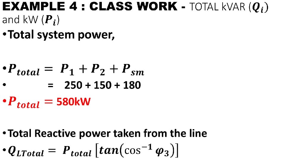
• POWER DRAWN BY RESPECTIVE UNITS (�� _�� & �� _�� )
• POWER DRAWN BY RESPECTIVE UNITS (�� _�� & �� _�� )
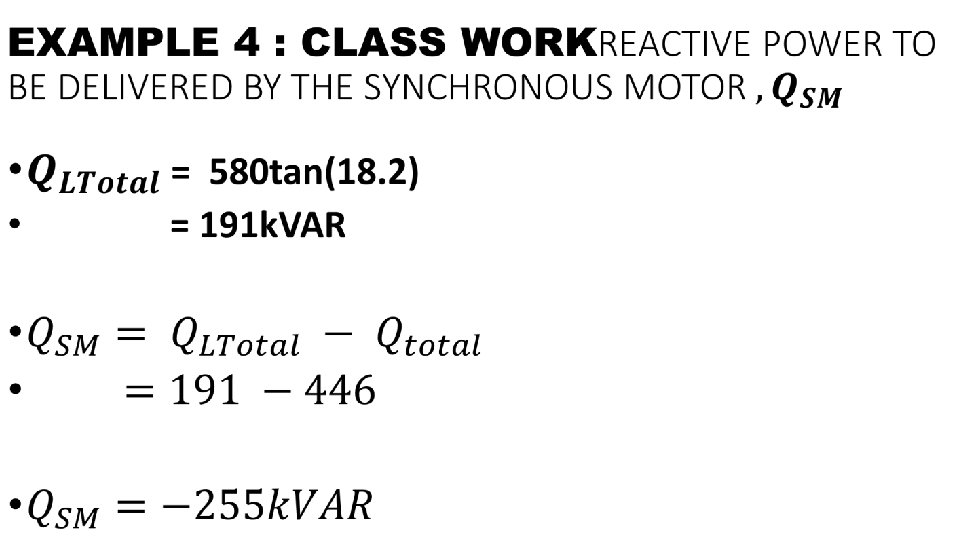
EXAMPLE 4 : CLASS WORK - SYNCHRONOUS MACHINE RATING IN k. VA •
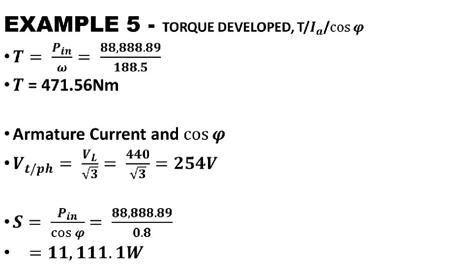
EXAMPLE 5 • QUESTION
EXAMPLE 5 - SOLUTION •
EXAMPLE 5 - EXCITATION VOLTAGE AND POWER ANGLE •
EXAMPLE 5 - EXCITATION VOLTAGE AND POWER ANGLE •
Summary for Power Factor Correction Using a Synchronous Motor • A Synchronous Machine when used for the purpose of reactive power control is called a Synchronous Compensator/Condenser/Capacitor. • It is a Synchronous Motor, whose shaft spins freely without any torque on it except its weight. • A Synchronous Machine when used for power factor correction has two circuits; • a Stator Circuit which is connected to the grid and • a Rotor Circuit which is called Field winding/Excitation Winding.
Summary for Power Factor Correction Using a Synchronous Motor – cont’d • The field winding is controlled by a solid state voltage and frequency regulator. • Increasing the device's field winding excitation results in its furnishing reactive power (VARs) to the system and • decreasing the field winding excitation causes absorption of reactive power from the system (VARs).
SYNCHRONOUS MACHINES V - CURVES P. F. ITY Y UN LIT I B A ST MIT LI 400 ARMATURE CURRENT(A) 300 LO AD 200 NO • V – curves of a synchronous machines are plots of field current against armature current at various levels of loading. • They apply only to synchronous motors. • There is always a level of excitation, corresponding to unity power factor at which the armature current is minimum • Fig. V shows the V – curves for a synchronous motor • Note: a stability limit exist beyond which stability cannot be maintained during operations; Excitation below this limit causes the motor to pull out of synchronism V - CURVES 100 LAGGING P. F 0 50 LEADING P. F 100 EXCITATION(V) 150
TYPICAL SYNCHRONOUS MACHINES V - CURVES
TYPICAL SYNCHRONOUS MACHINES V - CURVES • ADVANTAGES OF A SYNCHRONOUS CONDENSER • A synchronous condenser provides step-less automatic power factor correction with the ability to produce up to 150% additional vars. • The system produces no switching transients and is not affected by system electrical harmonics (some harmonics can even be absorbed by synchronous condensers). • They will not produce excessive voltage levels and are not susceptible to electrical resonances. • Because of the rotating inertia of the synchronous condenser, it can provide real time voltage support during system short circuits.
ASSIGNMENTS •
PARALLEL OPERATION OF GENERATORS • An alternator is an ac generator • In an alternator, an e. m. f is induced in the stator(stationary wire) with the influence of a rotating magnetic field(rotor) due to Faraday’s law of induction. • Due to the synchronous speed of rotation of field poles, it is also known as a synchronous generator • For the parallel operation of an alternator, the efficiency of interconnected ac systems is the focus.
PARALLEL OPERATION OF GENERATORS • In this case, there shall be more than two alternators connected in parallel in generating stations • There are necessary and sufficient conditions for generators to be connected and operated in parallel • There is also the terms/terminologies need to define some
DEFINITION OF TERMS Synchronisin g/Synchronisa tion: The process of connecting two alternators or an alternator and an infinite bus bar system in parallel. 2 PARALLEL CONNECTED GENERATORS
DEFINITION OF TERMS 2 PARALLEL CONNECTED GENERATORS The Running machine is the machine which carries the load.
DEFINITION OF TERMS 2 PARALLEL CONNECTED GENERATORS The. Incoming machine is the alternator or machine which has to be connected in parallel with the system.
Condition for Parallel Operation of Alternator 4 CONDITIONS • The phase sequence of the incoming machine voltage and the bus bar voltage should be identical; • The R. M. S line voltage (terminal voltage) of the bus bar or already running machine and the incoming machine should be the same; • The phase angle of the two systems should be equal; and • The frequency of the two terminal voltages (incoming machine and the bus bar) should be nearly the same. FURTHER PHASOR/LINE EXPLANATIONS This three-phase supply consists of three phases, generally represented as R, Y and B or A, B and C Yellow OR B CCW OR +VE Red OR A Blue OR C
Condition for Parallel Operation of Alternator CONDITIONS - 1 FURTHER PHASOR/LINE EXPLANATIONS • The phase This three-phase supply consists of three phases, sequence of generally represented as R, Y and B or A, B and C the incoming Yellow OR B machine CCW OR +VE voltage and the bus bar Red OR A voltage should be Blue OR C identical;
Condition for Parallel Operation of Alternator CONDITION 2 • The R. M. S line voltage (terminal voltage) of the bus bar or already running machine and the incoming machine should be the same; FURTHER PHASOR/LINE EXPLANATIONS This three-phase supply consists of three phases, generally represented as R, Y and B or A, B and C Yellow OR B CCW OR +VE Red OR A Blue OR C
Condition for Parallel Operation of Alternator CONDITION 3 FURTHER PHASOR/LINE EXPLANATIONS This three-phase supply consists of three phases, • The generally represented as R, Y and B or A, B and phase Yellow OR B C angle of CCW OR +VE the two Red OR A systems should be equal; Blue OR C and
Condition for Parallel Operation of Alternator CONDITION - 4 • The frequency of the two terminal voltages (incoming machine and the bus bar) should be nearly the same. FURTHER PHASOR/LINE EXPLANATIONS This three-phase supply consists of three phases, generally represented as R, Y and B or A, B and C Yellow OR B CCW OR +VE Red OR A Blue OR C
WHY WE MUST STRICTLY ADHERE TO ALL THE 4 CONDITIONS • Large power transients will occur when frequencies are not nearly equal. • Departure from the above conditions will result in the formation of power surges and current. • It also results in unwanted electro-mechanical oscillation of rotor which leads to the damage of equipment.
General Procedure for Paralleling Alternators Intro to procedure • The figure shows an alternator (generator 2) being paralleled with a running power system (generator 1). • These two machines are about to synchronize for supplying power to a load. • Generator 2 is about to parallel with the help of a switch, S 1. • This switch should never be closed without satisfying the above conditions Connection diagram
General Procedure for Paralleling Alternators – 2 methods to check phase sequence cont’d Procedure • They are as follows First one is using a Synchroscope. It is not actually check the phase sequence but it is used to measure the difference in phase angles. • To make the terminal voltages equal. This can be done by adjusting the terminal voltage of • incoming machine by changing the field current and make it equal to the line voltage of running system using voltmeters. • There are two methods to check the phase sequence of the machines. Second method is three lamp method (Figure 2). Here we can see three light bulbs are connected to the terminals of the switch, S 1. Bulbs become bright if the phase difference is large. Bulbs become dim if the phase difference is small. The bulbs will show dim and bright all together if phase sequence is the same. The bulbs will get bright in progression if the phase sequence is opposite. This phase sequence can be made equal by swapping the connections on any two phases on one of the generators
General Procedure for Paralleling Alternators – cont’d • Next, we have to check and verify the incoming and running system frequency. It should be nearly the same. This can be done by inspecting the frequency of dimming and brightening of lamps. • When the frequencies are nearly equal, the two voltages (incoming alternator and running system) will alter the phase gradually. These changes can be observed and the switch, S 1 can be made closed when the phase angles are equal.
Advantages of Parallel Operating Alternators Ø Ø When there is maintenance or an inspection, one machine can be taken out from service and the other alternators can keep up for the continuity of supply. Load supply can be increased. During light loads, more than one alternator can be shut down while the other will operate in nearly full load. High efficiency. Ø Ø Ø The operating cost is reduced. Ensures the protection of supply and enables costeffective generation. The generation cost is reduced. Breaking down of a generator does not cause any interruption in the supply. Reliability of the whole power system increases.
MOTORS AND THEIR USES – COST VS APPLICATION VS TECHNOLOGY(AC/DC)
AC MOTORS • AC motors are highly flexible in many features including speed control (VSD Variable Speed Drives) • they have a much larger installed base compared to DC motors, • The current trend for VSD is to add more features and programmable logic control (PLC) functionality, • these are advantages for the experienced used, but require greater technical expertise during maintenance. • some of the key advantages are: Low power demand on start Controlled acceleration Adjustable operational speed Controlled starting current Adjustable torque limit Reduced power line disturbances
TYPES OF AC MOTORS AND APPLICATIONS Induction (Asynchronous) Synchronous • the rotation of the rotor is synchronized with the frequency of the supply current ; • the speed remains constant under varying loads; • It is ideal for driving equipment at a constant speed; and • They are used in high precision positioning devices like robots, instrumentation, machines and process control • uses electromagnetic induction from the magnetic field of the stator winding to produce an electric current in the rotor and hence Torque; • These are the most common type of AC motor and important in industry due to their load capacity with Single. Phase induction motors being used mainly for smaller loads, like used in house hold appliances whereas • Three-Phase induction motors are used more in industrial applications including like compressors, pumps, conveyor systems and lifting gear.
GENERATOR TYPES AND APPLICATIONS POWER STATION & TRAILER MOUNTED • In grid system for public supply networks, a number of high power generator sets may operate in parallel from different power station; • Some portable supplies, often trailer-mounted, where alternative supply system is not available. PRIVATE/INDEPENDENT/standby • Sometimes private or independent generators may run in parallel with the public supply system or isolated from it when demand is less e. g peak shaving to reduce the maximum demand for electricity consumed by a user and this can avoid large financial penalties during times of normally high demand on the grid system; Keep standby or emergency generators to protect the supply to the critical circuits such as hospitals, fire service, and water supply system; Some time is required some temporary supply system by the construction industry or in cases of any breakdown.
GENERATOR TYPES AND APPLICATIONS Solar generator 1. -Solar powered generators are great replacement for traditional gas powered models. These are perfect for indoor use. They are also capable supplying direct current. So theses are perfect for camping, RV's and specifically designed low voltage appliances for a residence. These generators designed to supply electrical power for compatible electrical. Residential stand by generator • -These generators are very efficient. Portable generators can provide critical backup power in an emergency situation. These generator generic pressure washers give you the power to clean everything around the house.
GENERATOR TYPES AND APPLICATIONS Commercial stand by generator Industrial generator-They • It is a worldwide power generator system. It has switchgear, automatic transfer switches and paralleling equipment. These are used in a very large scale. These are quite same as residential generators and starts at 30, 000 watts • They achieve efficiency levels of up to 99 percent. These industrial generators are available in different types like natural gas, diesel, and many more. For the industrial companies, the installation of industrial generator is very essential.