THREE PHASE INDUCTION MOTOR Introduction 3 phase induction


 It has simple and rugged construction. (ii) It is relatively cheap. (iii)")
 It is essentially a constant speed motor and its speed cannot be")


 Φ 1 =")
 Φ 1 =")
 Φ 1 =")
 Φ 1 = ΦM")


 When 3 -phase stator winding is energized from a 3 -phase supply,")
 The current-carrying rotor conductors are placed in the magnetic field produced by")


 The quantity Ns N is sometimes")


, i. e. s =1, the")


")


 Stator inpur, Pi = Stator output +Stator losses (Iron loss + Cu loss)")


- Slides: 94
THREE PHASE INDUCTION MOTOR
Introduction 3 -phase induction motors are the most common & frequently encountered machines in industry - simple design, rugged, low-price, easy maintenance - wide range of power ratings: fractional horsepower to 10 MW - run as constant speed from no-load to full load - speed depends on the frequency of the power source • not easy to have variable speed control • requires a variable-frequency power-electronic drive for optimal speed control
Advantages (i) It has simple and rugged construction. (ii) It is relatively cheap. (iii) It requires little maintenance. (iv) It has high efficiency and reasonably good power factor. (v) It has self starting torque.
Disadvantages (i) It is essentially a constant speed motor and its speed cannot be changed easily. (ii) Its starting torque is inferior to d. c. shunt motor.
Construction
Construction An IM has two main parts - a stationary stator • • consisting of a steel frame that supports a hollow, cylindrical core, constructed from stacked laminations, having number of evenly spaced slots, providing space for stator winding Stator of IM
Construction - a revolving rotor • composed of punched laminations, stacked to create a series of rotor slots, providing space for the rotor winding one of two types of rotor windings • conventional 3 -phase windings made of insulated wire (wound-rotor) » similar to the winding on the stator • aluminum bus bars shorted together at the ends by two aluminum rings, forming a squirrel-cage shaped circuit (squirrel-cage)
Squirrel-cage squirrel-cage: conducting bars laid into slots and shorted at both ends by shorting rings.
wound-rotor Wound-rotor: complete set of three-phase windings exactly as the stator. Usually Y-connected, the ends of the three rotor wires are connected to 3 slip rings on the rotor shaft. In this way, the rotor circuit is accessible.
Construction Squirrel cage rotor Wound rotor Notice the slip rings
Construction Slip rings Cutaway in a typical woundrotor IM. Notice the brushes and the slip rings Brushes
Rotating Magnetic Field Balanced three phase windings, i. e. displaced 120 degrees form each other, fed by balanced three phase source A rotating magnetic field with constant magnitude is produced, rotating with a speed Where fe is the supply frequency and P is the no. of poles and nsync is called the synchronous speed in rpm
Rotating Magnetic Field
Rotating Magnetic Field
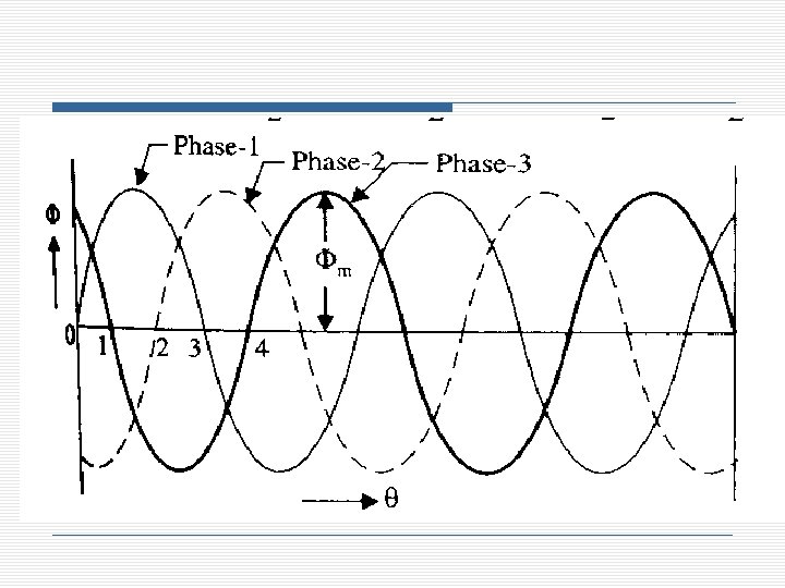
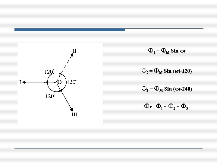
When ωt = 0 i. e. at point o (fig. 1) Φ 1 = ΦM Sin ωt = 0 Φ 2 = ΦM Sin (ωt-120) = -√ 3/2 ΦM Φ 3 = ΦM Sin (ωt-240) = √ 3/2 ΦM Φr = Φ 1 + Φ 2 + Φ 3 = 2 x √ 3/2 ΦM Cos 30 = 3/2 ΦM
When ωt = 60 i. e. at point 1 (fig. 1) Φ 1 = ΦM Sin ωt = √ 3/2 ΦM Φ 2 = ΦM Sin (ωt-120) = - √ 3/2 ΦM Φ 3 = ΦM Sin (ωt-240) = 0 Φr = Φ 1 + Φ 2 + Φ 3 = 2 x √ 3/2 ΦM Cos 30 = 3/2 ΦM
When ωt = 120 i. e. at point 2 (fig. 1) Φ 1 = ΦM Sin ωt = √ 3/2 ΦM Φ 2 = ΦM Sin (ωt-120) = 0 Φ 3 = ΦM Sin (ωt-240) = -√ 3/2 ΦM Φr = Φ 1 + Φ 2 + Φ 3 = 2 x √ 3/2 ΦM Cos 30 = 3/2 ΦM
When ωt = 180 i. e. at point 3(fig. 1) Φ 1 = ΦM Sin ωt = 0 Φ 2 = ΦM Sin (ωt-120) = √ 3/2 ΦM Φ 3 = ΦM Sin (ωt-240) = -√ 3/2 ΦM Φr = Φ 1 + Φ 2 + Φ 3 = 2 x √ 3/2 ΦM Cos 30 = 3/2 ΦM
Rotating Magnetic Field
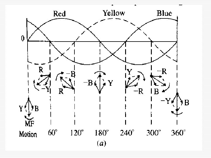
Speed of rotating magnetic field • The speed at which the rotating magnetic field revolves is called the synchronous speed (Ns). • The time instant 4 represents the completion of one-quarter cycle of alternating current Ix from the time instant 1. • During this one quarter cycle, the field has rotated through 90°. • At a time instant, one complete cycle of current Ix from the origin, the field has completed one revolution. • Therefore, for a 2 -pole stator winding, the field makes one revolution in one cycle of current. • In a 4 -pole stator winding, the rotating field makes one revolution in two cycles of current. In general, for P poles, the rotating field makes one revolution in P/2 cycles of current.
• The speed of the rotating magnetic field is the same as the speed of the alternator that is supplying power to the motor if the two have the same number of poles. • Hence the magnetic flux is said to rotate at synchronous speed.
Synchronous speed P 50 Hz 60 Hz 2 3000 3600 4 1500 1800 6 1000 1200 8 750 900 10 600 720 12 500 600
Direction of rotating magnetic field • The phase sequence of the three-phase voltage applied to the stator winding is X-Y-Z. • If this sequence is changed to X-Z-Y, it is observed that direction of rotation of the field is reversed i. e. , the field rotates counterclockwise rather than clockwise. • However, the number of poles and the speed at which the magnetic field rotates remain unchanged. • As we shall see, the rotor in a 3 -phase induction motor runs in the same direction as the rotating magnetic field. • Therefore, the direction of rotation of a 3 -phase induction motor can be reversed by interchanging any two of the three motor supply lines.
Operation
Operation (i) When 3 -phase stator winding is energized from a 3 -phase supply, a rotating magnetic field is set up which rotates round the stator at synchronous speed Ns (= 120 f/P). (ii) The rotating field passes through the air gap and cuts the stationary rotor conductors. Due to the relative speed between the rotating flux and the stationary rotor, e. m. f. s are induced in the rotor conductors. Since the rotor circuit is short-circuited, currents start flowing in the rotor conductors.
Operation (iii) The current-carrying rotor conductors are placed in the magnetic field produced by the stator. Consequently, mechanical force acts on the rotor conductors. The sum of the mechanical forces on all the rotor conductors produces a torque which tends to move the rotor in the same direction as the rotating field. (iv) According to this law, the direction of rotor currents will be such that they tend to oppose the cause producing them. Now, the cause producing the rotor currents is the relative speed between the rotating field and the stationary rotor conductors. Hence to reduce this relative speed, the rotor starts running in the same direction as that of stator field and tries to catch it.
Induction motor speed At what speed will the IM run? - - Can the IM run at the synchronous speed, why? If rotor runs at the synchronous speed, which is the same speed of the rotating magnetic field, then the rotor will appear stationary to the rotating magnetic field and the rotating magnetic field will not cut the rotor. So, no induced current will flow in the rotor and no rotor magnetic flux will be produced so no torque is generated and the rotor speed will fall below the synchronous speed When the speed falls, the rotating magnetic field will cut the rotor windings and a torque is produced
Induction motor speed So, the IM will always run at a speed lower than the synchronous speed The difference between the motor speed and the synchronous speed is called the Slip Where nslip= slip speed nsync= speed of the magnetic field nm = mechanical shaft speed of the motor
The Slip Where s is the slip (i) The quantity Ns N is sometimes called slip speed. (ii) When rotor runs at synchronous speed (i. e. , N = Ns), slip, s = 0 (iii) When the rotor is stationary (i. e. , N = 0), slip, s = 1 or 100 %. (iv) In an induction motor, the change in slip from no-load to full-load is hardly 0. 1% to 3% so that it is essentially a constant-speed motor.
Induction Motors and Transformers Both IM and transformer works on the principle of induced voltage - Transformer: voltage applied to the primary windings produce an induced voltage in the secondary windings Induction motor: voltage applied to the stator windings produce an induced voltage in the rotor windings The difference is that, in the case of the induction motor, the secondary windings can move Due to the rotation of the rotor (the secondary winding of the IM), the induced voltage in it does not have the same frequency of the stator (the primary) voltage
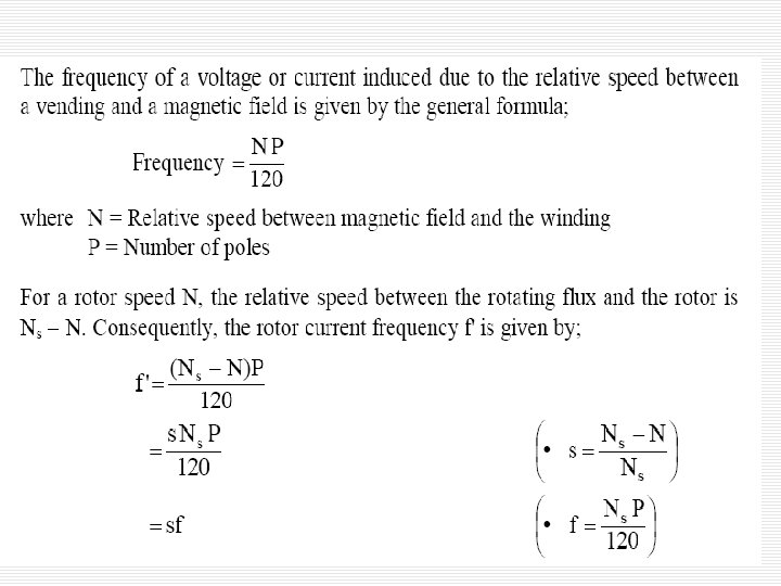
Rotor Current Frequency The frequency of the voltage induced in the rotor is given by Where fr = the rotor frequency (Hz) P = number of stator poles n = slip speed (rpm)
Frequency What would be the frequency of the rotor’s induced voltage at any speed nm? When the rotor is blocked (s=1) , the frequency of the induced voltage is equal to the supply frequency On the other hand, if the rotor runs at synchronous speed (s = 0), the frequency will be zero
Torque While the input to the induction motor is electrical power, its output is mechanical power and for that we should know some terms and quantities related to mechanical power Any mechanical load applied to the motor shaft will introduce a Torque on the motor shaft. This torque is related to the motor output power and the rotor speed and
Horse power Another unit used to measure mechanical power is the horse power It is used to refer to the mechanical output power of the motor Since we, as an electrical engineers, deal with watts as a unit to measure electrical power, there is a relation between horse power and watts
Example A 208 -V, 10 hp, four pole, 60 Hz, Y-connected induction motor has a full-load slip of 5 percent 1. 2. 3. 4. What is the synchronous speed of this motor? What is the rotor speed of this motor at rated load? What is the rotor frequency of this motor at rated load? What is the shaft torque of this motor at rated load?
Solution 1. 1.
Equivalent Circuit The induction motor is similar to the transformer with the exception that its secondary windings are free to rotate As we noticed in the transformer, it is easier if we can combine these two circuits in one circuit but there are some difficulties
Equivalent Circuit When the rotor is locked (or blocked), i. e. s =1, the largest voltage and rotor frequency are induced in the rotor, Why? On the other side, if the rotor rotates at synchronous speed, i. e. s = 0, the induced voltage and frequency in the rotor will be equal to zero, Why? Where ER 0 is the largest value of the rotor’s induced voltage obtained at s = 1(locked rotor)
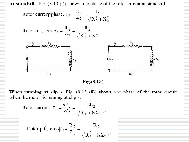
Effect of Slip on The Rotor Circuit • When the rotor is stationary, s = 1, the per phase rotor e. m. f. E 2 has a frequency equal to that of supply frequency f. • At any slip s, the relative speed between stator field and the rotor is decreased. • Consequently, the rotor e. m. f. and frequency are reduced proportionally to s. Es and sf respectively. • At the same time, per phase rotor reactance X 2, being frequency dependent, is reduced to s. X 2.
Equivalent Circuit Then, we can draw the rotor equivalent circuit as follows Where ER is the induced voltage in the rotor and RR is the rotor resistance
Equivalent Circuit The same is true for the frequency, i. e. It is known that So, as the frequency of the induced voltage in the rotor changes, the reactance of the rotor circuit also changes Where Xr 0 is the rotor reactance at the supply frequency (at blocked rotor)
Rotor Current • The rotor is assumed to be of wound type and star connected. • The rotor e. m. f. /phase and rotor reactance/phase are s. E 2 and s. X 2 respectively. • The rotor resistance/phase is R 2 and is independent of frequency and, therefore, does not depend upon slip. • Likewise, stator winding values R 1 and X 1 do not depend upon slip. • Since the motor represents a balanced 3 -phase load, we need consider one phase only; the conditions in the other two phases being similar.
Equivalent Circuit Now we can calculate the rotor current as Dividing both the numerator and denominator by s so nothing changes we get Where ER 0 is the induced voltage and XR 0 is the rotor reactance at blocked rotor condition (s = 1)
Equivalent Circuit Now we can have the rotor equivalent circuit
Equivalent Circuit Now as we managed to solve the induced voltage and different frequency problems, we can combine the stator and rotor circuits in one equivalent circuit
Power losses in Induction machines Copper losses - Copper loss in the stator (PSCL) = I 12 R 1 Copper loss in the rotor (PRCL) = I 22 R 2 Core loss (Pcore) Mechanical power loss due to friction and windage How this power flow in the motor?
Power flow in induction motor
Power Stages in an Induction Motor The input electric power fed to the stator of the motor is converted into mechanical power at the shaft of the motor. The various losses during the energy conversion are: 1. Fixed losses (i) Stator iron loss (ii) Friction and windage loss The rotor iron loss is negligible because the frequency of rotor currents under normal running condition is small. 2. Variable losses (i) Stator copper loss (ii) Rotor copper loss
(i) Stator inpur, Pi = Stator output +Stator losses (Iron loss + Cu loss) (ii) Rotor input, Pr = Stator output Stator o/p is transferred to rotor through airgap by electromagnetic induction. (iii) Mechanical power available, Pm = Pr - Rotor Cu loss Mech. power available is the gross rotor o/p & will produce a gross torque Tg. (iv) Mechanical power at shaft, Pout = Pm - Friction and windage loss Mechanical power available at the shaft produces a shaft torque Tsh.
Induction Motor Torque Note. Since windage and friction loss is small, Tg = Tsh, . This assumption hardly leads to any significant error.
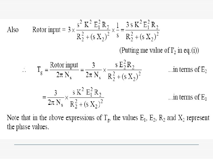
Rotor Output If Tg newton-metre is the gross torque developed and N r. p. m. is the speed of the rotor, then, If there were no copper losses in the rotor, the output would equal rotor input and the rotor would run at synchronous speed Ns.
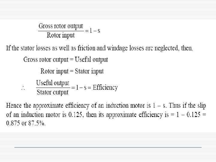
It is clear that if the input power to rotor is Pr then s Pr is lost as rotor Cu loss and the remaining (1 - s)Pr is converted into mechanical power. Consequently, induction motor operating at high slip has poor efficiency.
Power relations
Power relations
Power relations 1 1 -s s
Equivalent Circuit We can rearrange the equivalent circuit as follows Actual rotor resistance Resistance equivalent to mechanical load
Induction Motor Torque Equation The gross torque Tg developed by an induction motor is given by;
Example A 480 -V, 60 Hz, 50 -hp, three phase induction motor is drawing 60 A at 0. 85 PF lagging. The stator copper losses are 2 k. W, and the rotor copper losses are 700 W. The friction and windage losses are 600 W, the core losses are 1800 W, and the stray losses are negligible. Find the following quantities: – – – 1. The air-gap power PAG. The power converted Pconv. The output power Pout. The efficiency of the motor.
Solution 1. 1.
Solution 1.
Example A 460 -V, 25 -hp, 60 Hz, four-pole, Y-connected induction motor has the following impedances in ohms per phase referred to the stator circuit: R 1= 0. 641 R 2= 0. 332 X 1= 1. 106 X 2= 0. 464 XM= 26. 3 The total rotational losses are 1100 W and are assumed to be constant. The core loss is lumped in with the rotational losses. For a rotor slip of 2. 2 percent at the rated voltage and rated frequency, find the motor’s 1. 2. 3. Speed Stator current Power factor • Pconv and Pout • ind and load 1. Efficiency
Solution 1.
Solution 1. 2.
Solution 1.
Torque-speed characteristics Typical torque-speed characteristics of induction motor
Comments • • • The induced torque is zero at synchronous speed. Discussed earlier. The curve is nearly linear between no-load and full load. In this range, the rotor resistance is much greater than the reactance, so the rotor current, torque increase linearly with the slip. There is a maximum possible torque that can’t be exceeded. This torque is called pullout torque and is 2 to 3 times the rated full-load torque.
Comments • • • The starting torque of the motor is slightly higher than its full-load torque, so the motor will start carrying any load it can supply at full load. The torque of the motor for a given slip varies as the square of the applied voltage. If the rotor is driven faster than synchronous speed it will run as a generator, converting mechanical power to electric power.
Complete Speed-torque c/c
Maximum torque occurs when the power transferred to R 2/s is maximum. This condition occurs when R 2/s equals the magnitude of the impedance RTH + j (XTH + X 2)
Maximum torque The corresponding maximum torque of an induction motor equals The slip at maximum torque is directly proportional to the rotor resistance R 2 The maximum torque is independent of R 2
Maximum torque Rotor resistance can be increased by inserting external resistance in the rotor of a wound-rotor induction motor. The value of the maximum torque remains unaffected but the speed at which it occurs can be controlled.
Maximum torque Effect of rotor resistance on torque-speed characteristic
Determination of motor parameters Due to the similarity between the induction motor equivalent circuit and the transformer equivalent circuit, same tests are used to determine the values of the motor parameters. - - DC test: determine the stator resistance R 1 No-load test: determine the rotational losses and magnetization current (similar to no-load test in Transformers). Locked-rotor test: determine the rotor and stator impedances (similar to short-circuit test in Transformers).
DC test - - The purpose of the DC test is to determine R 1. A variable DC voltage source is connected between two stator terminals. The DC source is adjusted to provide approximately rated stator current, and the resistance between the two stator leads is determined from the voltmeter and ammeter readings.
DC test - then - If the stator is Y-connected, the per phase stator resistance is - If the stator is delta-connected, the per phase stator resistance is
No-load test 1. The motor is allowed to spin freely – The only load on the motor is the friction and windage losses, so all Pconv is consumed by mechanical losses 1. The slip is very small
No-load test – At this small slip The equivalent circuit reduces to…
No-load test – Combining Rc & RF+W we get……
No-load test - At the no-load conditions, the input power measured by meters must equal the losses in the motor. The PRCL is negligible because I 2 is extremely small because R 2(1 -s)/s is very large. The input power equals Where
No-load test 1. The equivalent input impedance is thus approximately If X 1 can be found, in some other fashion, the magnetizing impedance XM will be known
Blocked-rotor test • In this test, the rotor is locked or blocked so that it cannot move, a voltage is applied to the motor, and the resulting voltage, current and power are measured.
Blocked-rotor test • The AC voltage applied to the stator is adjusted so that the current flow is approximately full-load value. • The locked-rotor power factor can be found as • The magnitude of the total impedance
Blocked-rotor test Where X’ 1 and X’ 2 are the stator and rotor reactances at the test frequency respectively
Tests To Determine The Equivalent Circuit No‑load test
Locked‑rotor test
Blocked‑rotor equivalent circuit for improved value for