Chapter Five PRESSURE VESSEL INTRODUCTION The pressure vessels

 are used to store")

 energy")


")


 and (ii),")


 The vessel under wind loading acts as a cantilever beam.")
 Dynamic wind pressure The load imposed on any structure by")
 A wind speed of 160 km/h (100 mph) can be")

- Slides: 54
Chapter Five PRESSURE VESSEL
INTRODUCTION § The pressure vessels (i. e. cylinders or tanks) are used to store fluids under pressure. § The pressure vessels are designed with great care because rupture of a pressure vessel means an explosion which may cause loss of life and property. § The material of pressure vessels may be brittle such as cast iron, or ductile such as mild steel. 2
• They are used in a variety of industries like § Petroleum refining § Chemical § Power § Food & beverage § Pharmaceutical 3
Reactor: • The reactor is used to convert nuclear (also known as 'atomic') energy into heat. While a reactor could be one in which heat is produced by fusion or radioactive decay. • In a nuclear power plant, the reactor vessel is a pressure vessel containing the coolant and reactor core. • It is a device for containing and controlling a chemical reaction. The chemical process enables to convert raw material into final product under given pressure and temperature. 4
5
Classification of Pressure Vessels According to the dimensions: The pressure vessels, according to their dimensions, may be classified as thin shell or thick shell. ØIf the wall thickness of the shell (t) is less than 1/10 of the diameter of the shell (d), then it is called a thin shell. ØIf the wall thickness of the shell is greater than 1/10 of the diameter of the shell, then it is said to be a thick shell. 6
According to the end construction: The pressure vessels, according to the end construction, may be classified as open end or closed end. A simple cylinder with a piston, such as cylinder of a press is an example of an open end vessel, whereas a tank is an example of a closed end vessel. 7
There are three main types of pressure vessels in general ØHorizontal Pressure Vessels ØVertical Pressure Vessels ØSpherical Pressure vessels However there are some special types of Vessels like Regeneration Tower, Reactors but these names are given according to their use only. 8
HORIZONTAL PRESSURE VESSEL 9
VERTICAL PRESSURE VESSEL 10
SPHERICAL PRESSURIZED STORAGE VESSEL 11
MAIN COMPONENTS OF PRESSURE VESSEL • The main pressure vessel components are: ü Shell ü Head ü Nozzle ü Support 12
Shell Ø The shell is the primary component that contains the pressure. Ø Pressure vessel shells are welded together to form a structure that has a common rotational axis. Ø Most pressure vessel shells are cylindrical, spherical and conical in shape. 13
Head Ø All pressure vessel shells must be closed at the ends by heads (or another shell section). Ø Heads are typically curved rather than flat. Ø Curved configurations are stronger and allow the heads to be thinner, lighter, and less expensive than flat heads. Ø Heads can also be used inside a vessel. Ø Heads are usually categorized by their shapes. Ellipsoidal, Hemispherical, Torispherical, Conical, Toriconical and flat are the common types of heads. Ellipsoidal (2: 1) would be the most common type of heads, which is used during the designing of pressure vessels. 14
Types of Heads 15
Nozzle A nozzle is a cylindrical component that penetrates the shell or heads of a pressure vessel. The nozzle ends are usually flanged to allow for the necessary connections and to permit easy disassembly for maintenance or access. Nozzles are used for the following applications: § Attach piping for flow into or out of the vessel. § Attach instrument connections, (e. g. , level gauges or pressure gauges). § Provide access to the vessel interior at manways. § Provide for direct attachment of other equipment items, (e. g. , a heat exchanger or mixer). 16
Support The type of support that is used depends primarily on the size and orientation of the pressure vessel. In all cases, the pressure vessel support must be adequate for the applied weight, wind, and earthquake loads. Typical kinds of supports are as follow: Ø Saddle Ø Leg Ø Skirt Ø Lug 17
Saddle ØHorizontal drums are typically supported at two locations by saddle supports. ØA saddle support spreads the weight load over a large area of the shell to prevent an excessive local stress in the shell at the support points. ØThe width of the saddle, among other design details, is determined by the specific size and design conditions of the pressure vessel. One saddle support is normally fixed or anchored to its foundation. ØThe other support is normally free to permit unrestrained longitudinal thermal expansion of the drum. 18
A typical scheme of saddle support 19
Leg Ø Small vertical drums are typically supported on legs that are welded to the lower portion of the shell. Ø The maximum ratio of support leg length to drum diameter is typically 2: 1. ØThe number of legs needed depends on the drum size and the loads to be carried. ØSupport legs are also typically used for spherical pressurized storage vessels. ØThe support legs for small vertical drums and spherical pressurized storage vessels may be made from structural steel columns or pipe sections, whichever provides a more efficient design. ØCross bracing between the legs is typically used to help absorb wind or earthquake loads. 20
Skirt Ø Tall, vertical, cylindrical pressure vessels (e. g. , the tower and reactor) are typically supported by skirts. Ø A support skirt is a cylindrical shell section that is welded either to the lower portion of the vessel shell or to the bottom head (for cylindrical vessels). ØSkirts for spherical vessels are welded to the vessel near the mid-plane of the shell. The skirt is normally long enough to provide enough flexibility so that radial thermal expansion of the shell does not cause high thermal stresses at its junction with the skirt 21
Lug ØLugs that are welded to the pressure vessel shell and used to support vertical pressure vessels. ØThe use of lugs is typically limited to vessels of small to medium diameter (1 to 10 ft. ) and moderate height-to-diameter ratios in the range of 2: 1 to 5: 1. ØLug supports are often used for vessels of this size that are located above grade within structural steel. ØThe lugs are typically bolted to horizontal structural members to provide stability against overturning loads; however, the bolt holes are often slotted to permit free radial thermal expansion of the drum 22
Typical Scheme of lug 23
Thin Cylindrical Shell under Internal Pressure The analysis of stresses induced in a thin cylindrical shell are made on the following assumptions: Ø The effect of curvature of the cylinder wall is neglected. Ø The tensile stresses are uniformly distributed over the section of the walls. Ø The effect of the restraining action of the heads at the end of the pressure vessel is neglected. When a thin cylindrical shell is subjected to an internal pressure, it is likely to fail in the following two ways: Ø It may fail along the longitudinal section (i. e. circumferentially) splitting the cylinder into two troughs, as shown in Fig. a. Ø It may fail across the transverse section (i. e. longitudinally) splitting the cylinder into two cylindrical shells, as shown in Fig. b. 24
Failure of a cylindrical shell 25
Circumferential or Hoop Stress A tensile stress acting in a direction tangential to the circumference is called circumferential or hoop stress. In other words, it is a tensile stress on longitudinal section (or on the cylindrical walls). 26
Total force acting on longitudinal section Total resisting force acting on the cylinder walls From equations (i) and (ii), we have 27
Longitudinal Stress A tensile stress acting in the direction of the axis is called longitudinal stress. In other words, it is a tensile stress acting on the transverse or circumferential section Y-Y (or on the ends of the vessel). 28
Total force acting on transverse section Total resisting force From equations (i) and (ii), we have 29
Thick Cylindrical Shell under Internal Pressure When a cylindrical shell of a pressure vessel, hydraulic cylinder, gun barrel and a pipe is subjected to a very high internal fluid pressure, then the walls of the cylinder must be made extremely heavy or thick. In thin cylindrical shells, we have assumed that the tensile stresses are uniformly distributed over the section of the walls. But in the case of thick wall cylinders, the stress over the section of the walls cannot be assumed to be uniformly distributed. They develop both tangential and radial stresses with values which are dependent upon the radius of the element under consideration. The distribution of stress in a thick cylindrical shell, the tangential stress is maximum at the inner surface and minimum at the outer surface of the shell. The radial stress is maximum at the inner surface and zero at the outer surface of the shell. 30
Stress distribution in thick cylindrical shells subjected to internal pressure 31
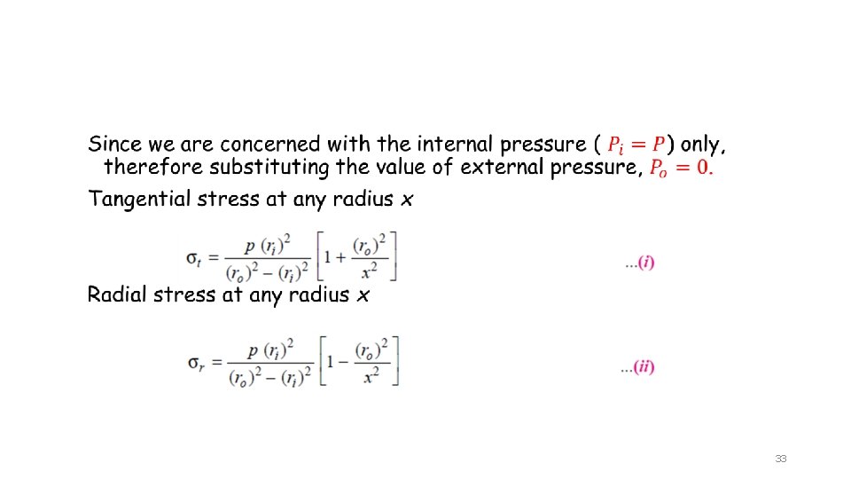
Lame’s equation. Assuming that the longitudinal fibers of the cylindrical shell are equally strained, Lame has shown that the tangential stress at any radius x is: and radial stress at any radius x 32
The tangential stress is always a tensile stress whereas the radial stress is a compressive stress. The tangential stress is maximum at the inner surface of the shell (i. e. when x = ri ) and it is minimum at the outer surface of the shell (i. e. when x = ro). Substituting the value of x = ri and x = ro in equation (i), we find that the maximum tangential stress at the inner surface of the shell. Minimum tangential stress at the outer surface of the shell 34
The radial stress is maximum at the inner surface of the shell and zero at the outer surface of the shell. Substituting the value of x = ri and x = ro in equation (ii). Maximum radial stress at the inner surface of the shell Minimum radial stress at the outer surface of the shell 35
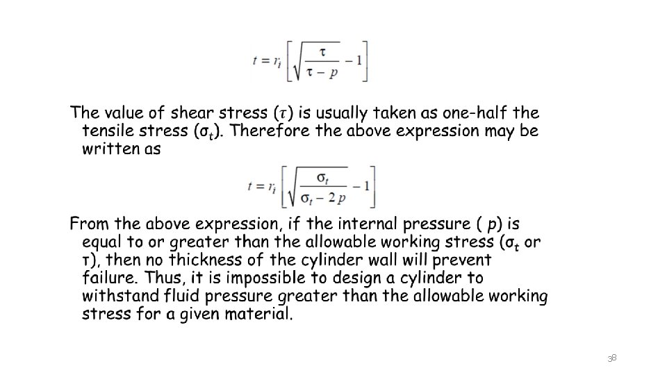
In designing a thick cylindrical shell of brittle material (e. g. cast iron, hard steel and cast aluminum) with closed or open ends and in accordance with the maximum normal stress theory failure, the tangential stress induced in the cylinder wall Since ro = ri + t, therefore substituting this value of ro in the above expression: The value of σt for brittle materials may be taken as 0. 125 times the ultimate tensile strength (σu). 36
In case of cylinders made of ductile material, Lame’s equation is modified according to maximum shear stress theory. Maximum principal stress at the inner surface Minimum principal stress at the outer surface Maximum shear stress 37
OPTIMUM VESSEL PROPORTIONS V =vessel volume, cu ft P = internal pressure, PSl. G L=length, ft D =diameter, ft C =corrosion allowance, in. F 2 =vessel ratios S =allowable stress, psi E =joint efficiency 39
OPTIMUM VESSEL PROPORTIONS Method 1. Calculate F 2. 2. From Figure determine L/D ratio. 3. From the L/D ratio, calculate the diameter, D. 4. Use D and V to calculate the required length, L. 40
41
External pressure ØExternal pressure on cylindrical shells causes compressive forces that could lead to buckling. Ø The equations for the buckling of cylindrical shells under external pressure are extremely cumbersome to use directly in design (Jawad, 1994). However, these equations can be simplified for design purposes by plotting them so that the minimum buckling strain is expressed in terms of length, diameter and thickness of the cylinder. These plots are utilized by the ASME. 42
For an open-ended cylinder, the critical pressure to cause buckling Pc is given by the following expression; Windenburg and Trilling (1934): 43
44
45
The value of S is taken as the smaller of two times the allowable tensile stress, or 0. 9 times the yield stress of the material at the design temperature. 46
47
48
Weight loads The major sources of dead weight loads are: 1. The vessel shell. 2. The vessel fittings: manways, nozzles. 3. Internal fittings: plates (plus the fluid on the plates); heating and cooling coils. 4. External fittings: ladders, platforms, piping. 5. Auxiliary equipment which is not self-supported; condensers, agitators. 6. Insulation. 7. The weight of liquid to fill the vessel 49
Weight loads The approximate weight of a cylindrical vessel with domed ends, and uniform wall thickness, can be estimated from the following equation: For a steel vessel 50
Wind Loads (Tall Vessels) The vessel under wind loading acts as a cantilever beam. For a uniformly loaded cantilever the bending moment at any plane is given by: where x is the distance measured from the free end and w the load per unit length (Newtons per meter run). 51
Wind Loads (Tall Vessels) Dynamic wind pressure The load imposed on any structure by the action of the wind will depend on the shape of the structure and the wind velocity. 52
Wind Loads (Tall Vessels) A wind speed of 160 km/h (100 mph) can be used for preliminary design studies; equivalent to a wind pressure of 1280 N/m 2 (25 lb/ft 2). The loading per unit length of the column can be obtained from the wind pressure by multiplying by the effective column diameter: the outside diameter plus an allowance for thermal insulation and attachments, such as pipes and ladders. 53
Stresses Analysis Pressure stresses: Dead weight stress: Bending stresses: 54