UNIVERSITI MALAYSIA PERLIS EKT 2414 ELECTROMAGNETIC THEORY CHAPTER


")


 inner conductor radius = r")


")


 a hard")


 az")
 H 1 t = H 2 t thus, H 2")


: • i. e magnetic energy per")

- Slides: 63
UNIVERSITI MALAYSIA PERLIS EKT 241/4: ELECTROMAGNETIC THEORY CHAPTER 4 – MAGNETOSTATICS
Chapter Outline • • • Maxwell’s Equations Magnetic Forces and Torques The total electromagnetic force, known as Lorentz force Biot- Savart’s law Gauss’s law for magnetism Ampere’s law for magnetism Magnetic Field and Flux Vector magnetic potential Properties of 3 different types of material Boundary conditions between two different media Self inductance and mutual inductance Magnetic energy
Maxwell’s equations: Where; E = electric field intensity D = electric flux density ρv = electric charge density per unit volume H = magnetic field intensity B = magnetic flux density
Maxwell’s equations • For static case, ∂/∂t = 0. • Maxwell’s equations is reduced to: Electrostatics Magnetostatics
Magnetic Force B = Magnetic Flux Density B B q q q B I B
Magnetic Torque on a Current. Carrying Loop • Applied force vector F and distance vector d are used to generate a torque T T = d× F (N·m) • Rotation direction is governed by right-hand rule.
Magnetic Forces and Torques • The electric force Fe per unit charge acting on a test charge placed at a point in space with electric field E. • When a charged particle moving with a velocity u passing through that point in space, the magnetic force Fm is exerted on that charged particle. where B = magnetic flux density (Cm/s or Tesla T)
Magnetic Forces and Torques • If a charged particle is in the presence of both an electric field E and magnetic field B, the total electromagnetic force acting on it is:
Magnetic Force on a Current. Carrying Conductor • For closed circuit of contour C carrying I , total magnetic force Fm is: • In a uniform magnetic field, Fm is zero for a closed circuit.
Magnetic Force on a Current. Carrying Conductor • On a line segment, Fm is proportional to the vector between the end points.
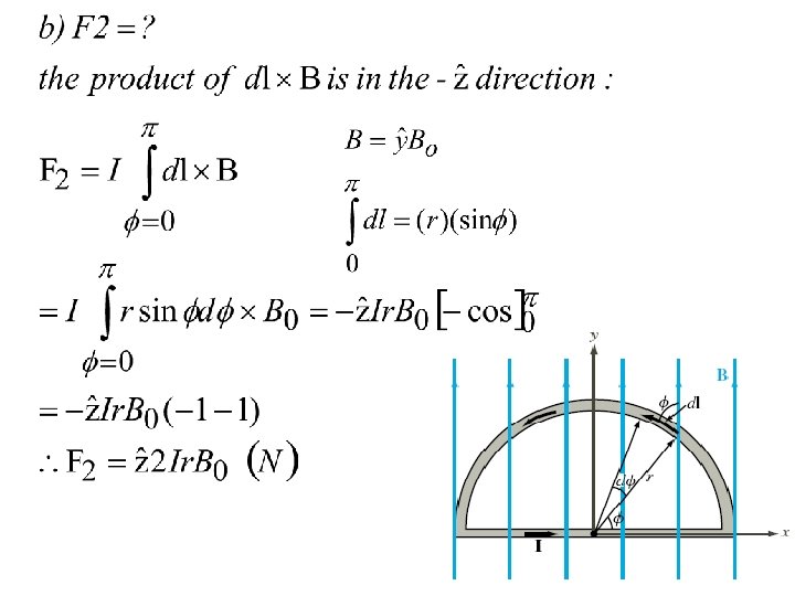
Example 1 The semicircular conductor shown carries a current I. The closed circuit is exposed to a uniform magnetic field. Determine (a) the magnetic force F 1 on the straight section of the wire and (b) the force F 2 on the curved section.
Solution to Example 1 • a)
The Biot–Savart’s Law The Biot–Savart law is used to compute the magnetic field generated by a steady current, i. e. a continual flow of charges, for example through a wire Biot–Savart’s law states that: where: d. H = differential magnetic field = differential length dl
The Biot–Savart’s Law • To determine the total H:
The Biot–Savart’s Law • Biot–Savart’s law may be expressed in terms of distributed current sources.
Example 2 Determine the magnetic field at the apex O of the pie-shaped loop as shown. Ignore the contributions to the field due to the current in the small arcs near O.
O A = dl C O = -dl A C ? • For segment AC, dl is in φ direction, • Using Biot- Savart’s law: 0
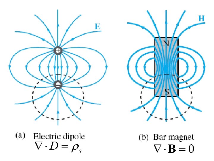
Gauss’s Law for Magnetism • Gauss’s law for magnetism states that: • Magnetic field lines always form continuous closed loops.
Ampere’s law for magnetism • Ampere’s law states that: • true for an infinite length of conductor H dl true for an infinite length of conductor C, +aø I, +az r
Magnetic Field of an infinite length of conductor From terms of Hφ: then re-arrange the equation in Hence, the magnetic field vector, H:
If we have a wire : pg 259 buku If we have a wire :
Example 3 • A toroidal coil with N turns carrying a current I , determine the magnetic field H in each of the following three regions: r < a, a < r < b, and r > b, all in the azimuthal plane of the toroid.
Solution to Example 3 • H = 0 for r < a as no current is flowing through the surface of the contour • H = 0 for r > b, as equal number of current coils cross the surface in both directions. • For a < r < b, we apply Ampere’s law: • Hence, H = NI/(2πr).
Magnetic Flux • The amount of magnetic flux, φ in Webers from magnetic field passing through a surface is found in a manner analogous to finding electric flux:
Example 4 An infinite length coaxial cable with inner conductor radius of 0. 01 m and outer conductor radius of 0. 05 m carrying a current of 2. 5 A exists along the z axis in the + az direction. Find the flux passing through the region between two conductors with height of 2 m in free space.
Solution to Example 4 Iaz=2. 5 A z 1) inner conductor radius = r 1 0. 01 m 2) outer conductor radius = r 2 0. 05 m 3) current of 2. 5 A (in the +az direction) 4) Flux radius = 2 m aø Flux, z xy r 2 r 1
Solution to Example 4 where d. S is in the aø direction. So, Therefore,
Vector Magnetic Potential • For any vector of vector magnetic potential A: • We are able to derive: . • Vector Poisson’s equation is given as: where
Magnetic Properties of Materials Diamagnetic Paramagnetic Ferromagnetic The behavior of magnetic dipole moments & magnetic susceptibility, of its atoms with an external magnetic field is used as a basis for classifying magnetic materials.
Magnetic Properties of Materials • Magnetization in a material is associated with atomic current loops generated by two principal mechanisms: – Orbital motions of the electrons around the nucleus, i. e orbital magnetic moment, mo – Electron spin about its own axis, i. e spin magnetic moment, ms
Magnetic Permeability • Magnetization vector M is defined as where = magnetic susceptibility (dimensionless) • Magnetic permeability is defined as: and to define the magnetic properties in term of relative permeability is defined as:
Magnetic Materials – Diamagnetic q metals have a very weak and negative susceptibility ( ) to magnetic field q slightly repelled by a magnetic field and the material does not retain the magnetic properties when the external field is removed q Most elements in the periodic table, including copper, silver, and gold, are diamagnetic.
Magnetic Materials Paramagnetic Ø Paramagnetic materials have a small and positive susceptibilities to magnetic fields. Ø slightly attracted by a magnetic field and the material does not retain the magnetic properties when the external field is removed. Ø Paramagnetic materials include magnesium, molybdenum, lithium, and tantalum.
Magnetic Materials – Diamagnetic, Paramagnetic • However, the absolute susceptibilities value of both materials is in the order 10 -5. Thus, can be ignored. Hence, we have Magnetic permeability: • Diamagnetic and paramagnetic materials include dielectric materials and most metals.
Magnetic Materials – Ferromagnetic Materials • Ferromagnetic materials is characterized by magnetized domain - a microscopic region within which the magnetic moments of all its atoms are aligned parallel to each other. • Hysteresis – “to lag behind”. It determines how easy/hard for a magnetic material to be magnetized and demagnetized.
Process of Magnetic Hysteresis material is magnetized and can serve as permanent magnet! B material is demagnetize
Magnetic Hysteresis of Ferromagnetic Materials • Comparison of hysteresis curves for (a) a hard and (b) a soft ferromagnetic material is shown. Hard magnetic material- cannot be easily magnetized & demagnetized by an external magnetic field. Soft magnetic material – easily magnetized & demagnetized.
Magnetic Hysteresis of Ferromagnetic Materials • Properties of magnetic materials as follows:
Magnetic boundary conditions • Boundary between medium 1 with μ 1 and medium 2 with μ 2
Magnetic boundary conditions • Boundary condition related to normal components of the electric field; • By analogy, application of Gauss’s law for magnetism, we get first boundary condition: • Since , • For linear, isotropic media, the first boundary condition which is related to H;
z xy By applying Ampere’s law
STOPMagnetic boundary conditions • The result is generalized to a vector form: • Where • However, surface currents can exist only on the surfaces of perfect conductors and perfect superconductors (infinite conductivities). • Hence, at the interface between media with finite conductivities, Js=0. Thus:
Example xy (plane) az
• Solution: 1) H 1 t = H 2 t thus, H 2 t = 6 ax + 2 ay 2) Hn 1 = 3 az, but, Hn 2 = ? ? μr 1 = 6000 ; μr 2 = 3000 ; 6000μ 0(3 az) = 3000 μ 0(Hn 2) Hn 2 = 6 az thus, H 2 =6 ax + 2 ay + 6 az
Inductance • An inductor is the magnetic analogue of an electrical capacitor. • Capacitor can store electric energy in the electric field present in the medium between its conducting surfaces. • Inductor can store magnetic energy in the volume comprising the inductors.
Solenoid calculate magnetic field in solenoid Self inductance: is the ratio of the magnetic flux linkage, Λ to the current I flowing through the structure. INDUCTANCE store magnetic energy Calculate Magnetic Energy Mutual inductance: produced by magnetic coupling between two different conducting structures.
Inductance • Example of an inductor is a solenoid - a coil consisting of multiple turns of wire wound in a helical geometry around a cylindrical core.
Magnetic Field in a Solenoid • For one cross section of solenoid, • When l >a, θ 1≈− 90° and θ 2≈90°, Where, N=nl =total number of turns over the length l
Self Inductance The self-inductance of a circuit is used to describe the reaction of the circuit to a changing current in the circuit, (The ratio of the magnetic flux to the current)
Self Inductance • Self-inductance of any conducting structure is the ratio of the magnetic flux linkage, Λ to the current I flowing through the structure. • Magnetic flux linkage, Λ is the total magnetic flux linking a given conducting structure.
Self Inductance • Magnetic flux, linking a surface S is given by: • In a solenoid with uniform magnetic field, the flux linking a single loop is:
Self Inductance – magnetic flux in solenoid
Self Inductance • Magnetic flux, linking a surface S is given by: • In a solenoid with uniform magnetic field, the flux linking a single loop is:
Self Inductance • For a solenoid: • For two conductor configuration:
Self Inductance for a solenoid Thus,
Mutual Inductance • Mutual inductance – produced by magnetic coupling between two different conducting structures.
Mutual Inductance • Magnetic field B 1 generated by current I 1 results in a flux Φ 12 through loop 2: • If loop 2 consists of N 2 turns all coupled by B 1 in exactly the same way, the total magnetic flux linkage through loop 2 due to B 1 is:
Mutual Inductance stop here • Hence, the mutual inductance:
Magnetic Energy tahun 4 • Consider an inductor with an inductance L connected to a current source. • The current I flowing through the inductor is increased from zero to a final value I. • The energy expended in building up the current in the inductor: • i. e the magnetic energy stored in the inductor
Magnetic Energy • Magnetic energy density (for solenoid): • i. e magnetic energy per unit volume • Magnetic energy in magnetic field:
Example: Magnetic Energy in a Coaxial Cable • Derive an expression for the magnetic energy stored in a coaxial cable of length l and inner and outer a and b. The insulation material has magnetic permeability μ.