PGT 320 POWER ELECTRONICS UNIVERSITI MALAYSIA PERLIS FACULTY

- Slides: 26
PGT 320 - POWER ELECTRONICS UNIVERSITI MALAYSIA PERLIS FACULTY OF ENGINEERING TECHNOLOGY WEEK 3 THYRISTOR Khairul Affendi Rosli, MSc
Objectives To learn the design parameter of power thyristor (SCR) in details. To learn the protection of Power Electronics Devices. �Overcurrent �Overvoltage
Contents Design parameter of power thyristor (SCR) in details. Protection of Power Electronics Devices. �Overcurrent �Overvoltage
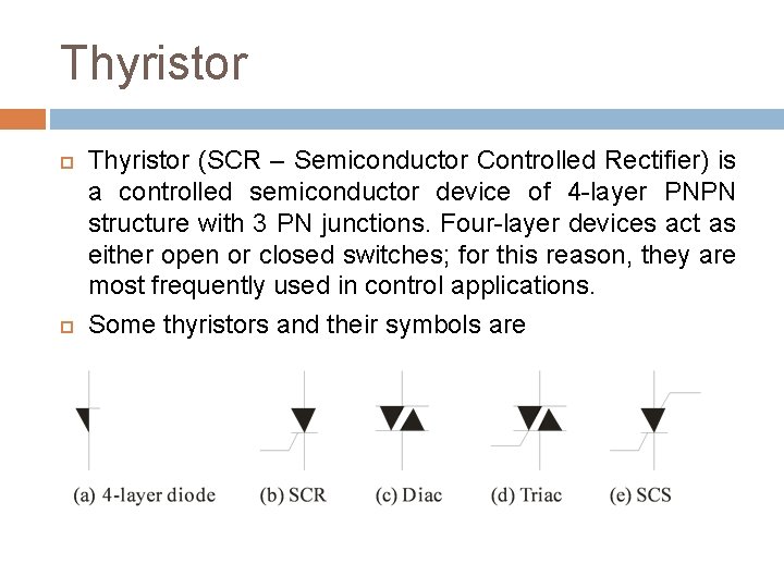
Thyristor (SCR – Semiconductor Controlled Rectifier) is a controlled semiconductor device of 4 -layer PNPN structure with 3 PN junctions. Four-layer devices act as either open or closed switches; for this reason, they are most frequently used in control applications. Some thyristors and their symbols are
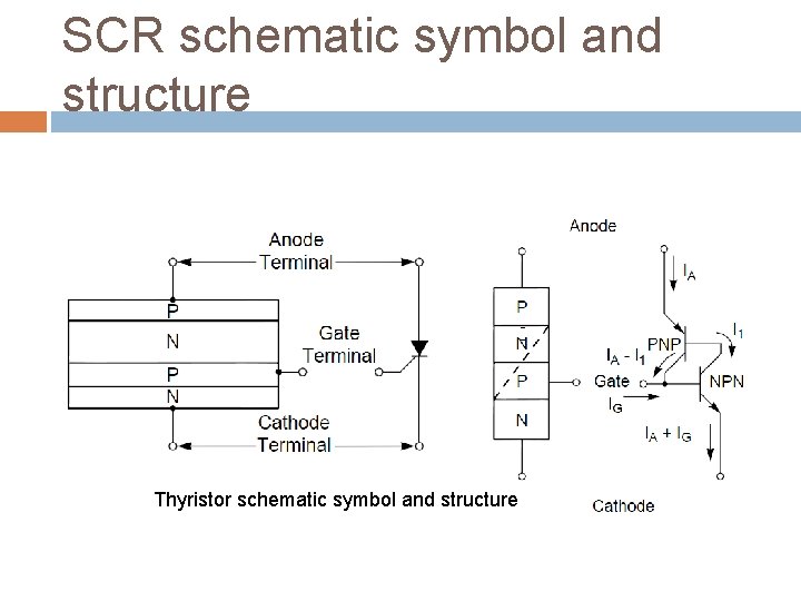
SCR schematic symbol and structure Thyristor schematic symbol and structure
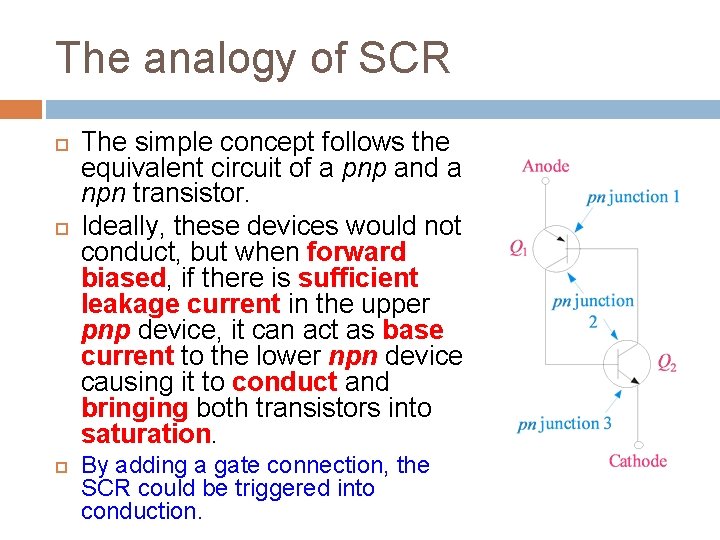
The analogy of SCR The simple concept follows the equivalent circuit of a pnp and a npn transistor. Ideally, these devices would not conduct, but when forward biased, if there is sufficient leakage current in the upper pnp device, it can act as base current to the lower npn device causing it to conduct and bringing both transistors into saturation. By adding a gate connection, the SCR could be triggered into conduction.
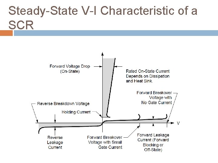
Steady-State V-I Characteristic of a SCR
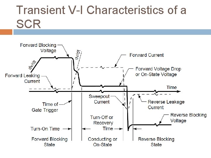
Transient V-I Characteristics of a SCR
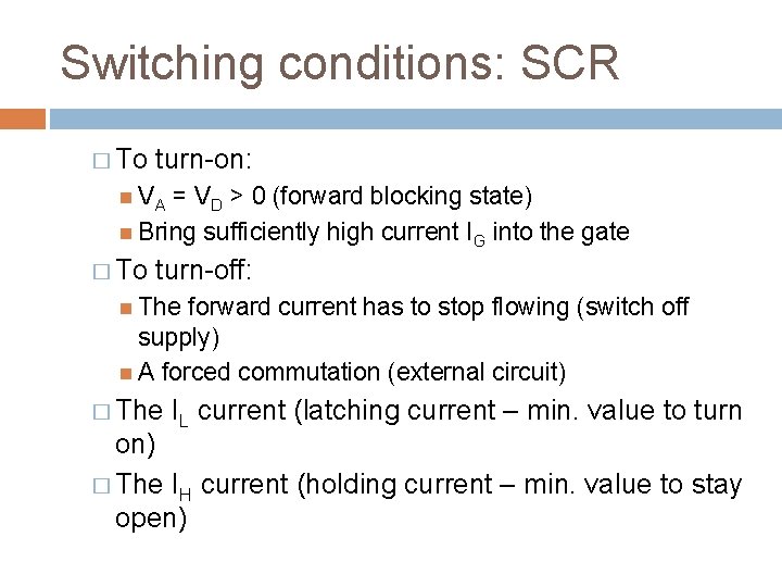
Switching conditions: SCR � To turn-on: VA = VD > 0 (forward blocking state) Bring sufficiently high current IG into the gate � To turn-off: The forward current has to stop flowing (switch off supply) A forced commutation (external circuit) � The IL current (latching current – min. value to turn on) � The IH current (holding current – min. value to stay open)
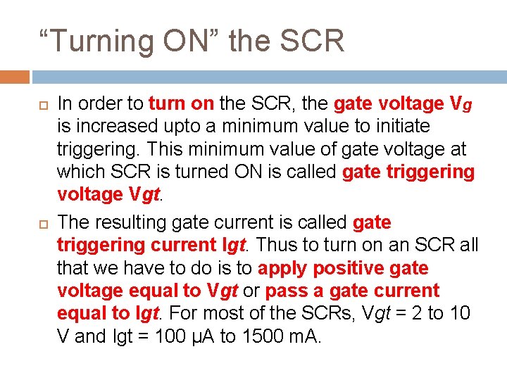
“Turning ON” the SCR In order to turn on the SCR, the gate voltage Vg is increased upto a minimum value to initiate triggering. This minimum value of gate voltage at which SCR is turned ON is called gate triggering voltage Vgt. The resulting gate current is called gate triggering current Igt. Thus to turn on an SCR all that we have to do is to apply positive gate voltage equal to Vgt or pass a gate current equal to Igt. For most of the SCRs, Vgt = 2 to 10 V and Igt = 100 µA to 1500 m. A.
“Turning OFF” the SCR The SCR turn-off poses more problems than SCR turn-on. It is because once the device is ON, the gate loses all control. There are many methods of SCR turn-off but only two will be discussed. � (i) Anode current interruption. � (ii) Forced commutation.
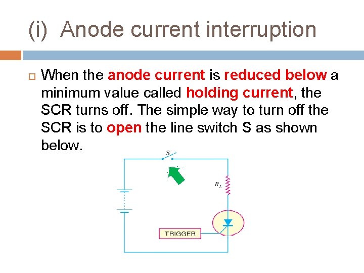
(i) Anode current interruption When the anode current is reduced below a minimum value called holding current, the SCR turns off. The simple way to turn off the SCR is to open the line switch S as shown below.
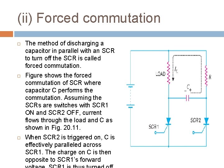
(ii) Forced commutation The method of discharging a capacitor in parallel with an SCR to turn off the SCR is called forced commutation. Figure shows the forced commutation of SCR where capacitor C performs the commutation. Assuming the SCRs are switches with SCR 1 ON and SCR 2 OFF, current flows through the load and C as shown in Fig. 20. 11. When SCR 2 is triggered on, C is effectively paralleled across SCR 1. The charge on C is then opposite to SCR 1’s forward
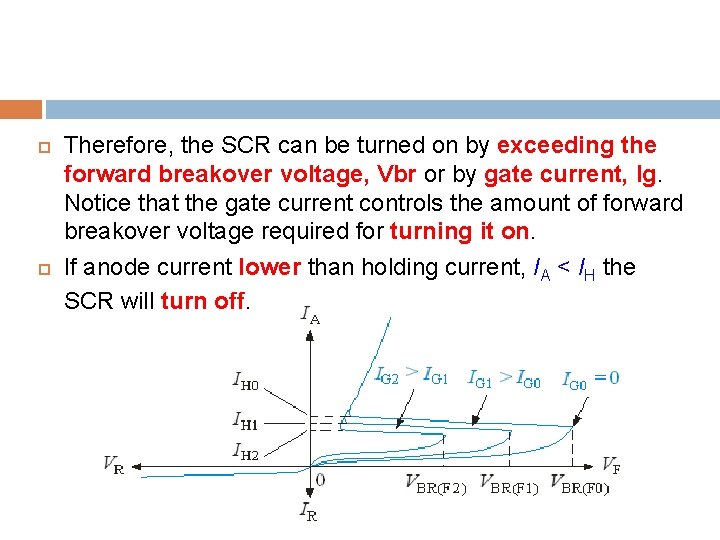
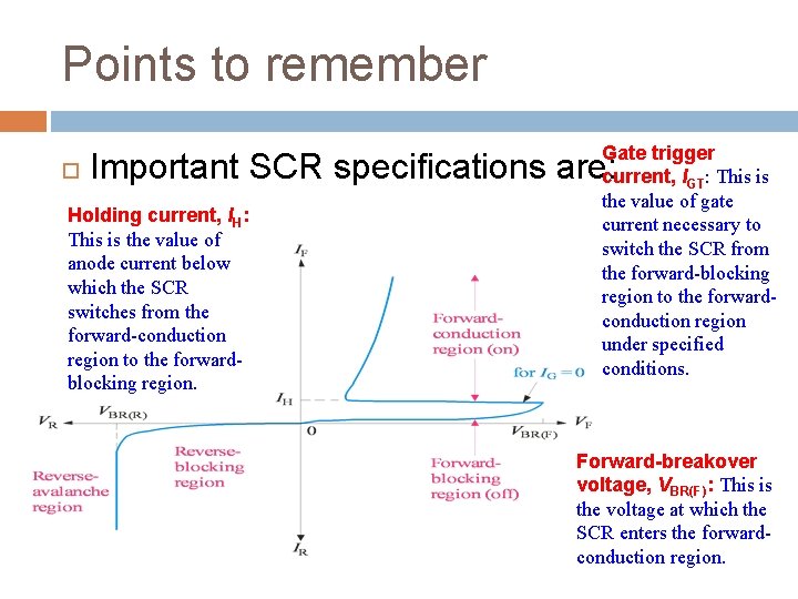
Therefore, the SCR can be turned on by exceeding the forward breakover voltage, Vbr or by gate current, Ig. Notice that the gate current controls the amount of forward breakover voltage required for turning it on. If anode current lower than holding current, IA < IH the SCR will turn off.
Points to remember Gate trigger current, IGT: This is the value of gate current necessary to switch the SCR from the forward-blocking region to the forwardconduction region under specified conditions. Important SCR specifications are: Holding current, IH: This is the value of anode current below which the SCR switches from the forward-conduction region to the forwardblocking region. Forward-breakover voltage, VBR(F): This is the voltage at which the SCR enters the forwardconduction region.
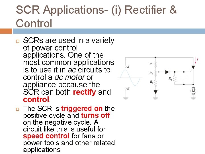
SCR Applications- (i) Rectifier & Control SCRs are used in a variety of power control applications. One of the most common applications is to use it in ac circuits to control a dc motor or appliance because the SCR can both rectify and control. The SCR is triggered on the positive cycle and turns off on the negative cycle. A circuit like this is useful for speed control for fans or power tools and other related applications
SCR Applications- (ii) Crowbar Protection
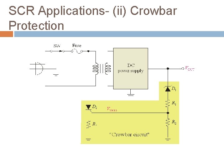
SCR Applications- (ii) Crowbar Protection Another application for SCRs is in crowbar circuits (a crowbar across a voltage source and shorting it out!) The purpose of a crowbar circuit is to shut down a power supply in case of over-voltage. Suppose the output voltage from the d. c. power supply suddenly increases. This causes the zener diode to break down and conduct current. As the current flows through the zener diode, voltage is developed across resistor R 3 which causes the SCR to conduct current. When the SCR conducts, the voltage source is shorted by the SCR. The supply voltage fuse blows out and the load is protected from overvoltage.
MCT thyristor � MOS Controlled Thyristor (MCT) is voltage controlled fully controllable thyristor. � The MCT is similar in operation with GTO thyristor, but it has voltage controlled insulated gate. � It has two MOSFETs in its equivalent circuit. One is responsible for turn-on and the another is responsible for turn-off.
Protection of Semiconductor devices-SCR Semiconductor devices such as SCRs are sensitive to high voltage, over-current, and any form of transients. For satisfactory and reliable operation they are required to be protected against such abnormal operating conditions. There are many abnormal operating conditions existed but we will only focus on two conditions which are: (i) Overcurrent (ii) Overvoltage
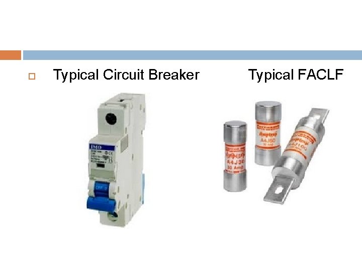
(i) Overcurrent mainly occurs due to different types of faults in the circuit. Due to overcurrent, i 2 R loss will increase and high generation of heat may occurs and exceeded the permissible limit thus burn the device. Overcurrent protection can be provided by connecting a circuit breaker and a fuse in series with the SCR, as usually done for the protection of any circuit. Protective Measure : SCR can be protected from over current by using Circuit Breaker (CB) and fast acting current limiting fuses (FACLF). � CB are used for protection of thyristor against continuous overloads or against surge currents of long duration as a CB has long tripping time. But fast-acting fuses is used for protecting SCR against high surge current of very short duration. �
Typical Circuit Breaker Typical FACLF
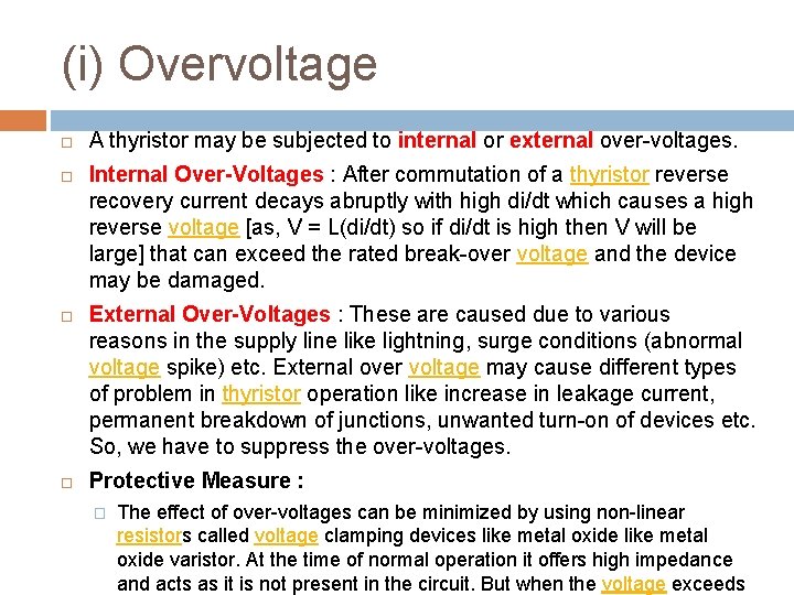
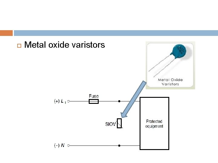
(i) Overvoltage A thyristor may be subjected to internal or external over-voltages. Internal Over-Voltages : After commutation of a thyristor reverse recovery current decays abruptly with high di/dt which causes a high reverse voltage [as, V = L(di/dt) so if di/dt is high then V will be large] that can exceed the rated break-over voltage and the device may be damaged. External Over-Voltages : These are caused due to various reasons in the supply line like lightning, surge conditions (abnormal voltage spike) etc. External over voltage may cause different types of problem in thyristor operation like increase in leakage current, permanent breakdown of junctions, unwanted turn-on of devices etc. So, we have to suppress the over-voltages. Protective Measure : � The effect of over-voltages can be minimized by using non-linear resistors called voltage clamping devices like metal oxide varistor. At the time of normal operation it offers high impedance and acts as it is not present in the circuit. But when the voltage exceeds
Metal oxide varistors
Until then, you should able to master… Characteristics and parameters of a SCR. I-V curve of the SCR together with their regions. What are the Vfb, Vrb, Vbr, Vgt, Ig, Ia, Igt etc. . ? Turning ON and turning OFF of the SCR. Protection offered by the SCR application circuits. Waveforms sketching of the typical SCR circuit (Vin, Vo, Vak, Io). **refer lab session results.