Universiti Malaysia Perlis ENT 356 INSTRUMENTATION SYSTEM Lecture


 Displacement, d = x (t) Velocity, v(t) = dx (t) dt")


 = x 0 sin ωt v (t) = ω x 0")


Capacitive : The basic operation of a capacitive sensor can")
 Inductive: If permeable core is inserted into an inductor, the net inductance is")


 q The linear variable differential transformer (LVDT) is a")


- Slides: 31
Universiti Malaysia Perlis ENT 356 INSTRUMENTATION SYSTEM Lecture 9: Position, Velocity & Acceleration Measurement Sem 2, 2010/2011 1
Outline 1. Introduction 2. Types of Motion o o Rectilinear Angular Vibration Shock 3. Accelerator Principle o o o Types of accelerator Example of accelerator in industry Potentiometer sensor Capacitive and inductive sensor LVDT 4. Level Sensor o o Mechanical Electrical
Introduction q In physics, motion is a change in position of an object with respect to time. Change in action is the result of an unbalanced force. q Motion is typically described in terms of velocity, acceleration, displacement, time and speed. q An object's velocity cannot change unless it is acted upon by a force, as described by Newton's first law. q An object's momentum is directly related to the object's mass and velocity.
q Motion sensors are designed to measure the rate of change of position, location or displacement of an object that is occurring. q If the position of an object as a function of time x(t), then the first derivative gives the speed of object, v(t). If the speed of the object is also changing, then first derivation gives the acceleration. q The primary form of motion sensor is the accelerometer. The device measures the acceleration a(t) of an object. q By integrating a(t) and v(t), it show that the accelerometer can be used to determine acceleration, speed and position of the object as well.
(Unit : m) Displacement, d = x (t) Velocity, v(t) = dx (t) dt Acceleration, a (t) = (Units : m/s) dv (t) dt (Units : m/s 2)
TYPE OF MOTION • Design of a sensor to measure motion is often considered to the type of motion first. • Most common types of motion: - rectilinear - angular - vibration - shock
Rectilinear Motion • This motion is characterized by velocity and acceleration which is composed of straight-line elements. • Objects may accelerate forward, decelerate to stop, reverse and so on. • If the vehicle motion is to be measured, two transducer may be used, one is to measure motion in forward direction and the other one is perpendicular to the forward axis of the vehicle.
Angular Motion • Definitions The motion of a body about a fixed point or fixed axis, as of a planet or pendulum. It is equal to the angle passed over at the point or axis by a line drawn to the body. • Some sensors are designed to measure only rotations about some axis, such as the angular motion of the motor shaft.
Vibration Motion • Vibration refers to mechanical oscillations about an equilibrium point. The oscillations may be periodic such as the motion of a pendulum or random such as the movement of a tire on a gravel road. • More often, vibration is undesirable, wasting energy and creating unwanted sound--noise. For example, the motions of engines, electric motors, or any mechanical device in operation are usually unwanted vibrations. Such vibrations can be caused by imbalances in the rotating parts, uneven friction, the meshing of gear teeth, parts that are dragging together
• For analytical treatments, vibration is defined in term of a regular periodic motion where the position of an object in time is given by: x (t) = x 0 sin ωt Where: x (t) = object position (m) x 0 = peak displacement from equilibrium (m) ω = angular frequency/ speed (rad/s) • If an object rotates, we define the time to complete 1 rotation as a period T, that correspond to a frequency f = 1/T. the frequency then represent no. of revolutions per second = 1 Hz. Then we can see ω and f are related by: ω = 2π f
Equations x (t) = x 0 sin ωt v (t) = ω x 0 cos ωt a (t) = -ω2 x 0 sin ωt Peak Acceleration/ Amplitude
Shock Motion • A special type of acceleration occurs when an object that may be uniform motion or modestly accelerating is suddenly brought to rest. • Such phenomena are the result of very large acceleration, or actually decelerations as when object is dropped from some height onto a hard surface. • Shock motion deceleration that are characterized by very short time.
ACCELEROMETER PRINCIPLES • There are several physical process that can be used to develop a sensor to measure acceleration. • The most design is based on combination of Newton’s law of mass acceleration and Hooke’s law of spring action. • Mostly used principles are: - spring-mass system - natural frequency and damping - vibration effects
Types of Accelerometer • Variety of accelerometer results from different application with requirements of range, natural frequency and damping. • In general, the specification sheets for an accelerometer will give natural frequency, damping coefficient and scale factor that relates the output to an acceleration input. • Most common type of accelerometer: - Potentiometric - LVDT (linear variable displacement transducer) - Variable reluctance (use inductive principle) - Piezoelectric
Examples of applications of displacement, location and position sensors in industry q Location and position of objects on conveyer systems q Orientation of steel plates in a rolling mill q Liquid/solid level measurements q Location and position of work piece in automatic milling operations q Conversion of pressure to a physical displacement that is measured to indicate pressure q In robotics, to sensing the robot position and robot balancing, normally combine with gyro sensor
Potentiometers sensors Basic Principle: The simplest type of displacement sensors involves the action of displacement in moving the wiper of a potentiometer. This device then converts linear or angular motion into a changing resistance that may be converted directly to voltage and/or current signals. The potentiometer-transducer should not be confused with the potentiometer-instrument.
Potentiometer Construction
Capacitive and inductive sensors (a)Capacitive : The basic operation of a capacitive sensor can be seen from the equation of a parallelplate capacitor: K = the dielectric constant = permittivity=8. 85 p. F/m A = plate common area D = plate separation
(b) Inductive: If permeable core is inserted into an inductor, the net inductance is increased. Every new position of the core produces a different inductance.
q Inductive sensors operate under the electrical principle of inductance. Inductance is the phenomenon where a fluctuating current, which by definition has a magnetic component, induces an electromotive force (emf) in a target object. To amplify a device’s inductance effect, a sensor manufacturer twists wire into a tight coil and runs a current through it. q An inductive sensor has four components; The coil, oscillator, detection circuit and output circuit. The oscillator generates a fluctuating magnetic field the shape of a doughnut around the winding of the coil that locates in the device’s sensing face. q When a metal object moves into the inductive proximity sensor’s field of detection, the oscillation magnetically push back, and finally reduce the Inductive sensor’s own oscillation field. The sensor’s detection circuit monitors the oscillator’s strength and triggers an output from the output circuitry when the oscillator becomes reduced to a sufficient level.
Variable-Reluctant sensors Basic principle: The moving core is used to vary the magnetic flux coupling between two or more coils, rather than changing an individual inductance. Most common: Linear variable differential transformer(LVDT)
Linear variable differential transformer (LVDT) q The linear variable differential transformer (LVDT) is a type of electrical transformer used for measuring linear displacement. q The transformer has three solenoidal coils placed end-to-end around a tube. The center coil is the primary, and the two outer coils are the secondaries. A cylindrical ferromagnetic core, attached to the object whose position is to be measured, slides along the axis of the tube.
q The primary winding is excited by a high frequency (5 to 10 k. Hz is typical), low voltage, constant amplitude AC signal. q This induces voltages in the two secondary coils, with the two signals being 180° out of phase because of the opposite winding directions. q If the core is placed at the mid point, the two secondary voltages will be equal in amplitude and will thus cancel leaving no output. q As the core is moved off-center, the secondary voltages will change, with one increasing and the other decreasing, thus leaving a net output. q The output voltage will increase as the core moves further from the mid point. As the core moves through the mid point, the signal decreases to zero and then increases again. q There is a sudden 180° phase change in the output signal with respect to the excitation signal as the core passes the midpoint and this allows one to detect the direction of the displacement of the core.
q The signal conditioning for LVDTs consists primarily of circuits that perform a phase-sensitive detection of the differential secondary voltage. q The output is thus the a dc voltage whose amplitude relates the extent of the displacement, and the polarity indicates the direction of the displacement. q A variety of LVDTs are available with linear ranges at least from ± 25 mm down to ± 1 mm. q The static transfer function is typically given in millivolts per millimeter (m. V/mm) for a given primary amplitude.
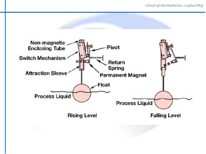
LEVEL SENSORS The measurement of solid or liquid level calls for a special class of displacement The level measured is most commonly associated with material in a tank or hopper.
Level measurement techniques. Mechanical: One of the most common techniques for level measurement, particularly for liquids , is a float that is allowed to ride up and down with level changes. This float is connected by linkages to a secondary displacement measuring system such as a potentiometer device or LVDT core.
Electrical:
EXERCISES 1. A variable dielectric capacitive displacement sensor consists of two square metal plates of side 5 cm, separated by a gap of 1 mm. A sheet of dielectric material 1 mm thick and of the same area as the plates can be slid between them. Given that the dielectric constant of air is 1 and that of the dielectric material 4, calculate the capacitance of the sensor when the input displacement x = 0. 0 , 2. 5 , and 5. 0 cm. 2. An LVDT has a maximum core motion of ± 1. 5 cm with a linearity of ± 0. 3% over that range. The transfer function is 23. 8 m. V/mm. If used to track a work-piece motion from -1. 2 to +1. 4 cm, what is the expected output voltage? What is the uncertainty in position determination due to non-linearity?
Don’t forget to read your supplementary reading notes no. 1
THANK YOU END OF LECTURE 9 Q&A? ?