Universiti Malaysia Perlis ENT 356 INSTRUMENTATION SYSTEM Lecture


- Slides: 50

Universiti Malaysia Perlis ENT 356 INSTRUMENTATION SYSTEM Lecture 4. 1: Signal Conditioning Sem 2, 2010/2011 1

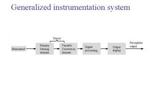
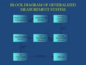
Components of a General Measurement System Input True value Output Sensing element Signal conditioning element School of Mechatronics Engineering Measured value Signal processing element Data presentation element

Components of a General Measurement System School of Mechatronics Engineering Signal conditioning element: Receives the output/SIGNAL from the sensing element then it converts into a more suitable signal for further processing, like a DC Voltage, DC Current or frequency signal. Example: 1) Deflection bridge which converts an impedance change into voltage change 2) Amplifier which converts milivolts to volts 3) Oscillator which converts an impedance change into variable frequency voltage.

Introduction School of Mechatronics Engineering o Signal from detector/sensing stage has to be modified (conditioned) in order to make it more usable. o This signals is then to be use in later stage of system that may consist of processing elements. o Proper selection of signal conditioning circuit can improve the quality and system performance. o Example of signal conditioning can be amplification and filtering. o We’ll discuss analog signal conditioning only. Sem 2, 2010/2011 4

Introduction School of Mechatronics Engineering Amplification q. Increase the level of input signal to better suit further processing. q. Improve the sensitivity and resolution of the measurement. Filtering q Reject useless noise within certain frequency range. q Prevent signal aliasing and distortion. Sem 2, 2010/2011 5

Amplifier School of Mechatronics Engineering o Required in the system to improve the signal strength which is typically in the low level range of less than a few m. V. o In some cases, amplifiers is necessary in providing impedance matching and isolation. o One of the very known important amplifier is the operational amplifiers Sem 2, 2010/2011 6

Operational Amplifier (Op Amp) School of Mechatronics Engineering o An operational amplifier ("op-amp") is a DC-coupled high-gain electronic voltage amplifier with a differential input and, usually, a single-ended output. o An op-amp produces an output voltage that is typically hundreds of thousands times larger than the voltage difference between its input terminals. o Can be used to performs an important functions for signal conditioning and processing like isolation, addition, inversion, multiplication, subtraction and division. o Other mathematical operations can be also perform such as integration and differentiation. Fairchild semiconductor, LM 741 Sem 2, 2010/2011 7

Operational Amplifier (Op Amp) School of Mechatronics Engineering Operational Amplifier Notation and Parameter The circuit symbol for an op-amp is shown, where: V+ VVout Vs+ Vs- : non-inverting input : output : positive power supply : negative power supply Gain, A = Vout/Vin where Vin = V+ - VGain (d. B), Ad. B = 20 log (Vout/Vin) Sem 2, 2010/2011 8

Operational Amplifier (Op Amp) School of Mechatronics Engineering Operational Amplifier Notation and Parameter – Input Parameters Input Offset Voltage that must be applied to one of the input pins in order to give zero output voltage. Input Offset Current Differences of two input bias current when the output voltage is zero. Input Bias Current Average of both current flowing into both of the inputs. Input Resistance of the operational amplifier at either input when the other grounded. Input Voltage Range Voltage that common to both inputs and ground. Sem 2, 2010/2011 9

Sem 2, 2010/2011 10

Operational Amplifier (Op Amp) School of Mechatronics Engineering Operational Amplifier Notation and Parameter – Output Parameters Output Short Circuit Current Maximum output current that the operational amplifier can deliver to the load. Output Voltage Swing Maximum output voltage (peak) that the operational amplifier can give without distortion or clipping. This depends on the load resistance. Output Resistance at the operational amplifier’s output. Sem 2, 2010/2011 11

Sem 2, 2010/2011 12

Operational Amplifier (Op Amp) School of Mechatronics Engineering Operational Amplifier Notation and Parameter – Dynamic Parameters Large Signal Voltage Gain The ratio of the maximum voltage swing to the change in the input voltage required to drive the output from zero to a specified voltage. Slew Rate of change of the output voltage with the operational amplifier having a unity gain. Open-Loop Voltage Gain Output voltage to input voltage ratio of the operational amplifier without feedback. Supply Current that the operational amplifier will draw from the supply. Common Mode Rejection Ratio A quantify of the ability of the operational amplifier to reject signals that are simultaneously present at both inputs Bandwidth Usually specified as unity gain bandwidth. Power Consumption The power consume by the operational amplifiers when operated. 13

14

Operational Amplifier (Op Amp) School of Mechatronics Engineering Ideal Operational Amplifier o Characteristics of ideal operational amplifier can be listed as follows: § Infinite input impedance § Zero output impedance § Infinite open loop gain § Infinite bandwidth, slew rate and CMRR o For ideal operational amplifier the output voltage is zero whenever there is equal voltage is applied to both of its inputs. Sem 2, 2010/2011 15

Operational Amplifier (Op Amp) School of Mechatronics Engineering Type of operational amplifier circuits q q Inverting Amplifier Non-Inverting Amplifier Differential Amplifier Instrumentation Amplifier Sem 2, 2010/2011 16

Operational Amplifier (Op Amp) School of Mechatronics Engineering Inverting Amplifier o R 2 is used to feedback the output to the inverting input, Vin o R 1 is the impedance connected to Vin. o This connection is known as summing point o Sum of current at summing point must be zero; o Thus, Ohm’s law; 17

Operational Amplifier (Op Amp) School of Mechatronics Engineering Inverting Amplifier – Summing amplifier o Modification of the inverting amplifier. o Used as an summing amplifier, that sum two or more input voltages. o The output voltage TF; Sem 2, 2010/2011 18

School of Mechatronics Engineering Signal Conditioning – Inverting Op Amp The most common circuit used for signal conditioning is the inverting amplifier circuit as shown below, this amplifier was first used when op-amps only had one input, the inverting (-) input. The voltage gain of this amplifier is (-R 2/R 1) x Vin . Thus the level of sensor outputs can be matched to the level necessary for the data acquisition system. The input impedance is approximately ∞ and the output impedance is nearly zero. Thus, this circuit provides impedance transformation between the sensor and the data acquisition system. Inverting Amplifier

School of Mechatronics Engineering Signal Conditioning – Inverting Op Amp It is important to remember that the voltage swing of the output of the amplifier is limited by the amplifier's power supply as shown in Figure below, In this example, the power supply is +/- 13 V. When the amplifier output exceeds this level, the output is ``clipped''.

Operational Amplifier (Op Amp) School of Mechatronics Engineering Non Inverting Amplifier o Assume again, voltage at summing point, S is zero; o And from Ohm’s law; o Solving for Vout; 21

School of Mechatronics Engineering Signal Conditioning – Inverting Op Amp Another commonly used amplifier configuration is shown below. The gain of this circuit is given as 1+(R 2/R 1). The input impedance is nearly infinite (limited only by the op-amp's input impedance) and the output impedance is nearly zero. The circuit is ideal for sensors that have a high source impedance and thus would be affected by the current draw of the data acquisition system. Non-Inverting Amplifier

Operational Amplifier (Op Amp) School of Mechatronics Engineering Voltage Follower o Unity gain o High impedance o Vin = Vout o Function: an impedance transformer in the sense of converting a voltage at high impedance to the same voltage at low impedance. Sem 2, 2010/2011 23

Operational Amplifier (Op Amp) School of Mechatronics Engineering Differential Amplifier o The op-amp can also be used to subtract two signals. o This circuit is commonly used to remove unwanted DC offset. o It can also be used to remove differences in the ground potential of the sensor and the ground potential of the data acquisition circuitry (so-called ground loops). o The output of this circuit is; o Where Ad is the differential op amp gain. o Thus V 2 can be the output of the sensor and V 1 can be the signal that is to be removed. Inverting Amplifier 24

Operational Amplifier (Op Amp) School of Mechatronics Engineering CMMR Differential Amplifier o The common-mode input voltage is the average of voltage applied to the two terminals; o The CMMR for of a differential amplifier is defined as the ratio of the differential gain to the common-mode gain; o CMR is the expression of CMMR in d. B; o The larger the d. B number, the better the differential amplifier. Typical values of CMR range from 60 ~ 100 d. B. 25

Operational Amplifier (Op Amp) School of Mechatronics Engineering Instrumentation Amplifier q Dedicated differential amplifier with very high input impedance. q High common mode rejection features make instrumentation amplifier useful in recovering small signals hidden in large common mode offsets and noise. q Instrumentation amplifier is a close loop devices with certain value of gain. q Can be optimised as signal conditioner for low level signals (DC) in high noise environments. 26

Operational Amplifier (Op Amp) School of Mechatronics Engineering Instrumentation Amplifier q Instrumentation amplifier is divided into two stages; § first stage give a very high input impedance to both of input signals and with single resistor gain setting, § second stage is a differential amplifier with the negative feedback, ground connections and output are all taken out. q Input stage consists of two matched operational amplifiers. 27

Operational Amplifier (Op Amp) School of Mechatronics Engineering Instrumentation Amplifier 28

Operational Amplifier (Op Amp) School of Mechatronics Engineering Instrumentation Amplifier FIRST STAGE SECOND STAGE 29

Operational Amplifier (Op Amp) School of Mechatronics Engineering Instrumentation Amplifier First Stage § Both of input signals is applied to the noninverting input terminal of the operational amplifiers. § The operational amplifier are configured as voltage follower which give the instrumentation amplifier a very high input impedance. § Rg is a gain setting resistor in the following formulae for computing vo: § From the equation, the smaller the value of Rg, the larger the output voltage vo. It is clear that Rg can be used in setting the gain of this first stage. 30

Operational Amplifier (Op Amp) School of Mechatronics Engineering Instrumentation Amplifier Second Stage § The second stage of the instrumentation amplifier is a differential amplifier with unity gain. § The full instrumentation amplifier circuit uses three operational amplifiers. § Hence it is called three amplifier configuration. 31

Operational Amplifier (Op Amp) School of Mechatronics Engineering Instrumentation Amplifier Important features of instrumentation amplifier: Ø Differential input capability with high gain common mode rejection. Ø Selectable gain with high gain accuracy and linearity. Ø High stability of gain with low temperature coefficient. Ø Low DC offset and drift errors referred to input. Ø Low output impedance. 32

Operational Amplifier (Op Amp) School of Mechatronics Engineering Op Amp (Example) 1) What kind of amplifier is this? 2) What is the ‘main rule’ of an op amp? 3) Express Vout in terms of Vin, R 1, and R 2. 33

Filter School of Mechatronics Engineering q Filter is the network used to attenuate certain frequencies but allow others without attenuation. q Consist at least one pass band, which is a band of frequencies that the output is approximately equal to input and attenuation band that the output is equal to zero. q Cut-off frequencies is the frequencies that separate the various pass and attenuation bands. q Important characteristic of filter networks is its construction make use of purely reactive elements. q Two types of filter: Passive Filters Active Filters Sem 2, 2010/2011 34

Filter School of Mechatronics Engineering Types of Filters q Passive filters only use passive circuit component such as resistors, capacitors and inductors. q Active filters use active elements like operational amplifiers in addition to passive elements like resistance, capacitance and inductance. q Both of passive and active filters can be classified as follows: a) Low Pass Filter: deliver low frequencies and eliminate high frequencies b) High Pass Filter: send on high frequencies and reject low frequencies c) Band Pass Filter: pass some particular range of frequencies, discard other frequencies outside that band d) Band Stop Filter: stop a range of frequencies and pass all other frequencies 35

Filter School of Mechatronics Engineering Types of Filters 36

Filter School of Mechatronics Engineering Passive Filter - Low Pass Filter o Blocks high frequencies and passes low frequencies. o Ideal LPF: signals above cutoff frequency, fc are simply rejected. o In terms of resistor and capacitor, cut-off frequency, fc is given by: o At low frequencies, the capacitive reactance is very high, therefore the capacitor circuit acts like an open circuit. These condition gives o Gain is given by; o At very high frequencies, the capacitive reactance is very low therefore Vout is very small compared to Vin. 37

Filter School of Mechatronics Engineering Passive Filter - Low Pass Filter (Design Example) A measurement signal has a frequency <1 k. Hz, but there are unwanted noise at about 1 MHz. Design a signal conditioning circuit, by means of LPF that attenuates the noise to 1%. 38

Filter School of Mechatronics Engineering Passive Filter – High Pass Filter o Passes high frequencies and blocks/rejects low frequencies. . o Ideal LPF: signals below cutoff frequency, fc are simply rejected. o In terms of resistor and capacitor, cut-off frequency, fc is given by: o Gain is given by; o At low frequencies, the gain is small, therefore Vout is small compared to Vin. o As the frequencies goes high the gain approaches unity. 39

Filter School of Mechatronics Engineering Passive Filter – High Pass Filter (Design Example) Pulses for a stepping motor are being transmitted at 2000 Hz. Design a filter to reduce 60 Hz noise. 40

Filter School of Mechatronics Engineering Passive Filter – Band Pass Filter o Blocks frequencies below a low limit and above a high limit, while passing frequencies between the limits. o Can be constructed by cascading LPF and HPF. o At frequencies below the pass band, BPF behave like HPF while above the pass band frequencies the BPF acts like LPF. o In pass band, the BPF circuit is almost as a resistive network. o Lower cut-off freq. ; o Upper cut-off freq. ; o Thus, gain is given by; 41

Filter School of Mechatronics Engineering Passive Filter – Band Stop Filter o Blocks a specific range of frequencies. o Cam be realized. but not very affective one, simple RC combination also known as notch filter. o The circuit is called twin-T filter. o Twin T BSF; At the very low and high frequencies the gain is almost unity, but between the two there is a frequency where the gain become zero. o The frequency is known as Notch Frequency, fo. 42

Filter School of Mechatronics Engineering Active Filter o Generally the impedances are used in the inverting amplifiers using operational amplifiers. o Basic relationship can be used to obtain the desired filter sections is as follows (in the case of inverting amplifiers). o The voltage can also be amplified. 43

Filter School of Mechatronics Engineering Active Filter Active filters have three main advantages over passive filters: o Inductors can be avoided. Passive filters without inductors cannot obtain a high Q (low damping), but with them are often large and expensive (at low frequencies), may have significant internal resistance, and may pick up surrounding electromagnetic signals. o The shape of the response, the Q (Quality factor), and the tuned frequency can often be set easily by varying resistors, in some filters one parameter can be adjusted without affecting the others. Variable inductances for low frequency filters are not practical. o The amplifier powering the filter can be used to buffer the filter from the electronic components it drives or is fed from, variations in which could otherwise significantly affect the shape of the frequency response. 44

Filter School of Mechatronics Engineering Active Filter – Low Pass Filter 45

Filter School of Mechatronics Engineering Active Filter – High Pass Filter 46

Filter School of Mechatronics Engineering Active Filter – Low Pass Filter (non-inverting op amp configuration) 47

Filter School of Mechatronics Engineering Active Filter – High Pass Filter (non-inverting op amp configuration) 48

Filter School of Mechatronics Engineering Active Filter – Band Pass Filter 49

School of Mechatronics Engineering End of Lecture 4. Thank You 50
 Perkhidmatan psikiatri di malaysia
 Universiti putra malaysia
 Jam kredit
 Elaun profesor madya ds54
 Universiti teknologi mara akta 173
 Bina ayat universiti
 Tenth thousandth
 Capitulo 7a negative tu commands
 356 dat
 Item 356
 Weerklank 356
 356 in scientific notation
 356 est
 Al 356
 356+25
 356 - 323
 Malaysia malaysia malaysiansleereuters
 01:640:244 lecture notes - lecture 15: plat, idah, farad
 Teknologi tenaga perlis consortium
 Radial circuits
 Peta daerah perlis
 Penanaman di dataran selangor dan dataran hilir perak
 Warisan kerajaan kedah kelantan dan perlis
 Perlis thompson principle
 Kesultanan perlis
 Scr forced commutation
 Man instrument system block diagram
 Primary sensing element
 Draw the block diagram of generalized measurement system
 Generalized instrumentation system
 Maimunah aminuddin
 Uniform building by-laws 1984 (amendments 2012)
 Education system malaysia
 Power system dynamics and stability lecture notes
 Advanced operating system notes
 Power system analysis lecture notes
 Uphcp
Uphcp Lymphatic
 Power system dynamics and stability lecture notes
 Schlosshotel weikersdorf
 Seven core metrics of software project
 Piping and instrumentation diagrams
 Flow meter symbol p&id
 Process control instrumentation technology
 Pen grasp
 Fsr in gas turbine
 Measurement and instrumentation ppt
 Intel pin tool tutorial
 Piping p&id symbols
 Power supply for nim instrumentation
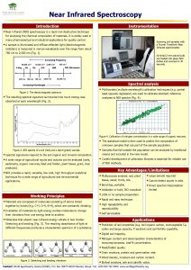
 Near infrared spectroscopy instrumentation


