DESIGNING FOR FIRE SAFETY Selangor Uniform Building amendmentno
(no 2) By-Laws 2012 and Malaysian Standards")
DESIGNING FOR FIRE SAFETY Selangor Uniform Building (amendment)(no 2) By-Laws 2012 and Malaysian Standards MS 1183: 2015 Ar Chong Lee Siong APAM MIFire. E MMIArbs PAM CPD SEMINAR

The Uniform Building By-Laws is a “PRESCRIPTIVE” BUILDING CODE • Compliance with this code is a requirement by law • Sets rules and regulations on the application of the code • Provides pre-determined prescriptions The prescriptions are absolute : no smaller than……. . no bigger than……. . no shorter than…… no longer than…… or no less than and no more than.

The MS 1183: 2015 is a “Descriptive” code of practice • Provides informative descriptions • Establishes normative practices • Describes performance criteria

CONCEPTS OF FIRE SAFETY 1 EVACUATION 2 PASSIVE CONTAINMENT 3 ACTIVE INTERVENTION 4 ACCESS FOR FIRE FIGHTING AND RESCUE Specific prescriptions with reference to Purpose Group and occupancy, type, size and height of building UBBL Schedules 5, 6, 7, 8, 9, 10 Prescriptions with reference to building Height and Volume, for ALL building types.
 I : Small Residential II : Institutional III : Other")
PURPOSE GROUP UBBL (2012) I : Small Residential II : Institutional III : Other Residential V : Shop VII : Place of Assembly IV : Office VI : Factory VIII : Storage and general

MS 1183: 2015 : Occupancy characteristics FAMILIAR AWAKE UNFAMILIAR Office Carpark Warehouse School Cinema Bus station Shop Factory ASLEEP Long term Short term Medical Shopping Complex Hospital outpatient Private house Condominium Hotel Hospital inpatient

• EVACUATION • • • Detection Alarm Exits Travel distance Components Capacity of exits Accepted assumption in designing for safe evacuation: “Only one fire at one location at a time”

Non-Sprinklered

Temperature / size NATURE OF FIRE Flashover Untenable condition Time Stage 1 Ignition & growth Stage 2 development Stage 3 Full fire Stage 4 Decay

ASET Untenable condition Temperature / size Available Safe Egress Time detection alarm movement Total evacuation Time ignition Factor of safety: Required Safe Egress Time RSET < 0. 75 ASET

exit • Final exit • ‘Alternative exits’ • Storey exit • Horizontal exit • Exit route

Final exit • UBBL 133 – interpretations • Final exit refers to the threshold that separates “still within the building” and “out of the building”. The liability of the design for evacuation from the building ends at this point.

‘Alternative exits’ • UBBL 166 • This is the primary concept for safe evacuation. Every floor space shall be provided with at least two exits on the basis that if one exit is inoperable, the other exit can serve the function. • This ‘designing for redundancy’ principle applies to all aspects of evacuation.
 separated")
Horizontal exit • UBBL 171 • Exits that lead to an adjacent (horizontal) separated compartment within the same floor

Storey exit • UBBL 167, 174 • Exits from a floor which is of a different level from the final exit, or, if on the same level, a distance away from the final exit. • A storey exit is to lead to a final exit.

Exit route • UBBL 133 – interpretations • UBBL 169 • the protected passage from a storey exit that leads to the final exit. • Can include spaces that are designated as areas of refuge anywhere between the storey exit and the final exit

storey exit Travel distance Final exit Exit route horizontal exit Final exit

MS 1183: 2015 EVACUATION STRATEGIES TOTAL EVACUATION • Simultaneous • Phased PROGRESSIVE EVACUATION • Vertical or horizontal • Zoned

SIMULTANEOUS EVACUATION storey exit Travel distance Exit route Travel distance horizontal exit Final exit

SIMULTANEOUS EVACUATION storey exit Exit route Final exit

PHASED EVACUATION 3 storey exit topmost floor 4 other floors above 2 1 floor above fire Exit route floor on fire Final exit 5 other floors

PROGRESSIVE EVACUATION: VERTICAL and HORIZONTAL storey exit Exit route REFUGE storey exit Exit route Final exit horizontal exit

ZONED EVACUATION final exit horizontal exit final exit

ZONED EVACUATION final exit horizontal exit final exit
 be approved with")
EVACUATION LIFTS UBBL 2012 34 A “ Any building shall a) be approved with access to enable disabled persons to get into, out of and within the building……. ” c)…. . (to be in). . . compliance with Malaysian Standards MS 1183 and MS 1184: 2014 15. 6 “All lifts in new buildings should comply to statutory requirement on fire requirement for evacuation. ” MS 1183: 2015 Annex G Recommendations for refuges and evacuation lifts

EVACUATION LIFTS A designated Evacuation Lift …. . • Shall be within a Protected Shaft • Shall be a component within a protected Exit Route • Shall be able to switch to evacuation mode by Authorised Person at the Fire Fighting Access Level • Preferably to be a lift in every day use • i. e the physical and functional requirements is similar to a BOMBA lift.

• UBBL 165 • 7 th Schedule • Dead end Travel distance • initial travel distance before a point where an alternative path becomes available • Direct distance • Stipulates that travel distance must be measured along the actual path of travel • Open plan • Where an actual path of travel cannot be determined, the direct distance can be measured as a straight line direct to the exit. Permitted travel distance is then reduced to 2/3.
 Max 15 m if room < 6 pax Final exits To")
UBBL 165 (B) Max 15 m if room < 6 pax Final exits To comply with dead end and travel distance Max distance is 15 m within room plus max allowable travel distance From door of room to final exit Evacuation : multiple areas
 In the case of individual rooms")
165. Measurement of travel distance to exits. (3) In the case of individual rooms which are subject to occupancy of not more than six persons, the travel distance shall be measured from the doors of such rooms: Provided that the travel distance from any point in the room to the room door does not exceed 15 metres. (3) In any of individual room which is subjected to occupancy of not more than six persons, the travel distance shall be measured from the door of such room: Provided that the area of the room does not exceed 15 square metres or any other area determined by the Fire Authority. To clarify that this requirement is applicable to each individual room. Measurement based on floor area of a room provides stricter control.
 Travel distance measured from door if room is less")
Final exits UBBL 165 (B) Travel distance measured from door if room is less than 15 m 2 and with less than 6 occupants Evacuation : multiple areas

Horizontal exits storey exits Evacuation : multiple areas

1 Horizontal exits 23

2 2 1 Horizontal exits

Exit Route components • • • Exit door Exit discharge Protected corridor Protected staircase Balcony approach Single staircase

Exit door, exit discharge • • UBBL 173 UBBL 186 UBBL 193 UBBL 133 - interpretations • ‘Door’ refers to the physical door installed at an exit, and all its functional components e. g. locksets, latches, hinges and closers • ‘discharge’ refers to the ‘doorway’ or threshold of an exit

Exit door, exit discharge • • Not all fire rated doors are exit doors Not all exit doors need to be fire doors Not all doors need to be exit doors Not all doors can be exit doors • To qualify as an Exit Door: • Exit doors must always be able to be opened (without undue effort) at all times • Exit discharge must always allow the passage of people at all times • ‘Exit’ in this context means storey exit, horizontal exit or final exit

Protected corridor, protected staircase • UBBL 133 -interpretations • UBBL 157, 189, 190, 191 • While not expressed, it is inferred from the UBBL that all components that form the Exit Route shall be of protected construction. • Using the same inference, ‘protected’ shall mean ‘enclosed’, ‘separated’ or ‘isolated’ from untenable exposure to Fire or Smoke

Single stair • UBBL 194 • Special provision for the common ‘shop-house’ design • Usage limited to shop (ground floor only), residential or office. • Uppermost floor level limited to 12 m

UBBL 2012 : amended provision for: 194. Buildings with single staircase. A single staircase may be permitted in the following premises: (a)any dwellings at a height of 12 metres measured from the fire appliance access level to the highest and lowest floor; and (a)any shophouses or dwellings not exceeding two (2) storeys or (and) the first storey not exceeding 6 metres from the ground level.
 : single staircase for shop house Single staircase House/ only office")
Clause 194 (b) : single staircase for shop house Single staircase House/ only office <=12 m <= 6 m Shop 1) House only on upper floor 2) No more than 2 storeys 3) Height of first floor no more than 6 m above ground level Clause 166 and 167 (not less than two exits) shall apply for other building types

Capacity of exits • UBBL 7 th Schedule • UBBL 175, 176, 178 • Occupant load • Exit width • Application of horizontal exit

Sample calculation Scenario 1: upper floor assembly area in an institutional building Stair A Stair B 50 m Occupancy load Assume lobby Cper is inaccessible, persons unit for stair 75 = 100 C VII = horizontal exit, persons per= unit (UBBL 180(b)) =1. 35 m 2/pax Therefore and B 4. 95, mustsay accommodate total occupancy 20 m / 75 = = 3. 71, 5 371371 pax /A 1000 m 2 / 1. 35 m 2 = 741 persons 741 stairs 371 mpersons perfor stair 0. 55 m= == 2. 20 2. 75 m width each stair 4. 05/x 2 x 0. 55 m min width lobby C Lobby C

Sample calculation Scenario 2: upper floor assembly area in an institutional building Stair A Stair B 15 m 35 m B = stair. C=inaccessible, 75 pax per unit Assume either B or D 222 persons 260/ = 3. 47 Must 75 accommodate 3. 0 x 0. 55 m = 1. 65 +0. 3 = 1. 95 width 20 m 519 persons 519 / 2 exits = 260 persons D = horizontal exit = 100 pax per unit 260/ 100 = 2. 6 3. 0 x 0. 55 m = 1. 60 m width door D Lobby C

storey exit 250 pax Final exit 400 pax 150 pax 200 pax 250 pax 400 pax Exit route 400 pax horizontal exit 300 pax 200 pax 400 pax Final exit 400 pax

PROGRESSIVE EVACUATION: VERTICAL and HORIZONTAL 200 pax storey exit Exit route 200 pax REFUGE 200 pax storey exit 1000 pax 200 pax Exit route 200 pax Final exit 1000 pax 200 pax horizontal exit

ZONED EVACUATION final exit 400 pax horizontal exit 200 pax final exit 200 pax

UBBL 2012 : 7 th Schedule : Maximum Travel Distance 9 6 10 10 0 60 30 45 45 30 60 45 45 22. 5 0 NR NR 61 NR 22. 5 30 22. 5 NR 30 45 22. 5 UBBL 1984 provisions shown in RED

UBBL 2012: 7 th Schedule : Occupant Load and capacity of exits 22 15 100 60 50 ------OFFICE ------SHOP 50 60 60 50 45 50 30 UBBL 1984 provisions shown in RED

Compartmentation • Size limitations of ‘compartments’ • Fire Resistance Ratings of ‘elements of structure’

Compartmentation To contain the spread of fire from point of origin To limit the potential size of the fire To separate areas of different levels of hazard To separate areas for safe exit, evacuation or refuge To limit threat to the structural integrity of the building • To allow sufficient time for safe evacuation, active extinguishment of fire and rescue. • • •

0. 33 2. 20 3. 46 4. 39 5. 30
 • Combustion")
compartmentation Fire Load • Surface area / volume of combustible content (A) • Combustion heat per area / volume (B) • Fire Load = (A) x (B)

Temperature / size NATURE OF FIRE Flashover Untenable condition Time Stage 1 Ignition & growth Stage 2 development Stage 3 Full fire Stage 4 Decay

Temperature / size EQUAL VOLUME ‘high’ Btu ‘moderate’ Btu ‘low’ Btu Time

Temperature / size EQUAL Btu ‘high’ volume ‘moderate’ volume ‘low’ volume Time

‘high’ Btu ‘moderate’ Btu ‘low’ Btu EQUAL Btu Temperature / size EQUAL VOLUME ‘high’ volume ‘moderate’ volume ‘low’ volume Time Purpose Group classification Limitation of Floor Areas and Volume Prescription of Fire Resistance Rating

Grenfell

Accepted assumption in designing for safe evacuation: “Only one fire at one location at a time” Primary objective of compartmentation: “To contain the one fire within the one location at all times”

Contributing factors to potential fire load : Contents of the building • • Fittings and furnishings………. . ……………. . including the building itself Furniture and equipment Consumables Storage items Presence of hazardous materials Presence (or absence) of human occupants

These factors lead to the designation of purpose groups in the 5 th Schedule, UBBL, ……. ……and to the prescriptions of UBBL 6 th Schedule th 8 Schedule th 9 Schedule

UBBL 5 th Schedule • UBBL 5 th schedule • UBBL 134 • UBBL 135, 136, 137, 138, 139 • Every building is to have one overall designation • Individual components of building with different usage from overall must be designed to accommodate the more stringent requirement, and where these requirements ‘spill’ into the other parts of the building, the more stringent requirement applies. • Only ‘horizontal’ separation is allowed between buildings of different purpose groups

UBBL 5 th Schedule • Dimensions of buildings and compartments • Single storey buildings : limitations apply only to II and III • Others : dimensional limitations does not apply to I, IV and VII

other limitations that may affect areas and volumes • UBBL • 136, 220 : if automatic sprinklers installed, limits can be doubled ( x 2 ) • 137 : floor to floor compartmentation • 138 : floor and wall compartmentation for flats, basement and areas of different usage • 139 : compartmentation of hazardous areas

other limitations that may affect areas and volumes • 158, 178 to 188 : specific coverage for VII – places of assembly • Travel distances and occupant loads

UBBL 6 th Schedule • UBBL 142, 145 Construction and protection of external walls

UBBL 8 th Schedule • UBBL 204 to 207 • Flame spread over surfaces of walls and ceilings

UBBL 9 th Schedule • Minimum periods of Fire Resistance for Elements of Structure. • UBBL 213 : every element of structure to have FRP no less than as specified in 9 th Schedule

Elements of structure for application of FRP • Structural frame, beams and columns (excluding roof structures) • Floor (except the lowest floor) • Compartment floor • External wall • Separating wall ( including party wall ) • Compartment wall • Protected shaft : structure and enclosure • Load bearing wall • gallery

UBBL 2012 : SEPARATING WALL : TERRACE HOUSES • Constructional function : Party Wall UBBL 86 • Fire safety function : Separating wall to be Compartment Wall UBBL 138(c) • Check compartment size • Check Fire Resistance Period of elements of structure • UBBL 214 : External Wall and Separating Wall minimum FRP
 All party walls shall generally be")
UBBL 1984 UBBL 2012 86 Party walls. (1) All party walls shall generally be of not less than 200 millimetres total thickness of solid masonry or insitu concrete which may be made up of two separate skins each of not less than 100 millimetres thickness if consctructed at different times: Provided that in multi-storeyed flats and terrace houses of reinforced concrete or of protected steel framed construction having floors and roofs constructed to the requirements of these By-laws, the party wall thereof shall not be less than 100 millimetres total thickness. (2) Party walls in single storeyed houses may be in load-bearing 100 millimetres solid masonry or insitu concrete provided the requirements of Part V, VI and VII of these By-laws are complied with. (3) All party walls shall be carried above the upper surface of the roof to a distance of not less than 230 millimetres at right angles to such upper surface. (4) Other non-combustible materials may be used for party walls provided the requirements of Part V, VI and VII of these By-laws are complied with. -Deleted- By-law 141: Separating walls has already provided the necessary fire requirements served to prevent the spread of fire from one separate unit of house to another. As such the Fire Authority will only make reference to by-law 141.
 : floor and walls separating")
COMPARTMENTS, ELEMENTS OF STRUCTURE AND FRP Service apts 138(c) : floor and walls separating purpose group 215(1) : reference to elements of structure, by building, or by compartments 215(2) : reference to height, by building only 138(d) : floor separating basements Offices 137 : floor to floor compartment for buildings > 30 m height 138(b) : floor and walls separating flats Cineplex Shops Carpark

COMPARTMENTS, ELEMENTS OF STRUCTURE AND FRP Basement compartment volume limit 42, 000 m 3 Separation of vertical ‘shaft’ Compartment D Compartment A Compartment B Compartment C

relevant boundary Reference plane UBBL 6 th SCHEDULE Reference plane

notional boundary Reference plane UBBL 6 th SCHEDULE Reference plane SEPARATING WALL
 Establish Purpose Group 3 h x")
Sample calculation 2 h x 3 w 1) Establish Purpose Group 3 h x 9 w 2) Establish height and width of enclosing rectangle 9 m 1) Enclosing rectangle on reference plane : 24 m high x 9 m wide = 216 m 2 2) Total unprotected area : ( 2 m x 3 m) x 10 = 60 m 2 3 m x 9 m = 27 m 2 total = 87 m 2 3) Percentage of unprotected area : 24 m 87 m 2 / 216 m 2 = 40 % 4) Minimum distance from reference plane to relevant boundary : 5 m (IV –Office) Office building Protected staircase


FLAME TRAJECTORY OUTSIDE WALL OPENINGS Shape of opening Square height 1: 2 1: 3 Distance from face of wall

EXTERNAL WALL BARRIERS UBBL 149 900 mm vertical or 750 mm horizontal barrier

ATRIUMS UBBL 2012 clause 137 UBBL 2012 clause 252 A MS 1183: 2015 Annex B

COMPARTMENTS, ELEMENTS OF STRUCTURE AND FRP Atrium Space

UBBL 1984 137 UBBL 2012 Floor in building exceeding 30 metres in height to be constructed as compartment floor. In any building which exceeds 30 metres in height, any floor which is more than 9 metres above ground floor level which separates one storey from another storey, other than a floor which is either within a maisonette or a mezzanine floor shall be constructed as a compartment floor. -None- Compartmentation by height. (1) In any building not exceeding 30 metres in height, any floor which is more than 9 metres above ground floor level which separates one storey from another storey, other than a floor which is either within a maisonette or a mezzanine floor shall be constructed as a compartment floor. (2) In any building exceeding 30 metres in height, all floors shall be constructed as compartment floors, other than a compartment which is within a residential maisonette which may comprise two storey levels. (3) An atrium shall comply with the requirements of by-law 252 A. To provide stricter requirements in relation to the extent of subdivision of a building as compartment floors.

UBBL 1984 Clause 137 : Compartment Floor In any building which exceeds 30 metres in height, any floor which is more than 9 metres above ground floor level which separates one storey from another storey, other than a floor which is either within a maisonette or a mezzanine floor shall be constructed as a compartment floor.

1984 UBBL cl 137 All Buildings above 30 m All floors above 9 m to be Compartment Floors 9 m or below need not be compartmented

1984 UBBL cl 137 30 m By inference, Buildings below 30 m………. need not have compartmented floors 9 m
 In any building not exceeding 30")
2012 UBBL Clause 137 : Compartment Floor (1) In any building not exceeding 30 metres in height, any floor which is more than 9 metres above ground floor level which separates one storey from another storey, other than a floor which is either within a maisonette or a mezzanine floor shall be constructed as a compartment floor. (2) In any building exceeding 30 metres in height, all floors shall be constructed as compartment floors, other than a compartment which is within a residential maisonette which may comprise two storey levels.

2012 UBBL cl 137 Any building NOT exceeding 30 m All floors above 9 m to be Compartment Floors 9 m or below need not be compartmented

2012 UBBL cl 137 Any building exceeding 30 m All floors to be Compartmented 9 m Including floors below 9 m

2012 UBBL cl 137 30 m Openings between floors shall be designed as an ATRIUM An atrium shall comply with the requirements of by-law 252 A. 9 m

2012 UBBL 252 A Atriums in buildings 1. Minimum dimensions: 6 m and 95 m 2 2. Exits separated from atrium 3. 1 hour FRP separation 4. Automatic sprinklers 5. Smoke control/exhaust system
 • Minimum dimension of")
COMPARTMENTS, ELEMENTS OF STRUCTURE AND FRP Atrium Space (NFPA 101) • Minimum dimension of 6 m and minimum area of 95 m • Required exits to be separated from atrium volume • Atrium construction and usage to be of hazard level no higher than ‘ordinary’ • Entire building to have automatic sprinklers • Designed for smoke exhaust and smoke control • Atrium volume to be separated from adjacent occupancy, or to be engineered such that the adjacent occupancies are not at risk from a fire originating from the atrium

COMPARTMENTS, ELEMENTS OF STRUCTURE AND FRP Atrium Space UBBL 251 Smoke venting for Safe exit

COMPARTMENTS, ELEMENTS OF STRUCTURE AND FRP Atrium Space UBBL 251 Smoke venting for Safe exit

Compartmentation of large volumes

Compartmentation of large volumes

Protection of penetrations through compartments and elements • UBBL 141 : Separating walls • Diameter of combustible pipe < 25 mm • Diameter of non-combustible pipe <150 mm • No flue pipes allowed • Doors to have equal or greater FRP as with the element UBBL 148 : Compartment floor and walls • Opening for protected shaft • Ventilation duct with fire damper • Encased ducts to have FRP no less than half of the element

Protection of penetrations through compartments and elements UBBL 150 : Protected Shafts • for pipes, ducts, sanitary facilities, staircase, lift UBBL 156 : Ventilating Duct in Protected Shaft • To have automatic Fire Dampers at ‘appropriate’ intervals
 Required FRP Max 150 mm (/) Half of required FRP")
Max 25 mm (/) Required FRP Max 150 mm (/) Half of required FRP Required FRP

Half of required FRP Required FRP

Full FRP for structures Half of required FRP


Active systems for…. . • EVACUATION and FIRST AID – Detection and Alarm – Communication – Smoke control – Portable fire extinguishers

ASET Untenable condition Temperature / size Available Safe Egress Time detection alarm ACTIVE CONTAINMENT and EXTINQUISHMENT movement Total evacuation Time ignition Factor of safety: Required Safe Egress Time RSET < 0. 75 ASET

Sprinklered

UBBL 2012 amended 10 th Schedule

UBBL 2012 amended 10 th Schedule A. Hose Reel System B. Sprinkler System C. Gaseous Extinquishing System D. Pressurized Fire Hydrant 1. 2. 3. 4. 5. Manual Electric Fire Alarm Automatic Fire Detector System Centralised Monitoring System Public Address System Fire Command Center

A. Hose Reel System B. Sprinkler System C. Gaseous Extinquishing System D. Pressurized Fire Hydrant 1. 2. 3. 4. 5. Manual Electric Fire Alarm Automatic Fire Detector System Centralised Monitoring System Public Address System Fire Command Center

A. Hose Reel System B. Sprinkler System C. Gaseous Extinquishing System D. Pressurized Fire Hydrant 1. 2. 3. 4. 5. Manual Electric Fire Alarm Automatic Fire Detector System Centralised Monitoring System Public Address System Fire Command Center

A. Hose Reel System B. Sprinkler System C. Gaseous Extinquishing System D. Pressurized Fire Hydrant 1. 2. 3. 4. 5. Manual Electric Fire Alarm Automatic Fire Detector System Centralised Monitoring System Public Address System Fire Command Center

A. Hose Reel System B. Sprinkler System C. Gaseous Extinquishing System D. Pressurized Fire Hydrant 1. 2. 3. 4. 5. Manual Electric Fire Alarm Automatic Fire Detector System Centralised Monitoring System Public Address System Fire Command Center

A. Hose Reel System B. Sprinkler System C. Gaseous Extinquishing System D. Pressurized Fire Hydrant 1. 2. 3. 4. 5. Manual Electric Fire Alarm Automatic Fire Detector System Centralised Monitoring System Public Address System Fire Command Center

A. Hose Reel System B. Sprinkler System C. Gaseous Extinquishing System D. Pressurized Fire Hydrant 1. 2. 3. 4. 5. Manual Electric Fire Alarm Automatic Fire Detector System Centralised Monitoring System Public Address System Fire Command Center

A. Hose Reel System B. Sprinkler System C. Gaseous Extinquishing System D. Pressurized Fire Hydrant 1. 2. 3. 4. 5. Manual Electric Fire Alarm Automatic Fire Detector System Centralised Monitoring System Public Address System Fire Command Center

A. Hose Reel System B. Sprinkler System C. Gaseous Extinquishing System D. Pressurized Fire Hydrant 1. 2. 3. 4. 5. Manual Electric Fire Alarm Automatic Fire Detector System Centralised Monitoring System Public Address System Fire Command Center

OPEN STRUCTURES OPEN CORRIDORS UBBL 2012 10 th Schedule
Total surface area of openings is to be no less than 40%")
OPEN STRUCTURE (1)Total surface area of openings is to be no less than 40% of the total perimeter wall area enclosing the floor or compartment (2)The opening is to be shaped and located in such a way that total length in plan of the opening(s) is to be no less than 50% of the perimeter of the floor or compartment “ Openings” is to be opened to outside, unenclosed space or permitted airwells. Any individual opening having a surface area less than 600 mm 2 or area width of opening is less than 25 mm is not to be regarded as an opening for this purpose.
 x 2 = 150")
Example: Total perimeter length (25 m + 50 m ) x 2 = 150 m minimum 50% = 75 m Total perimeter wall area 150 m x 5 m = 750 m 2 minimum 40% = 300 m 2 OPEN STRUCTURES 5 m 50 m 25 m 75 m Total length of openings (25 m : 50 m + 50 m)x 2 + 50 m = 100 m 150 m 75 mx x 2 m Total area of openings : 150 m : 100 m x 4 m 3 m ==300 m 2
Total surface area of opening(s) is to be no less than 25%")
OPEN CORRIDOR (1)Total surface area of opening(s) is to be no less than 25% of the total perimeter wall area enclosing the balcony (corridor) (2)The opening(s) is to be shaped and located in such a way that total length in plan of the opening(s) is to be no less than 50% of the perimeter of the floor or compartment “ Openings” is to be opened to outside, unenclosed space or permitted airwells. Any individual opening having a surface area less than 600 mm 2 or area width of opening is less than 25 mm is not to be regarded as an opening for this purpose.
 Total perimeter length (24 m + 2 m")
OPEN CORRIDOR 6 m Example (corridor) Total perimeter length (24 m + 2 m ) x 2 = 52 m minimum 50% = 26 m Total perimeter wall area 52 m x 3 m = 156 m 2 minimum 25% = 39 m 2 6 m 6 m 6 m 3 m 2 m 3 m Permitted Airwells (UBBL 40) Total length of openings 24 m + 2 m= 28 m Total area of openings : 28 m x 1. 5 m = 42 m 2

10 th SCHEDULE A : HR B : Spkr C : Gas. Ex D : Pr. Hy 1 : Man. Al 2 : Auto. D 3 : CMS 4 : PAS 5 : FCC

10 th SCHEDULE A : HR B : Spkr C : Gas. Ex D : Pr. Hy 1 : Man. Al 2 : Auto. D 3 : CMS 4 : PAS 5 : FCC

10 th SCHEDULE A : HR B : Spkr C : Gas. Ex D : Pr. Hy 1 : Man. Al 2 : Auto. D 3 : CMS 4 : PAS 5 : FCC

10 th SCHEDULE HOTELS A : HR B : Spkr C : Gas. Ex D : Pr. Hy 1 : Man. Al 2 : Auto. D 3 : CMS 4 : PAS 5 : FCC

10 th SCHEDULE A : HR B : Spkr C : Gas. Ex D : Pr. Hy 1 : Man. Al 2 : Auto. D 3 : CMS 4 : PAS 5 : FCC

SMOKE CONTROL UBBL 2012 251 “smoke control systems where specified shall be designed and installed in accordance with MS 1780: 2017 8 Applications 8. 1 Basement smoke control system 8. 1. 1 Smoke vents (are permitted) for areas below 1, 000 m 2 8. 1. 2 Smoke control systems for areas exceeding 1, 000 m 2 8. 2 Smoke control systems for above ground premises 8. 2. 1 Smoke control systems for areas exceeding 1, 000 m 2 or volume exceeding 7, 000 m 3

MS 1780: 2017 8. 5 smoke control of hotel guestroom corridors 8. 5. 1 “Where internal guestroom corridors are NOT mechanically presurised, such corridors shall be smoke purged or diluted at a rate no less than 10 air change per hour. ” 8. 5. 3 Natural ventilation is permissible only if induced cross ventilation is available……. . ”

Protection of stairs and lobbies UBBL • 196, 197 - smoke lobbies, protected lobbies • 198, 199, 200, 201 – ventilation of stairs • 229 – fire fighting lobbies

Protection of stairs and lobbies • Protected Lobby : protected lobby separated or isolated from fire and smoke infiltration • Smoke Lobby : a protected lobby primarily to isolate staircases from smoke infiltration • ventilated lobby : protected/smoke lobby by means of natural ventilation from outside • Fire Fighting Access Lobby : a protected lobby designed for fire fighting access

Ventilation opening External wall No protected lobby required Protected lobby requirement for building > 18 m (By-Law 197) Protected lobby requirement Building more than 18 m above ground level

Ventilated opening Omission of protected lobby for pressurised staircase for buildings below 45 m Staircase pressurised No protected lobby required For building above 18 m but below 45 m
![Ventilation opening Protected lobby requirement for building > 45 m [By-Law 197(2)] No protected](http://slidetodoc.com/presentation_image_h2/4a042fa60c63b27c106613e295987b48/image-135.jpg "Ventilation opening Protected lobby requirement for building > 45 m [By-Law 197(2)] No protected")
Ventilation opening Protected lobby requirement for building > 45 m [By-Law 197(2)] No protected lobby required Protected lobby to be pressurised Above 18 m, need PROTECTION Above 45 m, protection by PRESSURISATION

FIRE FIGHTING ACCESS UBBL clause 140 UBBL clause 197 A UBBL 197 B

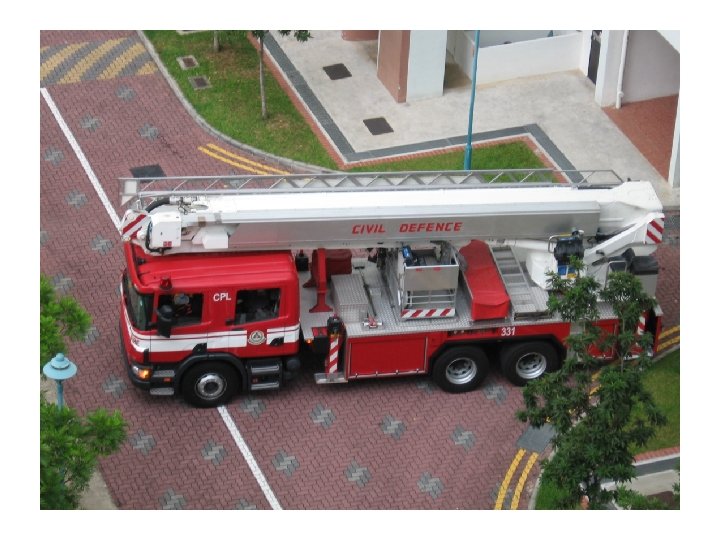
Paris ladder rescue

BOMBA johor factory fire

140 Fire Appliance Access

197 A. Means of access and fire fighting in building over 18. 0 metres high. (1) Buildings in which the topmost floor is more than 18. 0 metres above fire appliance access level shall be provided with means of gaining access and fighting fire from within the building consisting of fire fighting access lobbies, fire fighting staircases, fire lifts and dry or wet rising systems. 197 B. Fire fighting access lobbies shall conform to the following requirements: (a) each lobby shall have a floor area of not less than 6. 0 square metres; and (b) the openable area of windows or area of permanent ventilation shall be not less than 25% of the floor area of the lobby and, if ventilation is by means of openable windows, additional permanent ventilation having a free opening of 464 square centimetres shall be provided except that mechanical pressurisation may be provided as an alternative

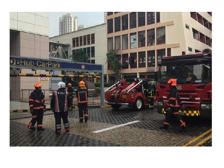
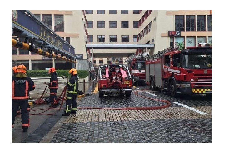
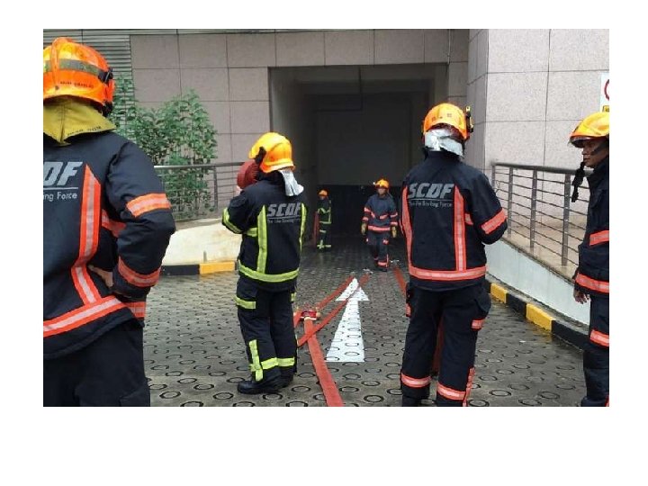
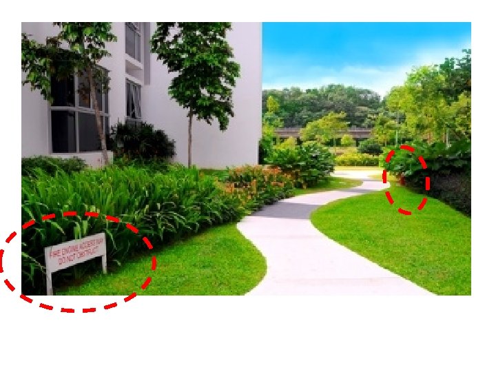
FIRE APPLIANCE ACCESS 2012 UBBL 140 ACCESS WAY An area for the entry, maneuvering and parking of Fire Appliances during fire fighting and rescue operations ACCESS ROAD A road capable of accommodating the passage of Fire Appliances to enter an Access Way ACCESS OPENINGS Doorways or openings that allows fast and safe entry of Fire Fighting and Rescue personnel into a building during fire fighting and rescue operations

EXTERNAL ACCESS Access for emergency and rescue vehicles, equipment and personnel • Roads • Pavements • Parking Availability of water : • Hydrants • Storage tanks • Lakes, rivers, ponds And access to fire fighting systems in the premises

AT THE PREMISES Clarity of : • Type of building and function • Configuration of building • Location of fire control panel • Location of breaching inlets and pump rooms Access into the building • Protected passage • Protected stairs • Firemen’s lift • Fire fighting lobby

Pressurised Hydrant System

Sprinkler System

Dry Riser system

Wet Riser System

External source of water • Hydrants • Lakes, Ponds, Pools, rivers • Fire Tenders Fire Fighting Appliance on ‘Access Way’ Breaching Inlet • Sprinklers • Risers Internal Systems • Sprinklers • Hose reels • Risers

Required portion of building fronting the Access Way ACCESS WAY ACCESS ROAD • minimum width 4. 5 m (suggested) • Gradient <= 1: 8. 3 • Minimum overhead clearance 4. 5 m ACCESS OPENING • Located fronting Access Way • (suggested) width >= required exit width Required portion of building fronting the Access Way ACCESS WAY • Minimum 6 m width • 30 tonnes load • Gradient <= 1: 15 • No overhead obstructions ACCESS ROAD • minimum width 4. 5 m (suggested) • Gradient <= 1: 8. 3 Edge of Access Way • Minimum 2 m overhead • Maximum 10 m clearance 4. 5 m

Maximum 90 m Hydrant to Hydrant Fire Fighting Shaft Fire Fighting Access Lobbies Firemen’s Lift Fire Fighting Staircase Risers (fire mains) Hydrant Emergency Power Generators Fire Pumps Breeching Inlets BA M BO AN A R U TE LAL N JE KAN N A G LU SON A L KO Maximum 30 m Hydrant to Breeching Inlet

FIRE FIGHTING SHAFTS 18 m Fire Fighting Shaft Fire Appliance Access Level Protected stair 9 m

Final exit Evacuation : separation of routes
 All parts of")
FIRE FIGHTING SHAFTS : LOCATION Radial distance Risers (UBBL 230, 231) All parts of floor within 45 m from a landing valve Fire Fighting Access Lobbies (UBBL 197 A) Level distance from furthermost point does not exceed 45 m Route distance Fire Lifts (UBBL 197 A) Not more than 61 m travel distance from furthermost point Fire Fighting Shafts (MS 1183 21. 2. 3) With Fire Lift, no more than 61 m from fire mains outlet measured on route in laying a hose AND Without Fire Lift, no more than 45 m from fire mains outlet measured on route in laying a hose

FIRE FIGHTING SHAFTS : LOCATION check with RADIAL DISTANCE Fire Fighting Access Lobbies Level distance from furthermost point does not exceed 45 m FL F L Risers All parts of floor within 45 m from a landing valve WR W R

FIRE FIGHTING SHAFTS : LOCATION check with ROUTE DISTANCE START Is FIRE LIFT within 61 m ? NO Add Fire Fighting Access Lobby YES Is FIRE MAINS within 61 m ? NO install FIRE MAINS in secondary protected stair within 45 m YES FINISH

FIRE APPLIANCE ACCESS : to Breeching Inlets Min 6 m 2 m to 10 m Accessway Near edge H ax 30 m BI m 8 x 1 Ma BOMBA M Accommodation

FIRE APPLIANCE ACCESS : to Access Openings Min 6 m 2 m to 10 m Accessway Near edge BOMBA H Accommodation WR Max 45 m Protected Access lobby or opening corridor FFAL

FIRE APPLIANCE ACCESS to Access Openings without Fire Mains Min 6 m 2 m to 10 m Accessway Near edge H Max 30 m Access opening Accommodation ce n m 40 ista x d Ma ect dir m 8 1 x BOMBA Ma Max 60 m Route distance

THANK YOU Ar Chong Lee Siong APAM MIFire. E MMIArbs
- Slides: 167