LTEEPC Solutions Overview For SCTE in Oklahoma City

- Slides: 59
LTE/EPC Solutions Overview For SCTE in Oklahoma City and Tulsa, OK July 27 th & 28 th, 2011 By Si Nguyen Director, Wireless Marketing and Product Management snguyen@huawei. com
Contents 1 Market Drivers and Background (30 min) 2 LTE Technology Overview (75 min) 3 LTE Advanced Overview (30 min) 4 LTE Deployment Landscape (15 min) Page 2
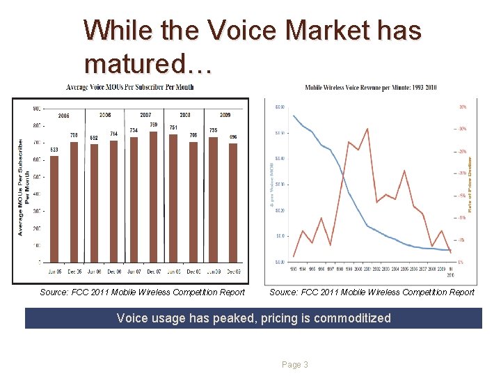
While the Voice Market has matured… Source: FCC 2011 Mobile Wireless Competition Report Voice usage has peaked, pricing is commoditized Page 3
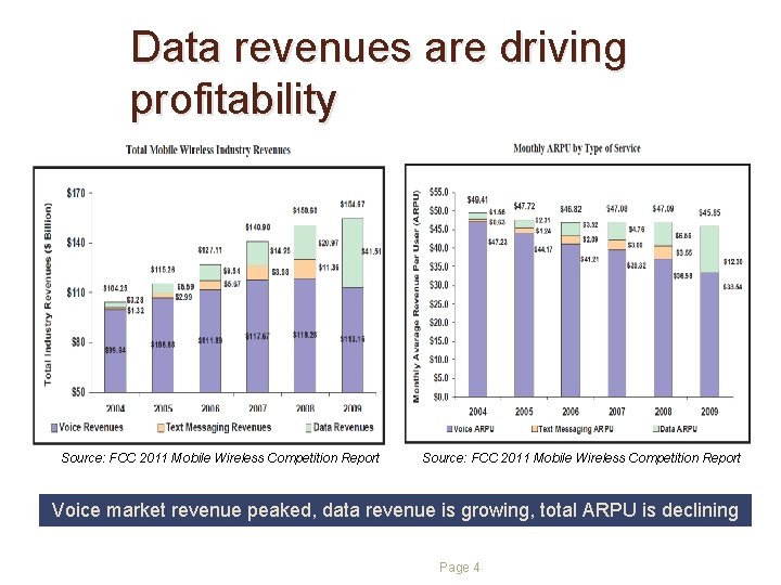
Data revenues are driving profitability Source: FCC 2011 Mobile Wireless Competition Report Voice market revenue peaked, data revenue is growing, total ARPU is declining Page 4
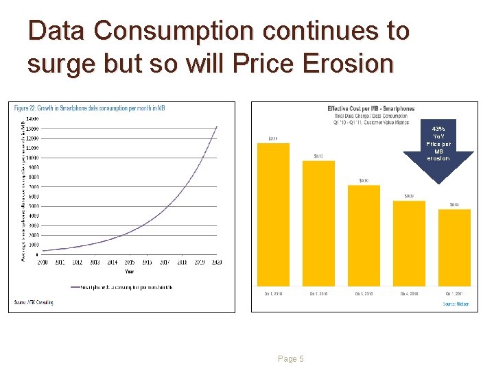
Data Consumption continues to surge but so will Price Erosion 43% Yo. Y Price per MB erosion Page 5
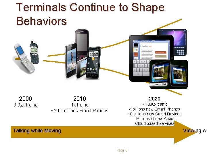
Terminals Continue to Shape Behaviors 2000 2010 0. 02 x traffic 1 x traffic ~500 millions Smart Phones 2020 ~ 1000 x traffic 4 billions new Smart Phones 10 billions new Smart Devices Millions of new Apps Cloud based Services Talking while Moving Viewing wh Page 6
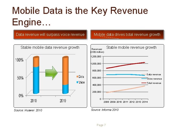
Mobile Data is the Key Revenue Engine… Data revenue will surpass voice revenue Stable mobile data revenue growth Mobile data drives total revenue growth Revenues (US$ million) Stable mobile revenue growth 1, 200, 000 1, 000 800, 000 Data revenue 600, 000 Voice revenue Total revenue 400, 000 200, 000 0 2008 2009 2010 2011 2012 2013 2014 Source: Huawei 2010 Source: Informa 2010 Page 7
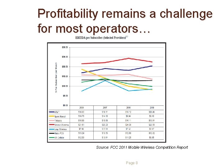
Profitability remains a challenge for most operators… Source: FCC 2011 Mobile Wireless Competition Report Page 8
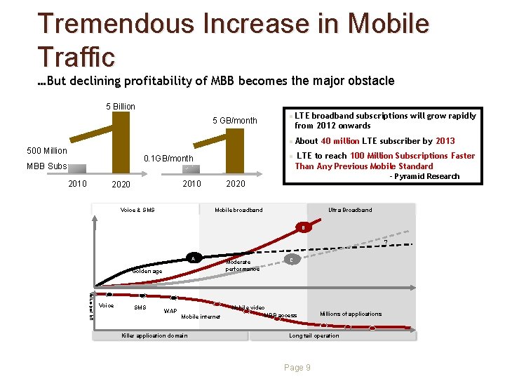
Tremendous Increase in Mobile Traffic …But declining profitability of MBB becomes the major obstacle 5 Billion 5 GB/month l l 500 Million 0. 1 GB/month MBB Subs 2010 l 2010 2020 Voice & SMS 2020 LTE broadband subscriptions will grow rapidly from 2012 onwards About 40 million LTE subscriber by 2013 LTE to reach 100 Million Subscriptions Faster Than Any Previous Mobile Standard - Pyramid Research Mobile broadband Ultra Broadband B ? A Golden age Value per bit Voice SMS WAP Mobile internet Killer application domain Moderate performance C Mobile video MBB access Millions of applications Long tail operation Page 9
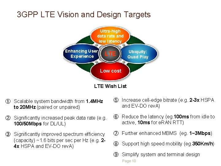
3 GPP LTE Vision and Design Targets Ultra-high data rate and low latency Enhancing User Experience Ubiquity: Quad Play LTE Low cost LTE Wish List ① Scalable system bandwidth from 1. 4 MHz to 20 MHz (paired or unpaired) ⑤ Increase cell-edge bitrate (e. g. 2 -3 x HSPA and EV-DO rev. A) ② Significantly increased peak data rate (e. g. 100/50 Mbps for DL/UL) ⑥ Reduce the latency (eg. 100 ms from idle to active, 10 ms for e. RAN RTT) ③ Significantly improved spectrum efficiency (capacity) ~1. 6 bits per sec per Hz (e. g. 24 x HSPA and EV-DO rev. A) ⑦ Further enhanced MBMS (eg. 1~3 Mbps) ⑧ Support high speed mobility (eg. 350 Km/h) ⑨ Simplify system and terminal design Page 10
Contents 1 Market Drivers and Background (30 min) 2 LTE Technology Overview (75 min) 3 LTE Advanced Overview (30 min) 4 LTE Deployment Landscape (15 min) Page 11
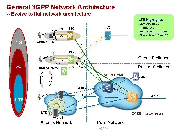
General 3 GPP Network Architecture -- Evolve to flat network architecture LTE Highlights: BSS 2 G BTS GPRS/EDGE -Only Data, No CS -No RNC/BSC -ENode. B interconnected -Differentiated UP and CP MSC BSC Abis Gb RNC 3 G Node. B UMTS/HSDPA Circuit Switched Iu- Iub Iu r Iu -P S PS -U Packet Switched -C SGSN + MME S 6 S 1 -MME HSS Gn / S 11 S 1 -U Gi / SGi LTE GGSN + SGW+PGW e. Node. B Access Network Core Network Page 12
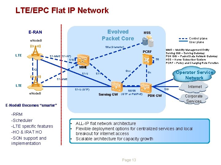
LTE/EPC Flat IP Network Evolved Packet Core E-RAN e. Node. B HSS Control plane User plane S 6 a (Diameter) PCRF LTE S 1 -MME (S 1 -AP) S 10 S 9 MME – Mobility Management Entity Serving GW – Serving Gateway PDN GW – Packet Data Network Gateway HSS – Home Subscriber System PCRF – Policy and Charging Rule Function MME X 2 S 1 -U S 11 Gxc Operator Service Network Gx S 1 -MME LTE S 1 -U (GTP) e. Node. B Serving GW S 5/S 8 (GTP or PMIPv 6) E-Node. B Becomes “smarter” -RRM -Scheduler -LTE specific features -HO & IRAT HO -SON support and implementation SGi PDN GW Internet Corporate Services • ALL-IP flat network architecture • Flexible deployment options for centralized services and local breakout for internet access • Scalable architecture for capacity growth Page 13
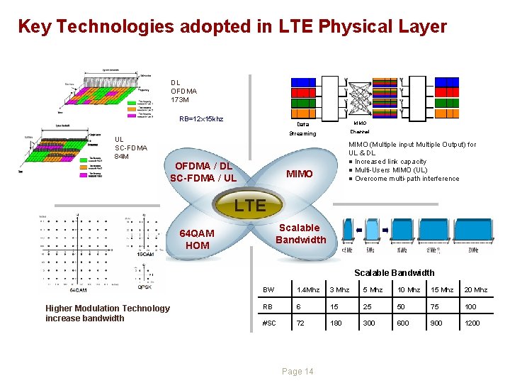
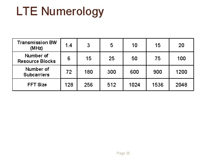
Key Technologies adopted in LTE Physical Layer DL OFDMA 173 M RB=12 x 15 khz UL SC-FDMA 84 M OFDMA / DL SC-FDMA / UL Data MIMO Streaming Channel MIMO (Multiple input Multiple Output) for UL & DL l Increased link capacity l Multi-Users MIMO (UL) l Overcome multi-path interference MIMO LTE Scalable Bandwidth 64 QAM HOM Scalable Bandwidth Higher Modulation Technology increase bandwidth BW 1. 4 Mhz 3 Mhz 5 Mhz 10 Mhz 15 Mhz 20 Mhz RB 6 15 25 50 75 100 #SC 72 180 300 600 900 1200 Page 14
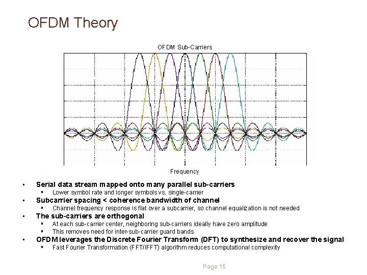
OFDM Theory OFDM Sub-Carriers Frequency • Serial data stream mapped onto many parallel sub-carriers § • Subcarrier spacing < coherence bandwidth of channel § • Channel frequency response is flat over a subcarrier, so channel equalization is not needed The sub-carriers are orthogonal § § • Lower symbol rate and longer symbols vs. single-carrier At each sub-carrier center, neighboring sub-carriers ideally have zero amplitude This removes need for inter-sub-carrier guard bands OFDM leverages the Discrete Fourier Transform (DFT) to synthesize and recover the signal § Fast Fourier Transformation (FFT/IFFT) algorithm reduces computational complexity Page 15
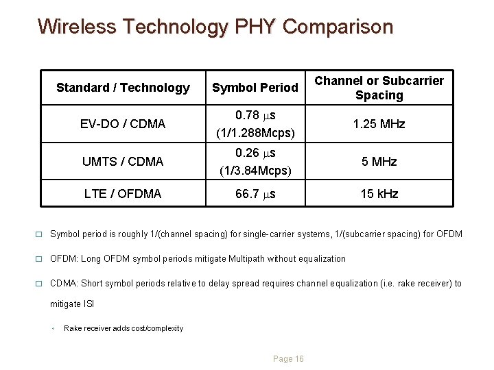
Wireless Technology PHY Comparison Standard / Technology Symbol Period Channel or Subcarrier Spacing EV-DO / CDMA 0. 78 ms (1/1. 288 Mcps) 1. 25 MHz UMTS / CDMA 0. 26 ms (1/3. 84 Mcps) 5 MHz LTE / OFDMA 66. 7 ms 15 k. Hz � Symbol period is roughly 1/(channel spacing) for single-carrier systems, 1/(subcarrier spacing) for OFDM � OFDM: Long OFDM symbol periods mitigate Multipath without equalization � CDMA: Short symbol periods relative to delay spread requires channel equalization (i. e. rake receiver) to mitigate ISI ◦ Rake receiver adds cost/complexity Page 16
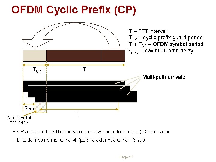
OFDM Cyclic Prefix (CP) T – FFT interval TCP – cyclic prefix guard period T + TCP – OFDM symbol period tmax – max multi-path delay TCP T Multi-path arrivals tmax ISI-free symbol start region T • CP adds overhead but provides inter-symbol interference (ISI) mitigation • LTE defines normal CP of 4. 7 ms and extended CP of 16. 7 ms Page 17
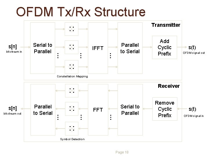
OFDM Tx/Rx Structure. . s[n] . . … . . IFFT … … bit-stream in Serial to Parallel Transmitter Parallel to Serial Add Cyclic Prefix s(t) OFDM signal out Constellation Mapping . . s[n] . . … . . FFT … … bit-stream out Parallel to Serial Receiver Serial to Parallel Symbol Detection Page 18 Remove Cyclic Prefix s(t) OFDM signal in
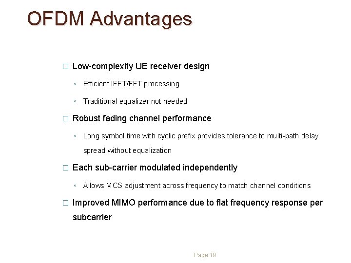
OFDM Advantages � Low-complexity UE receiver design ◦ Efficient IFFT/FFT processing ◦ Traditional equalizer not needed � Robust fading channel performance ◦ Long symbol time with cyclic prefix provides tolerance to multi-path delay spread without equalization � Each sub-carrier modulated independently ◦ Allows MCS adjustment across frequency to match channel conditions � Improved MIMO performance due to flat frequency response per subcarrier Page 19
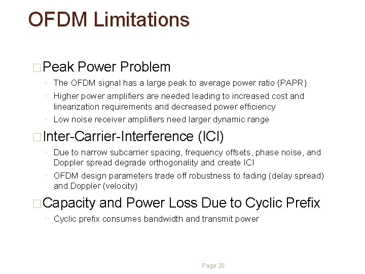
OFDM Limitations �Peak Power Problem ◦ The OFDM signal has a large peak to average power ratio (PAPR) ◦ Higher power amplifiers are needed leading to increased cost and linearization requirements and decreased power efficiency ◦ Low noise receiver amplifiers need larger dynamic range �Inter-Carrier-Interference (ICI) ◦ Due to narrow subcarrier spacing, frequency offsets, phase noise, and Doppler spread degrade orthogonality and create ICI ◦ OFDM design parameters trade off robustness to fading (delay spread) and Doppler (velocity) �Capacity and Power Loss Due to Cyclic Prefix ◦ Cyclic prefix consumes bandwidth and transmit power Page 20
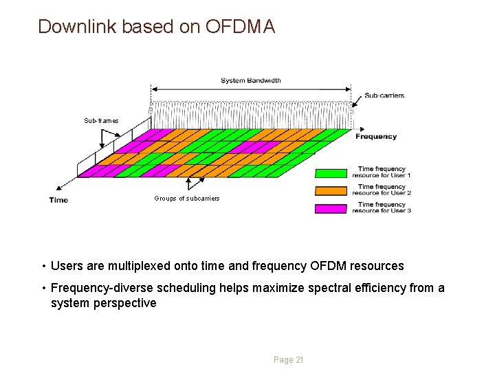
Downlink based on OFDMA Sub-frames Groups of subcarriers • Users are multiplexed onto time and frequency OFDM resources • Frequency-diverse scheduling helps maximize spectral efficiency from a system perspective Page 21
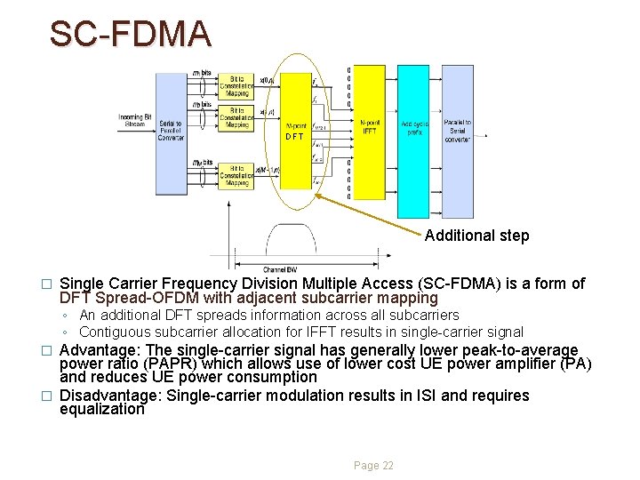
SC-FDMA DFT Additional step � Single Carrier Frequency Division Multiple Access (SC-FDMA) is a form of DFT Spread-OFDM with adjacent subcarrier mapping ◦ An additional DFT spreads information across all subcarriers ◦ Contiguous subcarrier allocation for IFFT results in single-carrier signal Advantage: The single-carrier signal has generally lower peak-to-average power ratio (PAPR) which allows use of lower cost UE power amplifier (PA) and reduces UE power consumption � Disadvantage: Single-carrier modulation results in ISI and requires equalization � Page 22
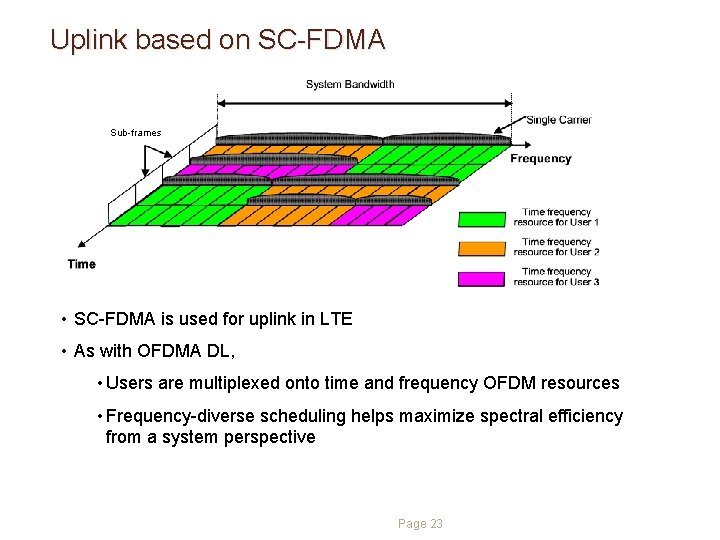
Uplink based on SC-FDMA Sub-frames • SC-FDMA is used for uplink in LTE • As with OFDMA DL, • Users are multiplexed onto time and frequency OFDM resources • Frequency-diverse scheduling helps maximize spectral efficiency from a system perspective Page 23
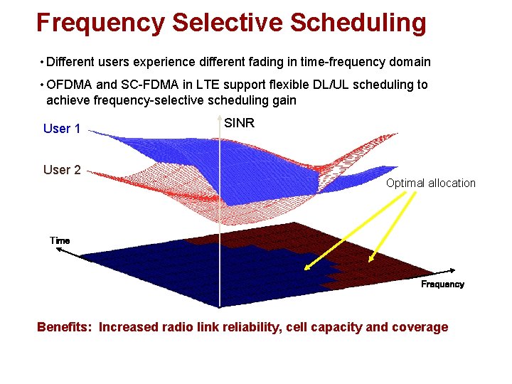
Frequency Selective Scheduling • Different users experience different fading in time-frequency domain • OFDMA and SC-FDMA in LTE support flexible DL/UL scheduling to achieve frequency-selective scheduling gain User 1 User 2 SINR Optimal allocation Time Frequency Benefits: Increased radio link reliability, cell capacity and coverage
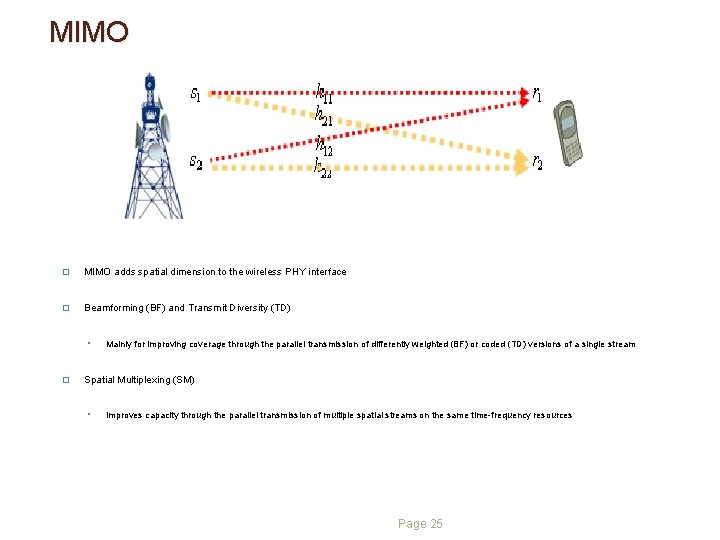
MIMO � MIMO adds spatial dimension to the wireless PHY interface � Beamforming (BF) and Transmit Diversity (TD) ◦ � Mainly for improving coverage through the parallel transmission of differently weighted (BF) or coded (TD) versions of a single stream Spatial Multiplexing (SM) ◦ Improves capacity through the parallel transmission of multiple spatial streams on the same time-frequency resources Page 25
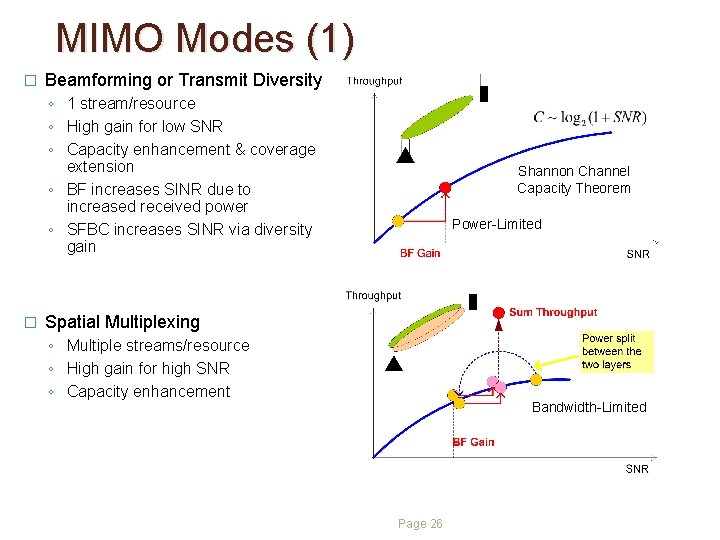
MIMO Modes (1) � Beamforming or Transmit Diversity ◦ 1 stream/resource ◦ High gain for low SNR ◦ Capacity enhancement & coverage extension ◦ BF increases SINR due to increased received power ◦ SFBC increases SINR via diversity gain � Shannon Channel Capacity Theorem Power-Limited Spatial Multiplexing ◦ Multiple streams/resource ◦ High gain for high SNR ◦ Capacity enhancement Bandwidth-Limited Page 26
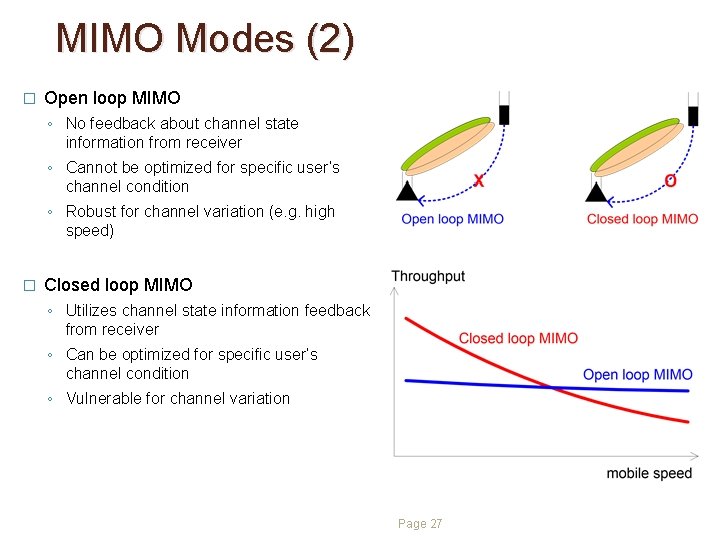
MIMO Modes (2) � Open loop MIMO ◦ No feedback about channel state information from receiver ◦ Cannot be optimized for specific user’s channel condition ◦ Robust for channel variation (e. g. high speed) � Closed loop MIMO ◦ Utilizes channel state information feedback from receiver ◦ Can be optimized for specific user’s channel condition ◦ Vulnerable for channel variation Page 27
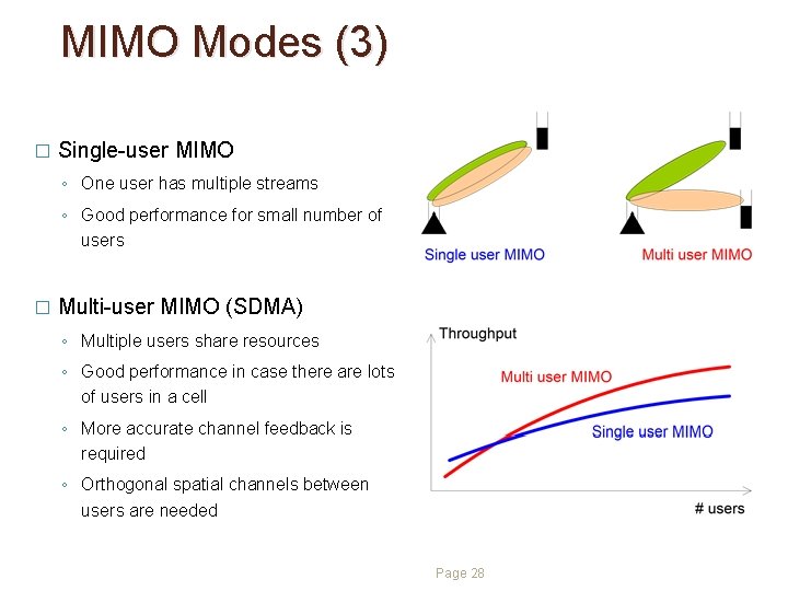
MIMO Modes (3) � Single-user MIMO ◦ One user has multiple streams ◦ Good performance for small number of users � Multi-user MIMO (SDMA) ◦ Multiple users share resources ◦ Good performance in case there are lots of users in a cell ◦ More accurate channel feedback is required ◦ Orthogonal spatial channels between users are needed Page 28
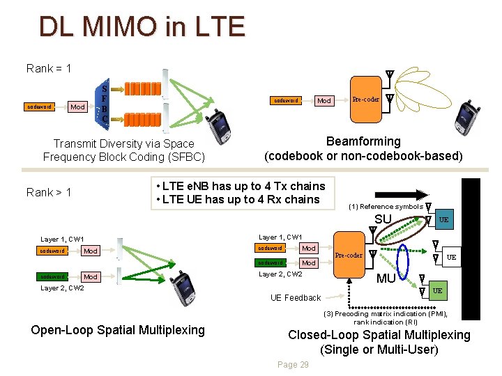
DL MIMO in LTE Rank = 1 codeword Mod S F B C Mod codeword Transmit Diversity via Space Frequency Block Coding (SFBC) Beamforming (codebook or non-codebook-based) (1) Reference symbols SU Layer 1, CW 1 codeword Mod Layer 2, CW 2 UE Feedback Open-Loop Spatial Multiplexing UE Pre-coder UE MU UE (3) Precoding matrix indication (PMI), rank indication (RI) (2) UEs determine best precoding matrix • LTE e. NB has up to 4 Tx chains • LTE UE has up to 4 Rx chains Rank > 1 Pre-coder Closed-Loop Spatial Multiplexing (Single or Multi-User) Page 29
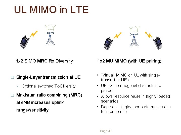
UL MIMO in LTE � 1 x 2 SIMO MRC Rx Diversity 1 x 2 MU MIMO (with UE pairing) Single-Layer transmission at UE • “Virtual” MIMO on UL with singletransmitter UEs • UEs with orthogonal channels are paired • Allows resource reuse in highly-loaded scenarios • Degrades single-user performance due to interference ◦ Optional switched Tx-Diversity � Maximum ratio combining (MRC) at e. NB increases uplink range/sensitivity Page 30
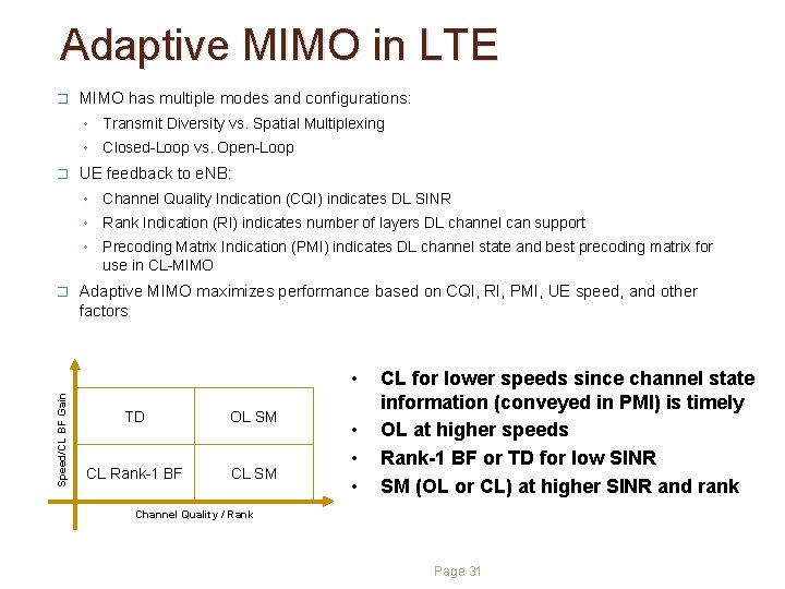
Adaptive MIMO in LTE � MIMO has multiple modes and configurations: ◦ Transmit Diversity vs. Spatial Multiplexing ◦ Closed-Loop vs. Open-Loop � UE feedback to e. NB: ◦ Channel Quality Indication (CQI) indicates DL SINR ◦ Rank Indication (RI) indicates number of layers DL channel can support ◦ Precoding Matrix Indication (PMI) indicates DL channel state and best precoding matrix for use in CL-MIMO � Adaptive MIMO maximizes performance based on CQI, RI, PMI, UE speed, and other factors Speed/CL BF Gain • TD OL SM CL Rank-1 BF CL SM • • • CL for lower speeds since channel state information (conveyed in PMI) is timely OL at higher speeds Rank-1 BF or TD for low SINR SM (OL or CL) at higher SINR and rank Channel Quality / Rank Page 31
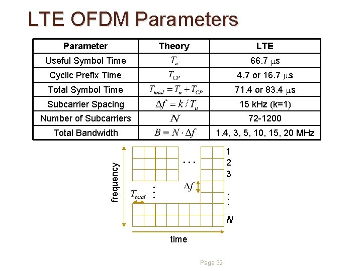
LTE OFDM Parameters Parameter Theory LTE 66. 7 ms Cyclic Prefix Time 4. 7 or 16. 7 ms Total Symbol Time 71. 4 or 83. 4 ms Subcarrier Spacing 15 k. Hz (k=1) Number of Subcarriers 72 -1200 Total Bandwidth 1. 4, 3, 5, 10, 15, 20 MHz 1 2 3 . . frequency Useful Symbol Time N time Page 32
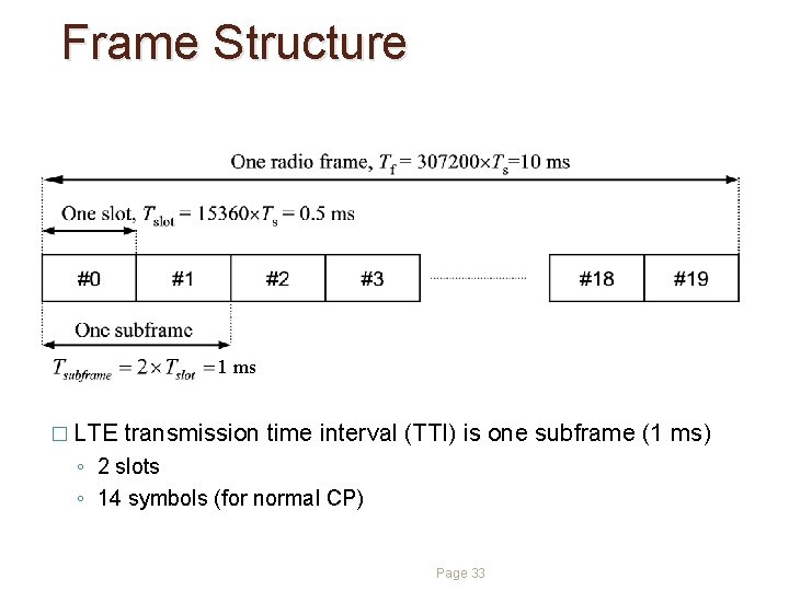
Frame Structure 1 ms � LTE transmission time interval (TTI) is one subframe (1 ms) ◦ 2 slots ◦ 14 symbols (for normal CP) Page 33
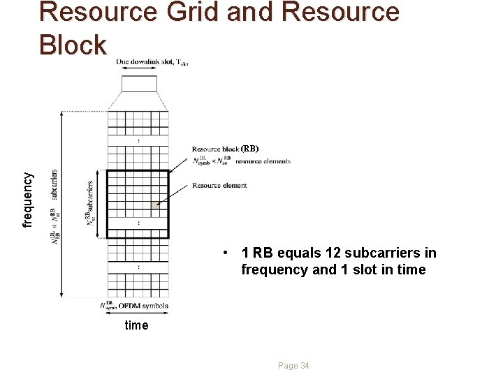
Resource Grid and Resource Block frequency (RB) • 1 RB equals 12 subcarriers in frequency and 1 slot in time Page 34
LTE Numerology Transmission BW (MHz) 1. 4 3 5 10 15 20 Number of Resource Blocks 6 15 25 50 75 100 Number of Subcarriers 72 180 300 600 900 1200 FFT Size 128 256 512 1024 1536 2048 Page 35
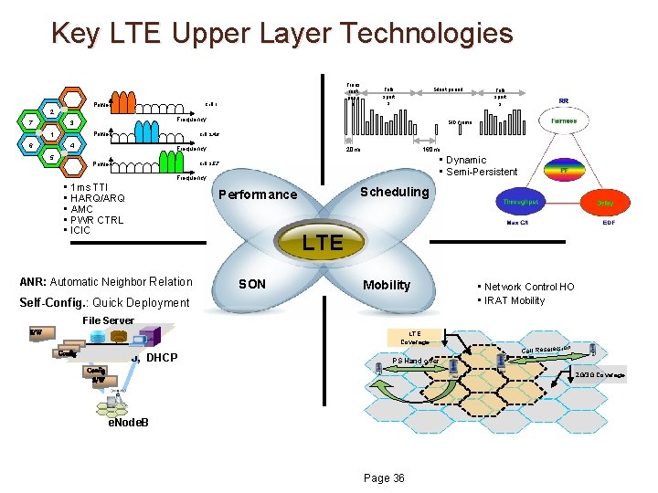
Key LTE Upper Layer Technologies Power 2 2 7 7 Cell 1 Power 6 6 4 4 5 5 Silent period Talk spurt s SID frame Cell 2, 4, 6 Frequency Power • • • Talk spurt s Frequency 3 3 1 1 Trans ient perio d 20 ms 160 ms • Dynamic • Semi-Persistent Cell 3, 5, 7 Frequency 1 ms TTI HARQ/ARQ AMC PWR CTRL ICIC ANR: Automatic Neighbor Relation Scheduling Performance LTE SON Mobility Self-Config. : Quick Deployment • Network Control HO • IRAT Mobility File Server S/W LTE Coverage Config M 2000, DHCP ion Cell Reselect PS Hand over Config S/W 2 G/3 G Coverage e. Node. B Page 36
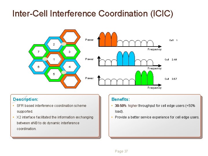
Inter-Cell Interference Coordination (ICIC) Power Cell 2 2 7 7 Frequency 3 3 1 1 6 6 1 Power 4 4 Cell 2, 4, 6 Cell 3, 5, 7 Frequency 5 5 Power Frequency Description: Benefits: • SFR based interference coordination scheme • 30 -50% higher throughput for cell edge users (<50% supported. • X 2 interface facilitated the information exchanging load). • Provide a better service experience for cell edge users. between e. NB to do dynamic interference coordination. Page 37
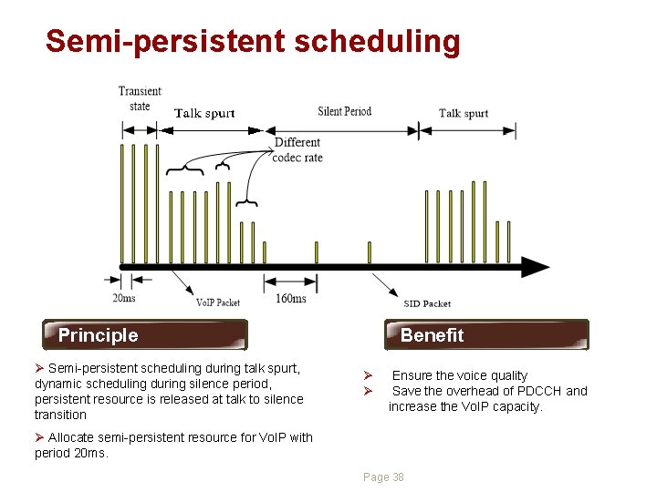
Semi-persistent scheduling Principle Ø Semi-persistent scheduling during talk spurt, dynamic scheduling during silence period, persistent resource is released at talk to silence transition Benefit Ø Ø Ensure the voice quality Save the overhead of PDCCH and increase the Vo. IP capacity. Ø Allocate semi-persistent resource for Vo. IP with period 20 ms. Page 38
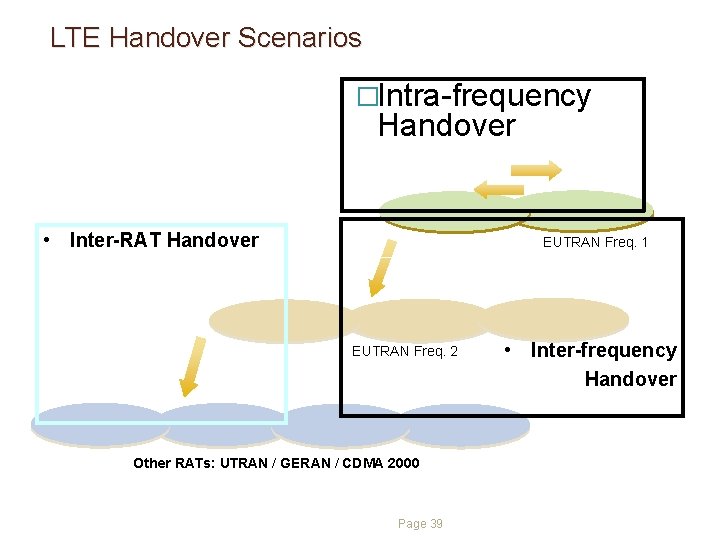
LTE Handover Scenarios �Intra-frequency Handover • Inter-RAT Handover EUTRAN Freq. 1 EUTRAN Freq. 2 Other RATs: UTRAN / GERAN / CDMA 2000 Page 39 • • Inter-frequency Handover
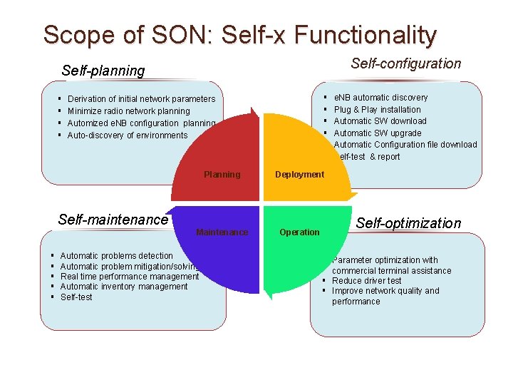
Scope of SON: Self-x Functionality Self-configuration Self-planning § § Self-maintenance § § § Derivation of initial network parameters Minimize radio network planning Automized e. NB configuration planning Auto-discovery of environments Planning Deployment Maintenance Operation Automatic problems detection Automatic problem mitigation/solving Real time performance management Automatic inventory management Self-test e. NB automatic discovery Plug & Play installation Automatic SW download Automatic SW upgrade Automatic Configuration file download Self-test & report Self-optimization § Parameter optimization with commercial terminal assistance § Reduce driver test § Improve network quality and performance
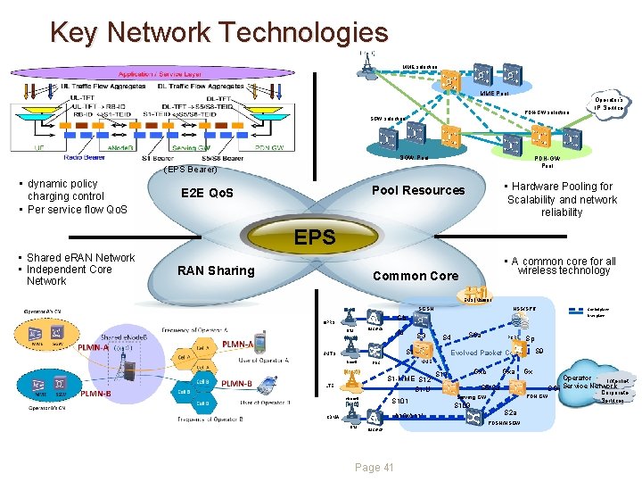
Key Network Technologies MME selection MME Pool PDN-GW selection Operator’s IP Service SGW selection SGW Pool PDN-GW Pool (EPS Bearer) • dynamic policy charging control • Per service flow Qo. S • Hardware Pooling for Scalability and network reliability Pool Resources E 2 E Qo. S EPS • Shared e. RAN Network • Independent Core Network RAN Sharing • A common core for all wireless technology Common Core EMS (M 2000) SGSN HSS/SPR GPRS BSC/PCU BTS Iu S 3 S 4 S 10 UMTS Node. B S 101 A 10/A 11’ CDMA BTS PCRF Sp S 9 Evolved Packet Core S 1 -MME S 12 S 1 -U e. Node. B S 6 a MME RNC LTE Control plane User plane Gb BSC/PCF Page 41 Gxc S 11 Gxa Gx S 5/S 8 PDN GW Serving GW S 103 S 2 a PDSN/HSGW Operator Internet SGi Service Network Corporate Services
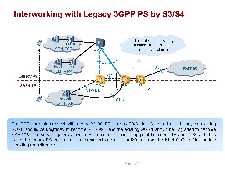
Interworking with Legacy 3 GPP PS by S 3/S 4 BTS Generally, these two logic functions are combined into one physical node. BSC/PCU GSM BSS SGSN S 3 Node. B S 4 RNC SGi UMTS RAN S 11 Legacy PS MME S 1 -MME SAE/LTE e. Node. B E-UTRAN Internet S-GW P-GW S 1 -U The EPC core interconnect with legacy 2 G/3 G PS core by S 3/S 4 interface. In this solution, the existing SGSN should be upgraded to become S 4 SGSN and the existing GGSN should be upgraded to become SAE GW. The serving gateway becomes the common anchoring point between LTE and 2 G/3 G. In this case, the legacy PS core can enjoy some enhancement of R 8, such as the label Qo. S profile, the idle signaling reduction etc. Page 42
LTE to e. HRPD PS HO with e. HRPD support Optimized Handover This solution introduces S 101 and S 103 interfaces. l The S 101 reference point is used to convey pre-registration and handoff signalling between EPS and EVDO. l The S 103 reference point is a user plane interface used to forward DL data to minimize packet losses in mobility from e. UTRAN to EVDO. The S 103 reference point supports the ability to tunnel traffic on a per-UE, per. PDN basis. Page 43
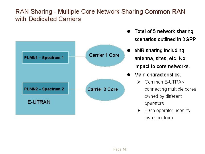
RAN Sharing - Multiple Core Network Sharing Common RAN with Dedicated Carriers l Total of 5 network sharing scenarios outlined in 3 GPP PLMN 1 – Spectrum 1 Carrier 1 Core l e. NB sharing including antenna, sites, etc. No impact to core networks. l Main characteristics: Ø Common E-UTRAN PLMN 2 – Spectrum 2 Carrier 2 Core connecting multiple cores owned by different E-UTRAN operators Ø Each operator uses its own spectrum Page 44
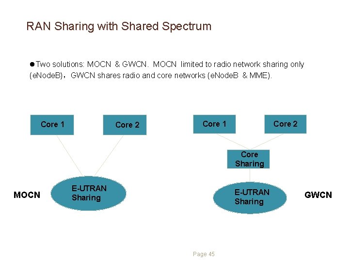
RAN Sharing with Shared Spectrum l. Two solutions: MOCN & GWCN. MOCN limited to radio network sharing only (e. Node. B),GWCN shares radio and core networks (e. Node. B & MME). Core 1 Core 2 Core Sharing MOCN E-UTRAN Sharing Page 45 GWCN
Contents 1 Market Drivers and Background (30 min) 2 LTE Technology Overview (75 min) 3 LTE Advanced Overview (30 min) 4 LTE Deployment Landscape (15 min) Page 46
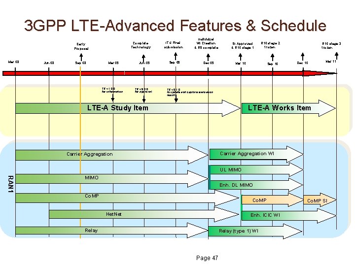
3 GPP LTE-Advanced Features & Schedule Complete Technology Early Proposal Mar 08 Jun 08 Sep 08 Mar 09 Jun 09 TR v 1. 0. 0 for information TR v 9. 0. 0 for approval ITU Final submission Sep 09 Individual WI Creation & R 9 complete Dec 09 SI Approved & R 10 stage 1 Mar 10 R 10 stage 2 frozen Sep 10 R 10 stage 3 frozen Dec 10 Mar 11 TR v 9. 1. 0 to update and capture evaluation results LTE-A Study Item LTE-A Works Item Carrier Aggregation WI Carrier Aggregation UL MIMO RAN 1 MIMO Enh. DL MIMO Co. MP Het. Net Enh. ICIC WI Relay (type 1) WI Page 47 Co. MP SI
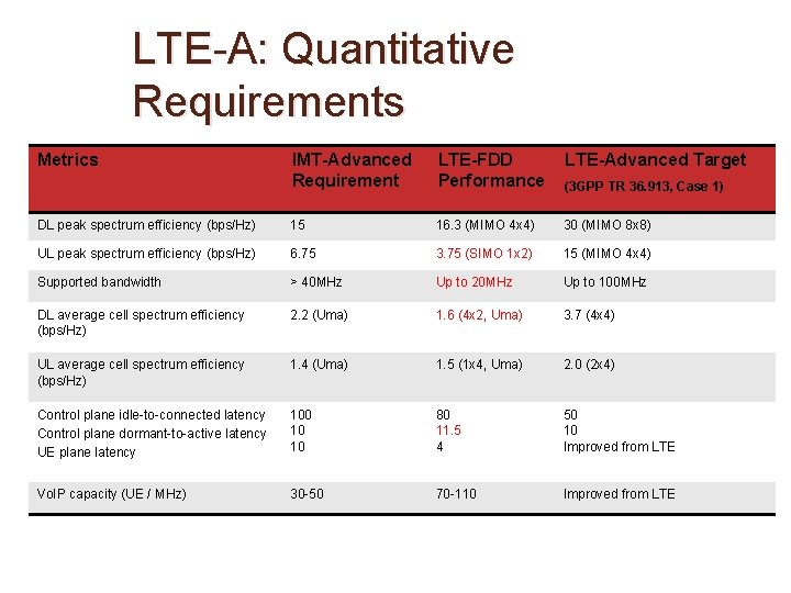
LTE-A: Quantitative Requirements Metrics IMT-Advanced Requirement LTE-FDD Performance LTE-Advanced Target (3 GPP TR 36. 913, Case 1) DL peak spectrum efficiency (bps/Hz) 15 16. 3 (MIMO 4 x 4) 30 (MIMO 8 x 8) UL peak spectrum efficiency (bps/Hz) 6. 75 3. 75 (SIMO 1 x 2) 15 (MIMO 4 x 4) Supported bandwidth > 40 MHz Up to 20 MHz Up to 100 MHz DL average cell spectrum efficiency (bps/Hz) 2. 2 (Uma) 1. 6 (4 x 2, Uma) 3. 7 (4 x 4) UL average cell spectrum efficiency (bps/Hz) 1. 4 (Uma) 1. 5 (1 x 4, Uma) 2. 0 (2 x 4) Control plane idle-to-connected latency Control plane dormant-to-active latency UE plane latency 100 10 10 80 11. 5 4 50 10 Improved from LTE Vo. IP capacity (UE / MHz) 30 -50 70 -110 Improved from LTE
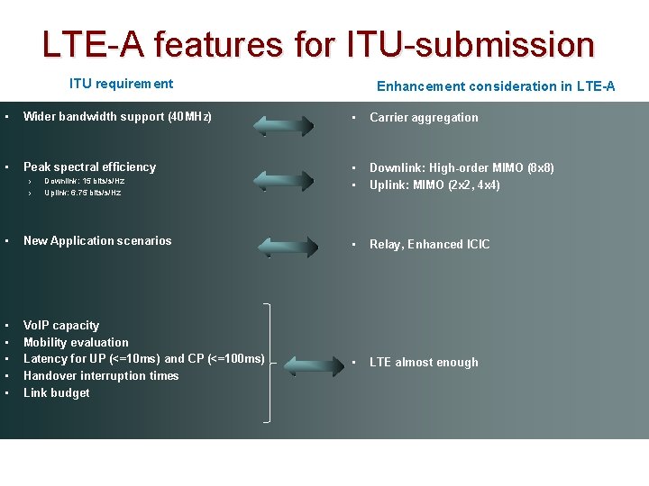
LTE-A features for ITU-submission ITU requirement Enhancement consideration in LTE-A • Wider bandwidth support (40 MHz) • Carrier aggregation • Peak spectral efficiency • • Downlink: High-order MIMO (8 x 8) Uplink: MIMO (2 x 2, 4 x 4) › › Downlink: 15 bits/s/Hz Uplink: 6. 75 bits/s/Hz • New Application scenarios • Relay, Enhanced ICIC • • • Vo. IP capacity Mobility evaluation Latency for UP (<=10 ms) and CP (<=100 ms) Handover interruption times Link budget • LTE almost enough
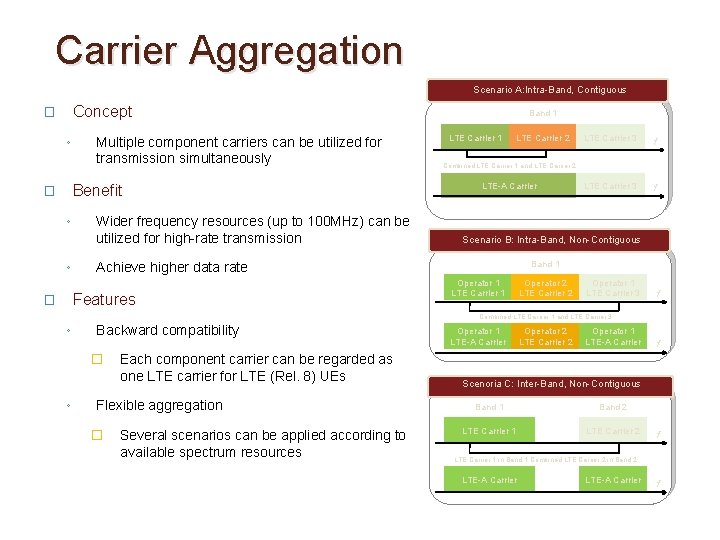
Carrier Aggregation Scenario A: Intra-Band, Contiguous Concept � ◦ Multiple component carriers can be utilized for transmission simultaneously Benefit � ◦ ◦ Wider frequency resources (up to 100 MHz) can be utilized for high-rate transmission ◦ LTE Carrier 2 LTE Carrier 3 f Combined LTE Carrier 1 and LTE Carrier 2 LTE-A Carrier Scenario B: Intra-Band, Non-Contiguous Band 1 Operator 1 LTE Carrier 1 Operator 2 LTE Carrier 2 Operator 1 LTE Carrier 3 f Combined LTE Carrier 1 and LTE Carrier 3 Backward compatibility � ◦ LTE Carrier 1 Achieve higher data rate Features � Band 1 Each component carrier can be regarded as one LTE carrier for LTE (Rel. 8) UEs Flexible aggregation � Several scenarios can be applied according to available spectrum resources Operator 1 LTE-A Carrier Operator 2 LTE Carrier 2 Operator 1 LTE-A Carrier f Scenoria C: Inter-Band, Non-Contiguous Band 1 Band 2 LTE Carrier 1 LTE Carrier 2 f LTE Carrier 1 in Band 1 Combined LTE Carrier 2 in Band 2 LTE-A Carrier f
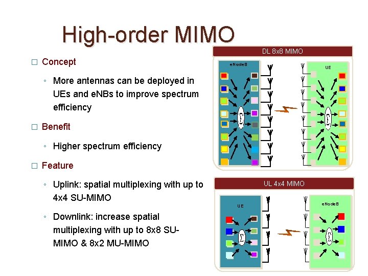
High-order MIMO � Concept DL 8 x 8 MIMO e. Node. B UE ◦ More antennas can be deployed in UEs and e. NBs to improve spectrum efficiency � Benefit ◦ Higher spectrum efficiency � Feature ◦ Uplink: spatial multiplexing with up to 4 x 4 SU-MIMO UL 4 x 4 MIMO UE ◦ Downlink: increase spatial multiplexing with up to 8 x 8 SUMIMO & 8 x 2 MU-MIMO e. Node. B
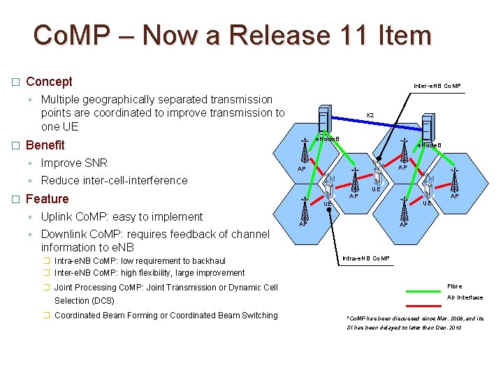
Co. MP – Now a Release 11 Item � Concept Inter-e. NB Co. MP ◦ Multiple geographically separated transmission points are coordinated to improve transmission to one UE � e. Node. B Benefit ◦ Improve SNR ◦ Reduce inter-cell-interference � X 2 � Intra-e. NB Co. MP: low requirement to backhaul � Inter-e. NB Co. MP: high flexibility, large improvement � Joint Processing Co. MP: Joint Transmission or Dynamic Cell Selection (DCS) � Coordinated Beam Forming or Coordinated Beam Switching AP AP UE Feature ◦ Uplink Co. MP: easy to implement ◦ Downlink Co. MP: requires feedback of channel information to e. NB e. Node. B AP UE UE AP AP AP Intra-e. NB Co. MP Fibre Air interface *Co. MP has been discussed since Mar. 2008, and its SI has been delayed to later than Dec. 2010
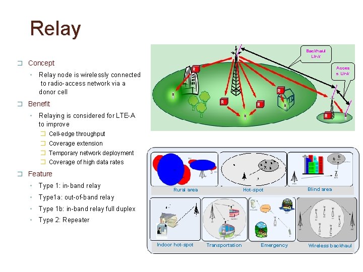
Relay Backhaul Link � Concept ◦ Acces s Link Relay node is wirelessly connected to radio-access network via a donor cell � Benefit ◦ Relaying is considered for LTE-A to improve � Cell-edge throughput � Coverage extension � Temporary network deployment � Coverage of high data rates � Feature ◦ Type 1: in-band relay ◦ Type 1 a: out-of-band relay ◦ Type 1 b: in-band relay full duplex ◦ Type 2: Repeater Rural area Indoor hot-spot Hot-spot Transportation Emergency Blind area Wireless backhaul
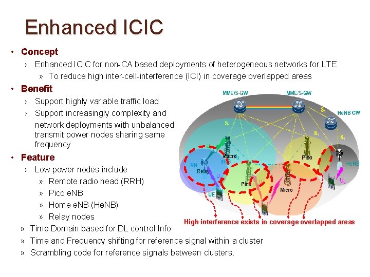
Enhanced ICIC • Concept › Enhanced ICIC for non-CA based deployments of heterogeneous networks for LTE » To reduce high inter-cell-interference (ICI) in coverage overlapped areas • Benefit › Support highly variable traffic load › Support increasingly complexity and network deployments with unbalanced transmit power nodes sharing same frequency • Feature › Low power nodes include » Remote radio head (RRH) » Pico e. NB » Home e. NB (He. NB) » Relay nodes High interference exists in coverage overlapped areas » Time Domain based for DL control Info » Time and Frequency shifting for reference signal within a cluster » Scrambling code for reference signals between clusters.
Contents 1 Market Drivers and Background (30 min) 2 LTE Technology Overview (75 min) 3 LTE Advanced Overview (30 min) 4 LTE Deployment Landscape (15 min) Page 55
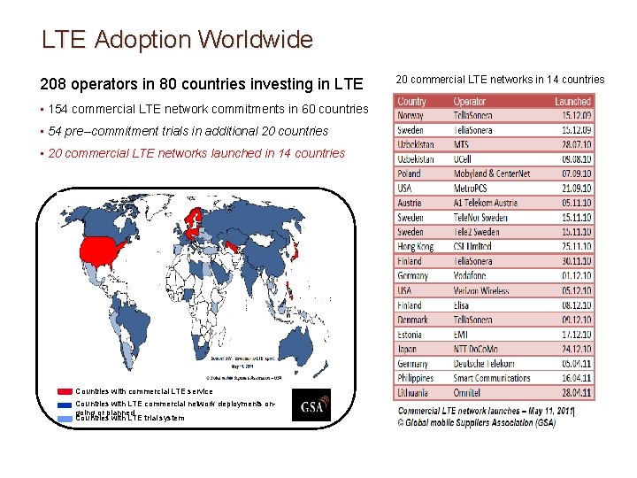
LTE Adoption Worldwide 208 operators in 80 countries investing in LTE • 154 commercial LTE network commitments in 60 countries • 54 pre--commitment trials in additional 20 countries • 20 commercial LTE networks launched in 14 countries Countries with commercial LTE service Countries with LTE commercial network deployments ongoing or planned Countries with LTE trial system 20 commercial LTE networks in 14 countries
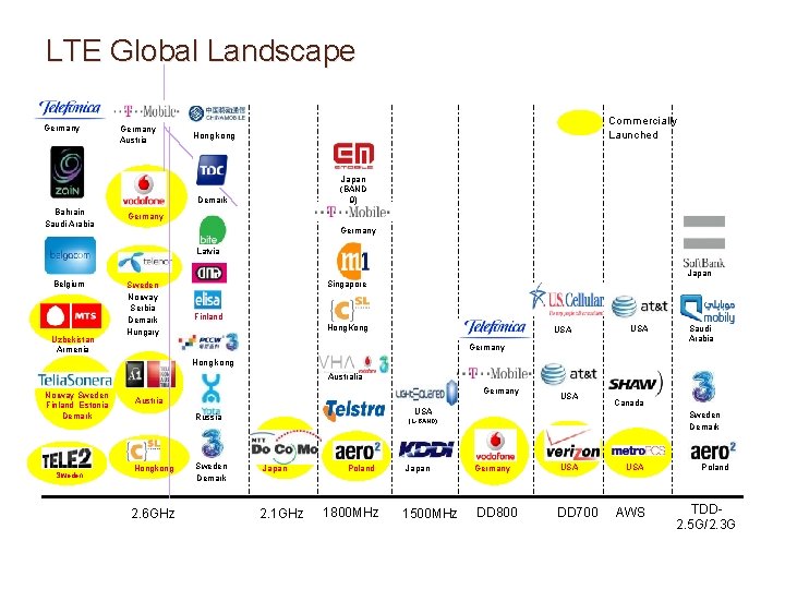
LTE Global Landscape Germany Austria Commercially Launched Hong kong Japan (BAND 9) Demark Bahrain Saudi Arabia Germany Latvia Japan Belgium Uzbekistan Armenia Sweden Norway Serbia Demark Hungary Singapore Finland Hong. Kong USA Germany Saudi Arabia Hong kong Australia Norway Sweden Finland Estonia Demark Sweden Germany Austria Russia Hongkong 2. 6 GHz Sweden Demark USA Canada Sweden Demark (L-BAND) Japan 2. 1 GHz Poland 1800 MHz Japan 1500 MHz Germany DD 800 USA DD 700 USA AWS Poland TDD 2. 5 G/2. 3 G
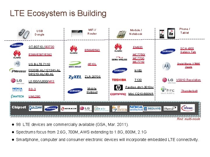
LTE Ecosystem is Building USB Dongle Mi. Fi / Router Module / Notebook GT-B 3710 / B 3730 EM 920 E 589/E 593 E 398/E 397/E 392 US B-LTE 7110 032038 -AL/ 121341 -AL 041213 -AL/ 40 -AL MC 7750/ MC 7700 MC 7710 4510 L UML 290 SCH-r 900 Galaxy Tab Droid Bionic XT 865 Xoom N 150 ZLR-2070 S T 130 LD 100/VL 600/M 13 RD-3 Phone / Tablet Mobile Hotspot VS 910 Resolution Pavilion dm 1 -3010 nr Mini CQ 10 -688 NR Thunderbolt Chipset Red: multi-mode l 98 LTE devices are commercially available (GSA, Mar. 2011). l Spectrums focus from 2. 6 G, 700 M, AWS extending to 1. 8 G, 800 M, 2. 1 G l Smartphone, computer and consumer electronic devices will incorporate embedded LTE connectivity.
THANK YOU!