COP 4710 Database Systems Spring 2013 Chapter 19

COP 4710: Database Systems Spring 2013 Chapter 19 – Normalization Instructor : Dr. Mark Llewellyn markl@cs. ucf. edu HEC 236, 407 -823 -2790 http: //www. cs. ucf. edu/courses/cop 4710/spr 2013 Department of Electrical Engineering and Computer Science Division University of Central Florida COP 4710: Database Systems (Chapter 19) Page 1 Dr.

Normalization • Normalization is a technique for producing a set of relations with desirable properties, given the data requirements of the enterprise being modeled. • The process of normalization was first developed by Codd in 1972. • Normalization is often performed as a series of tests on a relation to determine whether it satisfies or violates the requirements of a given normal form. • Codd initially defined three normal forms called first (1 NF), second (2 NF), and third (3 NF). Boyce and Codd together introduced a stronger definition of 3 NF called Boyce-Codd Normal Form (BCNF) in 1974. COP 4710: Database Systems (Chapter 19) Page 2 Dr.

Normalization (cont. ) • All four of these normal forms are based on functional dependencies among the attributes of a relation. • A functional dependency describes the relationship between attributes in a relation. – • For example, if A and B are attributes or sets of attributes of relation R, B is functionally dependent on A (denoted A B), if each value of A is associated with exactly one value of B. In 1977 and 1979, a fourth (4 NF) and fifth (5 NF) normal form were introduced which go beyond BCNF. However, they deal with situations which are quite rare. Other higher normal forms have been subsequently introduced, but all of them are based on dependencies more involved than functional dependencies. COP 4710: Database Systems (Chapter 19) Page 3 Dr.

Normalization (cont. ) • A relational schema consists of a number of attributes, and a relational database schema consists of a number of relations. • Attributes may grouped together to form a relational schema based largely on the common sense of the database designer, or by mapping the relational schema from an ER model. • Whatever approach is taken, a formal method is often required to help the database designer identify the optimal grouping of attributes for each relation in the database schema. • The process of normalization is a formal method that identifies relations based on their primary or candidate keys and the functional dependencies among their attributes. • Normalization supports database designers through a series of tests, which can be applied to individual relations so that a relational schema can be normalized to a specific form to prevent the possible occurrence of update anomalies. COP 4710: Database Systems (Chapter 19) Page 4 Dr.

Data Redundancy and Update Anomalies • The major aim of relational database design is to group attributes into relations to minimize data redundancy and thereby reduce the file storage space required by the implemented base relations. • Consider the following relation schema: staffbranch staff# sname position salary branch# baddress SL 21 Kristy manager 30000 B 005 22 Deer Road SG 37 Debi assistant 12000 B 003 162 Main Street SG 14 Alan supervisor 18000 B 003 163 Main Street SA 9 Traci assistant 12000 B 007 375 Fox Avenue SG 5 David manager 24000 B 003 163 Main Street SL 41 Anna assistant 10000 B 005 22 Deer Road COP 4710: Database Systems (Chapter 19) Page 5 Dr.

Introduction To Normalization • In general, the goal of a relational database design is to generate a set of relation schemas that create an accurate representation of the real-world situation that is being modeled. – The design must also allow information to be stored without unnecessary redundancy, yet also allow for that information to be retrieved efficiently. • A technique that can be used to identify this set of suitable relational schemas is called normalization. • The process of normalization builds a set of schemas, each of which is in an appropriate normal form. • Normalization is a bottom-up approach to database design that begins by examining the relationships between attributes. • To determine if a relation schema is in one of the desirable normal forms, additional information is required about the real-world scenario that is being modeled. Most of this additional information is represented by a type of data dependency known as a functional dependency. COP 4710: Database Systems (Chapter 19) Page 6 Dr.

Introduction To Normalization • The process of normalization can be defined formally as: Normalization: A technique for producing a set of relational schemas with desirable properties given the data requirements pertaining to the real-world situation that is being modeled. • The process of normalization was first developed in the early 1970 s by E. F. Codd. • Normalization is most often performed as a series of tests on a relational schema to determine whether it satisfies or violates the requirements of a given normal form. • Codd initially proposed three normal forms called first (1 NF), second (2 NF), and third (3 NF). Subsequently, R. Boyce and Codd together introduced a stronger definition for third normal form called Boyce-Codd Normal Form (BCNF). • All four of these normal forms are based upon the concept of a functional dependency. Higher normal forms that go beyond BCNF, such as fourth (4 NF) and fifth (5 NF), as well as several others, have also subsequently been introduced. These higher normal forms utilize other types of data dependencies and some of these apply to situations that are quite rare. We will concentrate only on the first four normal forms and not examine any of the higher normal forms. COP 4710: Database Systems (Chapter 19) Page 7 Dr.

Relationship Between Normal Forms N 1 NF 2 NF 3 NF BCNF 4 NF 5 NF Higher Normal Forms COP 4710: Database Systems (Chapter 19) Page 8 Dr.

Introduction To Normalization • The process of normalization is a formal method that identifies relational schemas based upon their primary or candidate keys and the functional dependencies that exists amongst their attributes. • Normalization is primarily a tool to validate and improve a logical design so that it satisfies certain constraints that avoid unnecessary duplication of data. • Normalization is the process of decomposing relations with anomalies to produce smaller, well-structured relations. COP 4710: Database Systems (Chapter 19) Page 9 Dr.

Introduction To Normalization • A well-structured relation contains minimal data redundancy and allows users to insert, delete, and update rows without causing data inconsistencies. • Goal is to avoid anomalies – Insertion Anomaly – adding new rows forces user to create duplicate data. – Deletion Anomaly – deleting rows may cause a loss of data that would be needed for other future rows. – Modification Anomaly – changing data in a row forces changes to other rows because of duplication. COP 4710: Database Systems (Chapter 19) Page 10 Dr.

Example – Anomalies In A Relation Question – Is this a relation? Answer – Yes: unique rows and no multivalued attributes Question – What’s the primary key? COP 4710: Database Systems (Chapter 19) Answer – Composite: Emp_ID, Course_Title Page 11 Dr.

Anomalies in this Table • Insertion – can’t enter a new employee without having the employee take a class. • Deletion – if we remove employee 140, we lose information about the existence of a Tax Acc class. • Modification – giving a salary increase to employee 100 forces us to update multiple records. Why do these anomalies exist? Because there are two themes (entity types) into one relation. This results in duplication, and an unnecessary dependency between the entities General rule of thumb: a table should not pertain to more than one entity type COP 4710: Database Systems (Chapter 19) Page 12 Dr.

Brief Overview Of The Steps in Normalization • First Normal Form (1 NF): All multi-valued attributes have been removed from the table. Only a single value (possibly null) exists at the intersection of each row and column of the table. • Second Normal Form (2 NF): All partial functional dependencies have been removed. [Non-key attributes are identified by only the full primary key. ] • Third Normal Form (3 NF): All transitive functional dependencies have been removed. [Non-key attributes are identified by only the primary key. ] • Boyce-Codd Normal Form (BCNF): Any remaining anomalies that result from functional dependencies have been removed. [More than one primary key existed for the same non-key attributes. ] COP 4710: Database Systems (Chapter 19) Page 13 Dr.

Brief Overview Of The Steps in Normalization Figure 5 -22, page 212 COP 4710: Database Systems (Chapter 19) Page 14 Dr.

Important Note • The design of a relational database should have included a conceptual modeling step (producing an ER diagram) for the enterprise (as we have done). • This step was followed by a transformation process that converted the ER diagram into a set of relational tables. • The first step in the transformation process generated a table (relation) for every multi-valued attribute for a given entity. • This means that every table (relation) that was created was in fact a relation and thus is in 1 NF. • In our earlier discussion of anomalies, the table was in 1 NF but was not a well-structured table as it contained certain anomalies. Normalization will remove these anomalies. COP 4710: Database Systems (Chapter 19) Page 15 Dr.

Functional Dependencies • A functional dependency is a constraint between two attributes (or sets of attributes). – For any relation R, attribute B is functionally dependent on attribute A if, for every valid instance of A, that value of A uniquely determines the value of B. – The functional dependency of B on A is denoted as: A → B. consequent • Example: EMP_COURSE (Emp_ID, Course_Title, Date_Completed) The relation instance shown on the right determinant Emp_ID Course_Title Date_Completed satisfies the functional dependency 100 Excel 4/1/2009 Emp_ID, Course_Title → Date_Completed 100 Access 5/20/2010 140 Tax Acct. 3/14/2004 110 Visual Basic 6/6/2006 110 C++ 11/16/2008 150 Excel 6/27/2007 150 Access 8/12/2009 COP 4710: Database Systems (Chapter 19) Page 16 Dr.

A 1 NF, But Not Well-structured, Table COP 4710: Database Systems (Chapter 19) Page 17 Dr.

Anomalies in this Table • Insertion – if new product is ordered for order 1007 of existing customer, customer data must be re-entered, causing duplication. • Deletion – if we delete the Dining Table from Order 1006, we lose information concerning this item's finish and price. • Update – changing the price of product ID 4 requires update in several records. COP 4710: Database Systems (Chapter 19) Page 18 Dr.

Functional Dependencies in this Table COP 4710: Database Systems (Chapter 19) Page 19 Dr.

Definition of 2 NF • A relation is in 2 NF if it is in 1 NF and every non-key attribute is fully functionally dependent on the ENTIRE primary key. – Every non-key attribute must be defined by the entire key, not by only part of the key. (A partial dependency exists whenever a non-key attribute is functionally dependent on only a portion of the primary key. ) – No partial functional dependencies exist in a 2 NF relation. COP 4710: Database Systems (Chapter 19) Page 20 Dr.

Why INVOICE Table Is Not In 2 NF Order_ID Order_Date, Customer_ID, Customer_Name, Customer_Address Product_ID Product_Description, Product_Finish, Unit_Price Therefore, NOT in 2 nd Normal Form COP 4710: Database Systems (Chapter 19) Page 21 Dr.

Converting A N 2 NF Relation Into A 2 NF Relation • To convert a relation containing partial dependencies into a 2 NF relation, the following steps are required: 1. Create a new relation for each primary key attributed (or combinations of attributes) that is a determinant in a partial dependency. That attribute is the primary key in the new relation. 2. Move the non-key attributes that are dependent on this primary key attribute (or attributes) from the old relation into the new relation. COP 4710: Database Systems (Chapter 19) Page 22 Dr.

Converting A N 2 NF Relation Into A 2 NF Relation EXAMPLE COP 4710: Database Systems (Chapter 19) Page 23 Dr.

Consequences of the Definition of 2 NF • A 1 NF relation will be in 2 NF if any of the following conditions hold: 1. The primary key consists of only one attribute. By definition, there cannot be a partial dependency in such a relation. 2. No non-key attributes exists in the relation (all of the attributes in the relation are part of the primary key). By definition there are no functional dependencies (other than the trivial ones) in such a relation. 3. Every non-key attribute is functionally dependent on the full set of primary key attributes. COP 4710: Database Systems (Chapter 19) Page 24 Dr.

Definition of 3 NF • A relation is in 3 NF if it is in 2 NF and every no transitive dependencies exist. – A transitive dependency in a relation is a functional dependency between two (or more) non-key attributes. – Primary. Key → A→ B. Order_ID → Customer_ID -and. Customer_ID → Customer_Name Customer_ID → Customer_Address COP 4710: Database Systems (Chapter 19) Page 25 Dr.

Converting A N 3 NF Relation Into A 3 NF Relation • To convert a relation containing transitive dependencies into a 3 NF relation, the following steps are required: 1. For each non-key attributed (or set of attributed) that is a determinant in the relation, create a new relation. That attribute (or set of attributes) becomes the primary key in the new relation. 2. Move all of the attributes that are functionally dependent on the attribute from the old relation into the new relation. 3. Leave the attribute (which serves as the primary key in the new relation) in the old relation to serve as a foreign key that allows an association between the two relation. COP 4710: Database Systems (Chapter 19) Page 26 Dr.

Converting A N 3 NF Relation Into A 3 NF Relation EXAMPLE COP 4710: Database Systems (Chapter 19) Page 27 Dr.

Data Redundancy and Update Anomalies (cont. ) • The examples of three types of update anomalies suffered by the relation in the previous few pages demonstrate that its decomposition relations avoids such anomalies. • There are two important properties associated with the decomposition of a larger relation into a set of smaller relations. 1. The lossless-join property ensures that any instance of the original relation can be identified from corresponding instances of the smaller relations. 2. The dependency preservation property ensures that a constraint on the original relation can be maintained by simply enforcing some constraint on each of the smaller relations. In other words, the smaller relations do not need to be joined together to check if a constraint on the original relation is violated. COP 4710: Database Systems (Chapter 19) Page 28 Dr.

The Lossless Join Property • Consider the following relation schema SP and its decomposition into two schemas S 1 and S 2. SP S 1 S 2 s# p# qty s# qty p# qty S 1 P 1 10 S 1 10 P 1 10 S 2 P 2 50 S 2 50 P 2 50 S 3 P 3 10 S 3 10 P 3 10 s# p# qty S 1 P 1 10 S 1 P 3 10 S 2 P 2 10 S 3 P 1 10 S 3 P 3 10 These are extraneous tuples which did not appear in the original relation. However, now we can’t tell which are valid and which aren’t. Once the decomposition occurs the original SP relation is lost. COP 4710: Database Systems (Chapter 19) Page 29 Dr.

Preservation of the Functional Dependencies Example R = (A, B, C) F = {AB C, C A} = {(B, C), (A, C)} Clearly C A can be enforced on schema (A, C). How can AB C be enforced without joining the two relation schemas in ? Answer, it can’t, therefore the fds are not preserved in . COP 4710: Database Systems (Chapter 19) Page 30 Dr.

Summary of Normal Forms Property 3 NF BCNF 4 NF Eliminates redundancy due to functional dependencies most yes Eliminates redundancy due to multi-valued dependencies no no yes Preserves functional dependencies yes maybe Preserves multi-valued dependencies maybe Has the lossless join property yes yes COP 4710: Database Systems (Chapter 19) Page 31 Dr.

Denormalization • Denormalization is the process of transforming normalized relations into non-normalized physical record specifications. • In a modern computer system, the cost per unit of storage (memory) has decreased drastically in recent years, Thus, while it is still a consideration, the efficient use of storage space has become less important than in the past. • In a modern DBMS, efficient data processing dominates the design process. In other words, speed not style takes precedence. • Efficient processing of data is in part dependent on how close related data are maintained in memory. COP 4710: Database Systems (Chapter 19) Page 32 Dr.

Denormalization • As we’ve just seen, the normalization process tends to distribute the data into many tables. • It is often the case that all of the attributes that appear within a relation are not used together, and data from different relations are needed to be combined together to answer a query or produce a report. • Although normalized relations solve data maintenance anomalies and minimize redundancy (and hence reduce storage space requirements), if implemented as one for one physical records, will probably not yield efficient data processing. COP 4710: Database Systems (Chapter 19) Page 33 Dr.

Denormalization • A fully normalized database generally contains a large number of relations. For a frequently executed query that requires data from multiple, related tables, the DBMS can spend a considerable amount of time each time the query is executed in matching the related rows (joining rows) from each relation that is required to build the query result. • Since join operations can be quite time consuming, the processing performance differential between totally normalized and partially normalized (denormalized) databases can be quite dramatic. COP 4710: Database Systems (Chapter 19) Page 34 Dr.

Denormalization • In general, denormalization may partition a relation into several physical records, may combine attributes from several relations together into one physical record, or a combination of both. • There are, in general, three common types of denormalization that occur: – Two entities with a 1: 1 relationship between them. – A N: M relationship (associative entity) with non-key attributes. – Reference data. • We’ll look more closely at each of these types on the next few pages. COP 4710: Database Systems (Chapter 19) Page 35 Dr.

Denormalization Case: 1: 1 Binary Relationship • Even in cases where one of the entities is an optional participant, if the matching entity exists most of the time, then it may be wise to combine these two relations into one record definition. This would be especially true if the access frequency between the two entity types is high). • Consider the example shown on the next page. The ERD shows student data with optional data from a standard scholarship application a student might complete. • In this case, one record could be formed with four fields from the Student and Application normalized relations. • Note that in this case the attributes from the optional entity must be allowed to have null values. COP 4710: Database Systems (Chapter 19) Page 36 Dr.

Denormalization Case: 1: 1 Binary Relationship COP 4710: Database Systems (Chapter 19) Page 37 Dr.

Denormalization Case: N: M (Associative Entity) • In this case, rather than joining three files in order to extract data from the two basic entities in the relationship, it might be advisable to combine attributes from one of the entities into the record representing the N: M relationship and thus avoid one of the join operations. • This would be most advantageous if this joining occurs frequently. • The example on the next page illustrates this situation with price quotes for various items from different vendors. In this situation, attributes from the Item and Price Quote relations might be combined into one record to prevent the three table join operation. • Note that this may create considerable duplication of data, since the Item attributes, such as Description, would repeat for each price quote. This would require excessive updating if duplicated data changed. Analysis of a composite usage map to study access frequencies and the number of occurrences of Price Quote per associated Vendor or Item would be essential to understand the consequences of such denormalization. COP 4710: Database Systems (Chapter 19) Page 38 Dr.

Denormalization Case: N: M (Associative Entity) Extra table access is required Null Description would be possible COP 4710: Database Systems (Chapter 19) Page 39 Dr.

Denormalization Case: Reference Data • Reference data exist in an entity on one side of a 1: M relationship, and this entity participates in no other relationships. • When this situation arises, you should seriously consider merging the two entities into one physical record definition when there are few instances of the entity on the many side for each entity instance on the one side. • The following page illustrates this situation, in which several Items have the same Storage Instructions and Storage Instructions relates only to Items. In this case, the storage instructions could be stored in the Item record, • Note that in so doing, redundancy and the potential for extra data maintenance will increase. COP 4710: Database Systems (Chapter 19) Page 40 Dr.

Denormalization Case: N: M (Associative Entity) Extra table access is required Data duplication COP 4710: Database Systems (Chapter 19) Page 41 Dr.

Functional Dependencies • For our discussion on functional dependencies (fds), assume that a relational schema has attributes (A, B, C, . . . , Z) and that the whole database is described by a single universal relation called R = (A, B, C, . . . , Z). This assumption means that every attribute in the database has a unique name. • A functional dependency is a property of the semantics of the attributes in a relation. The semantics indicate how attributes relate to one another, and specify the functional dependencies between attributes. • When a functional dependency is present, the dependency is specified as a constraint between the attributes. COP 4710: Database Systems (Chapter 19) Page 42 Dr.

Functional Dependencies (cont. ) • Consider a relation with attributes A and B, where attribute B is functionally dependent on attribute A. If we know the value of A and we examine the relation that holds this dependency, we will find only one value of B in all of the tuples that have a given value of A, at any moment in time. Note however, that for a given value of B there may be several different values of A. A • B is functionally dependent on A B The determinant of a functional dependency is the attribute or group of attributes on the left-hand side of the arrow in the functional dependency. The consequent of a fd is the attribute or group of attributes on the right-hand side of the arrow. – In the figure above, A is the determinant of B and B is the consequent of A. COP 4710: Database Systems (Chapter 19) Page 43 Dr.

Identifying Functional Dependencies • Look back at the staff relation on page 6. The functional dependency staff# position clearly holds on this relation instance. However, the reverse functional dependency position staff# clearly does not hold. – The relationship between staff# and position is 1: 1 (from staff to position) – for each staff member there is only one position. On the other hand, the relationship between position and staff# is 1: M – there are several staff numbers associated with a given position. staff# position • position is functionally dependent on staff# position staff# is NOT functionally dependent on position staff# For the purposes of normalization we are interested in identifying functional dependencies between attributes of a relation that have a 1: 1 relationship. COP 4710: Database Systems (Chapter 19) Page 44 Dr.

Identifying Functional Dependencies (cont. ) • When identifying fds between attributes in a relation it is important to distinguish clearly between the values held by an attribute at a given point in time and the set of all possible values that an attributes may hold at different times. • In other words, a functional dependency is a property of a relational schema (its intension) and not a property of a particular instance of the schema (extension). • The reason that we need to identify fds that hold for all possible values for attributes of a relation is that these represent the types of integrity constraints that we need to identify. Such constraints indicate the limitations on the values that a relation can legitimately assume. In other words, they identify the legal instances which are possible. COP 4710: Database Systems (Chapter 19) Page 45 Dr.

Identifying Functional Dependencies (cont. ) • Let’s identify the functional dependencies that hold using the relation schema staffbranch shown on page 5 as an example. • In order to identify the time invariant fds, we need to clearly understand the semantics of the various attributes in each of the relation schemas in question. – For example, if we know that a staff member’s position and the branch at which they are located determines their salary. There is no way of knowing this constraint unless you are familiar with the enterprise, but this is what the requirements analysis phase and the conceptual design phase are all about! staff# sname, position, salary, branch#, baddress branch# baddress branch#, position salary baddress, position salary COP 4710: Database Systems (Chapter 19) Page 46 Dr.

Identifying Functional Dependencies • (cont. ) It is common in many textbooks to use diagrammatic notation for displaying functional dependencies (this is how your textbook does it). An example of this is shown below using the relation schema staffbranch shown on page 5 for the fds we just identified as holding on the relational schema. staff# sname, position, salary, branch#, baddress branch# baddress branch#, position salary baddress, position salary staffbranch staff# sname position salary COP 4710: Database Systems (Chapter 19) branch# baddress Page 47 Dr.

Trivial Functional Dependencies • As well as identifying fds which hold for all possible values of the attributes involved in the fd, we also want to ignore trivial functional dependencies. • A functional dependency is trivial iff, the consequent is a subset of the determinant. In other words, it is impossible for it not to be satisfied. – Example: Using the relation instances on page 6, the trivial dependencies include: { staff#, sname} sname { staff#, sname} staff# • Although trivial fds are valid, they offer no additional information about integrity constraints for the relation. As far as normalization is concerned, trivial fds are ignored. COP 4710: Database Systems (Chapter 19) Page 48 Dr.

Summary of FD Characteristics • In summary, the main characteristics of functional dependencies that are useful in normalization are: 1. There exists a 1: 1 relationship from the attribute(s) in the determinant to the attribute(s) in the consequent. 2. The functional dependency is time invariant, i. e. , it holds in all possible instances of the relation. 3. The functional dependencies are nontrivial. ignored. COP 4710: Database Systems (Chapter 19) Page 49 Trivial fds are Dr.

Inference Rules for Functional Dependencies • We’ll denote as F, the set of functional dependencies that are specified on a relational schema R. • Typically, the schema designer specifies the fds that are semantically obvious; usually however, numerous other fds hold in all legal relation instances that satisfy the dependencies in F. • These additional fds that hold are those fds which can be inferred or deduced from the fds in F. • The set of all functional dependencies implied by a set of functional dependencies F is called the closure of F and is denoted F+. COP 4710: Database Systems (Chapter 19) Page 50 Dr.

Inference Rules (cont. ) • The notation: F ⊨ X Y denotes that the functional dependency X Y is implied by the set of fds F. • Formally, F+ {X Y | F ⊨ X Y } • A set of inference rules is required to infer the set of fds in F+. – • For example, if I tell you that Kristi is older than Debi and that Debi is older than Traci, you are able to infer that Kristi is older than Traci. How did you make this inference? Without thinking about it or maybe knowing about it, you utilized a transitivity rule to allow you to make this inference. The next page illustrates a set of six well-known inference rules that apply to functional dependencies. COP 4710: Database Systems (Chapter 19) Page 51 Dr.

Inference Rules (cont. ) IR 1: reflexive rule – if X Y, then X Y IR 2: augmentation rule – if X Y, then XZ YZ IR 3: transitive rule – if X Y and Y Z, then X Z IR 4: projection rule – if X YZ, then X Y and X Z IR 5: additive rule – if X Y and X Z, then X YZ IR 6: pseudotransitive rule – if X Y and YZ W, then XZ W • The first three of these rules (IR 1 -IR 3) are known as Armstrong’s Axioms and constitute a necessary and sufficient set of inference rules for generating the closure of a set of functional dependencies. COP 4710: Database Systems (Chapter 19) Page 52 Dr.

Example Proof Using Inference Rules • Given R = (A, B, C, D, E, F, G, H, I, J) and F = {AB E, AG J, BE I, E G, GI H} does F ⊨ AB GH? Proof 1. 2. 3. 4. 5. 6. 7. 8. 9. 10. 11. 12. Practice Problem AB E, given in F Using the same set F, prove AB AB, reflexive rule IR 1 that F ⊨ BE H AB B, projective rule IR 4 from step 2 AB BE, additive rule IR 5 from steps 1 and 3 Answer: on next page/ BE I, given in F AB I, transitive rule IR 3 from steps 4 and 5 E G, given in F AB G, transitive rule IR 3 from steps 1 and 7 AB GI, additive rule IR 5 from steps 6 and 8 GI H, given in F AB H, transitive rule IR 3 from steps 9 and 10 AB GH, additive rule IR 5 from steps 8 and 11 - proven COP 4710: Database Systems (Chapter 19) Page 53 Dr.

Proof For Practice Problem • Given R = (A, B, C, D, E, F, G, H, I, J) and F = {AB E, AG J, BE I, E G, GI H} does F ⊨ BE H? Proof 1. 2. 3. 4. 5. 6. 7. 8. BE I, given in F BE BE, reflexive rule IR 1 BE E, projective rule IR 4 from step 2 E G, given BE G, transitive rule IR 3 from steps 3 and 4 BE GI, additive rule IR 5 from steps 1 and 5 GI H, given in F BE H, transitive rule IR 3 from steps 6 and 7 - proven COP 4710: Database Systems (Chapter 19) Page 54 Dr.

Determining Closures • Another way of looking at the closure of a set of fds F is: F+ is the smallest set containing F such that Armstrong’s Axioms cannot be applied to the set to yield an fd not in the set. • F+ is finite, but exponential in size in terms of the number of attributes of R. – • For example, given R=(A, B, C) and F = {AB C, C B}, F+ will contain 29 fds (including trivial fds). Thus, to determine if a fd X Y holds on a relation schema R given F, what we really need to determine is does F ⊨ X Y, or more correctly is X Y in F+? However, we want to do this without generating all of F+ and checking to see if X Y is in that set. COP 4710: Database Systems (Chapter 19) Page 55 Dr.

Determining Closures (cont. ) • The technique for this is to generate not F+ but rather X+, where X is any determinant from a fd in F. An algorithm for generating X+ is shown below. • X+ is called the closure of X under F (or with respect to F). Algorithm Closure {returns X+ under F} input: set of attributes X, and a set of fds F output: X+ under F Closure (X, F) { X+ X; repeat old. X+ X+; for every fd W Z in F do if W X+ then X+ Z; until (old. X+ = X+); } COP 4710: Database Systems (Chapter 19) Page 56 Dr.

Example Using Algorithm Closure Given F = {A D, AB E, BI E, CD I, E C}, Find (AE)+ pass 1 X+ = {A, E} using A D, A X+, so add D to X+, X+ = {A, E, D} using AB E, no using BI E, no using CD I, no using E C, E X+, so add C to X+, X+ = {A, E, D, C} changes occurred to X+ so another pass is required pass 2 X+ = {A, E, D, C} using A D, yes, but no changes using AB E, no using BI E, no using CD I, CD X+, so add I to X+, X+ = {A, E, D, C, I} using E C, yes, but no changes occurred to X+ so another pass is required COP 4710: Database Systems (Chapter 19) Page 57 Dr.

Example Using Algorithm Closure Continues pass 3 X+ = {A, E, D, C, I} using A D, yes, but no changes using AB E, no using BI E, no using CD I, yes, but no changes using E C, yes, but no changes occurred to X+ so algorithm terminates (AE)+ = {A, E, C, D, I} This means that the following fds are in F+: AE AECDI COP 4710: Database Systems (Chapter 19) Page 58 Dr.

Algorithm Member • Once the closure of a set of attributes X has been generated, it becomes a simple test to tell whether or not a certain functional dependency with a determinant of X is included in F+. • The algorithm shown below will determine if a given set of fds implies a specific fd. Algorithm Member {determines membership in F+} input: a set of fds F, and a single fd X Y output: true if F ⊨ X Y, false otherwise Member (F, X Y) { if Y Closure(X, F) then return true; else return false; } COP 4710: Database Systems (Chapter 19) Page 59 Dr.

The following sections of notes discuss many different types of covers for sets of functional dependencies. You are not required to know any of the cover forms nor how to produce any of the covers. What you should know is that from an efficiency point of view, a smaller set of functional dependencies to be enforced by the DBMS will result in faster database updates. COP 4710: Database Systems (Chapter 19) Page 60 Dr.

Covers and Equivalence of Sets of FDs • A set of fds F is covered by a set of fds F (alternatively stated as G covers F) if every fd in G is also in F+. – • • That is to say, F is covered if every fd in F can be inferred from G. Two sets of fds F and G are equivalent if F+ = G+. – That is to say, every fd in G can be inferred from F and every fd in F can be inferred from G. – Thus F G if F covers G and G covers F. To determine if G covers F, calculate X+ wrt G for each X Y in F. If Y X+ for each X, then G covers F. COP 4710: Database Systems (Chapter 19) Page 61 Dr.

Why Covers? • Algorithm Member has a run time which is dependent on the size of the set of fds used as input to the algorithm. Thus, the smaller the set of fds used, the faster the execution of the algorithm. • Fewer fds require less storage space and thus a corresponding lower overhead for maintenance whenever database updates occur. • There are many different types of covers ranging from non-redundant covers to optimal covers. We won’t look at all of them. • Essentially the idea is to ultimately produce a set of fds G which is equivalent to the original set F, yet has as few total fds (symbols in the extreme case) as possible. COP 4710: Database Systems (Chapter 19) Page 62 Dr.

Non-redundant Covers • A set of fds is non-redundant if there is no proper subset G of F with G F. If such a G exists, F is redundant. • F is a non-redundant cover for G if F is a cover for G and F is non-redundant. Algorithm Nonredundant {produces a non-redundant cover} input: a set of fds G output: a nonredundant cover for G Nonredundant (G) { F G; for each fd X Y G do if Member(F – {X Y}, X Y) then F F – {X Y}; return (F); } COP 4710: Database Systems (Chapter 19) Page 63 Dr.

Example: Producing a Non-redundant Cover Let G = {A B, B A, B C, A C}, find a non-redundant cover for G. F G Member({B A, B C, A C}, A B) Closure(A, {B A, B C, A C}) A+ = {A, C}, therefore A B is not redundant Member({A B, B C, A C}, B A) Closure(B, {A B, B C, A C}) B+ = {B, C}, therefore B A is not redundant Member({A B, B A, A C}, B C) Closure(B, {A B, B A, A C}) B+ = {B, A, C}, therefore B C is redundant F = F – {B C} Member({A B, B A}, A C) Closure(A, {A B, B A}) A+ = {A, B}, therefore A C is not redundant Return F = {A B, B A, A C} COP 4710: Database Systems (Chapter 19) Page 64 Dr.

Example 2: Producing a Non-redundant Cover If G = {A B, A C, B A, B C}, the same set as before but given in a different order. A different cover will be produced! F G Member({A C, B A, B C}, A B) Closure(A, {A C, B A, B C}) A+ = {A, C}, therefore A B is not redundant Member({A B, B A, B C}, A C) Closure(A, {A B, B A, B C}) A+ = {A, B, C}, therefore A C is redundant F = F – {A C} Member({A B, B C}, B A) Closure(B, {A B, B C}) B+ = {B, C}, therefore B A is not redundant Member({A B, B A}, B C) Closure(B, {A B, B A}) B+ = {B, A}, therefore B C is not redundant Return F = {A B, B A, B C} COP 4710: Database Systems (Chapter 19) Page 65 Dr.

Non-redundant Covers (cont. ) • The previous example illustrates that a given set of functional dependencies can contain more than one nonredundant cover. • It is also possible that there can be non-redundant covers for a set of fds G that are not contained in G. – For example, if G = {A B, B A, B C, A C} then F = {A B, B A, AB C} is a non-redundant cover for G however, F contains fds that are not in G. COP 4710: Database Systems (Chapter 19) Page 66 Dr.

Extraneous Attributes • If F is a non-redundant set of fds, this means that there are no “extra” fds in F and thus F cannot be made smaller by removing fds. If fds are removed from F then a set G would be produced where G ≢ F. • However, it may still be possible to reduce the overall size of F by removing attributes from fds in F. • If F is a set of fds over relation schema R and X Y F, then attribute A is extraneous in X Y wrt F if: • 1. X = AZ, X Z and {F – {X Y}} {Z Y} F, or 2. Y = AW, Y W and {F – {X Y}} {X W} F In other words, an attribute A is extraneous in X Y if A can be removed from either the determinant or consequent without changing F+. COP 4710: Database Systems (Chapter 19) Page 67 Dr.

Extraneous Attributes (cont. ) Example: let F = {A BC, B C, AB D} attribute C is extraneous in the consequent of A BC since A+ = {A, B, C, D} when F = F – {A C} similarly, B is extraneous in the determinant of AB D since AB+ = {A, B, C, D} when F= F – {AB D} COP 4710: Database Systems (Chapter 19) Page 68 Dr.

Left and Right Reduced Sets of FDs • Let F be a set of fds over schema R and let X Y F. X Y is left-reduced if X contains no extraneous attribute A. • A left-reduced functional dependency is also called a full functional dependency. X Y is right-reduced if Y contains no extraneous attribute A. X Y is reduced if it is left-reduced, right-reduced, and Y is not empty. COP 4710: Database Systems (Chapter 19) Page 69 Dr.

Algorithm Left-Reduce • The algorithm below produces a left-reduced set of functional dependencies. Algorithm Left-Reduce {returns left-reduced version of F} input: set of fds G output: a left-reduced cover for G Left-Reduce (G) { F G; for each fd X Y in G do for each attribute A in X do if Member(F, (X-A) Y) then remove A from X in X Y in F return(F); } COP 4710: Database Systems (Chapter 19) Page 70 Dr.

Algorithm Right-Reduce • The algorithm below produces a right-reduced set of functional dependencies. Algorithm Right-Reduce {returns right-reduced version of F} input: set of fds G output: a right-reduced cover for G Right-Reduce (G) { F G; for each fd X Y in G do Algorithm Right-Reduce for each attribute A in Y do if Member(F – {X Y} {X (Y- A)}, X A) then remove A from Y in X Y in F return(F); } COP 4710: Database Systems (Chapter 19) Page 71 Dr.

Algorithm Reduce • The algorithm below produces a reduced set of functional dependencies. Algorithm Reduce {returns reduced version of F} input: set of fds G output: a reduced cover for G Reduce (G) { F Right-Reduce( Left-Reduce(G)); remove all fds of the form X null from F return(F); } COP 4710: Database Systems (Chapter 19) Page 72 If G contained a redundant fd, X Y, every attribute in Y would be extraneous and thus reduce to X null, so these need to be removed. Dr.

Algorithm Reduce (cont. ) • The order in which the reduction is done by algorithm Reduce is important. The set of fds must be left-reduced first and then right-reduced. The example below illustrates what may happen if this order is violated. Example: Let G = {B A , D A , BA D} G is right-reduced but not left-reduced. If we left-reduce G to produce F = {B A , D A , B D} We have F is left-reduced but not right-reduced! B A is extraneous on right side since B D A COP 4710: Database Systems (Chapter 19) Page 73 Dr.

Canonical Cover • A set of functional dependencies F is canonical if every fd in F is of the form X A and F is left-reduced and non-redundant. Example: G = {A BCE, AB DE, BI J} a canonical cover for G is: F = {A B, A C, A D, A E, BI J} COP 4710: Database Systems (Chapter 19) Page 74 Dr.

Minimum Cover • A set of functional dependencies F is minimal if 1. Every fd has a single attribute for its consequent. 2. F is non-redundant. 3. No fd X A can be replaced with one of the form Y A where Y X and still be an equivalent set, i. e. , F is left-reduced. Example: G = {A BCE, AB DE, BI J} a minimal cover for G is: F = {A B, A C, A D, A E, BI J} COP 4710: Database Systems (Chapter 19) Page 75 Dr.

Algorithm Min. Cover • The algorithm below produces a minimal cover for a set of functional dependencies. Algorithm Min. Cover {returns minimum cover for F} input: set of fds F output: a minimum cover for F Min. Cover (F) { G F; replace each fd X A 1 A 2. . . An in G by n fds X A 1, X A 2, . . . , X An for each fd X A in G do if Member( G‒ {X A}, X A ) then G G – {X A} endfor each remaining fd in G, X A do for each attribute B X do if Member( [{G‒ {X A}} {(X‒B) A}], (X‒B) A) then G {G‒ {X A}} {(X‒B) A} endfor return(G); } COP 4710: Database Systems (Chapter 19) Page 76 Dr.

Determining the Keys of a Relation Schema • • If R is a relational schema with attributes A 1, A 2, . . . , An and a set of functional dependencies F where X ⊆ {A 1, A 2, . . . , An} then X is a key of R if: 1. X → A 1 A 2. . . An F+, and 2. no proper subset Y ⊆ X gives Y → A 1 A 2. . . An F+. Basically, this definition means that you must attempt to generate the closure of all possible subsets of the schema of R and determine which sets produce all of the attributes in the schema. COP 4710: Database Systems (Chapter 19) Page 77 Dr.

Determining Keys - Example Let r = (C, T, H, R, S, G) with F = {C T, HR C, HT R, CS G, HS R} Step 1: Generate (Ai)+ for 1 i n C+ = {CT}, T+ = {T}, H+ = {H} R+ = {R}, S+ = {S}, G+ = {G} no single attribute is a key for R Step 2: Generate (Ai. Aj)+ for 1 i n, 1 j n (CT)+ = {C, T}, (CH)+ = {CHTR}, (CR)+ = {CRT} (CS)+ = {CSGT}, (CG)+ = {CGT}, (TH)+ = {THRC} (TR)+ = {TR}, (TS)+ = {TS}, (TG)+ = {TG} (HR)+ = {HRCT}, (HS)+ = {HSRCTG}, (HG)+ = {HG} (RS)+ = {RS}, (RG)+ = {RG}, (SG)+ = {SG} The attribute set (HS) is a key for R COP 4710: Database Systems (Chapter 19) Page 78 Dr.

Determining Keys - Example Step 3: Generate (Ai. Aj. Ak)+ for 1 i n, 1 j n, 1 k n (CTH)+ = {CTHR}, (CTR)+ = {CTR} (CTS)+ = {CTSG}, (CTG)+ = {CTG} (CHR)+ = {CHRT}, (CHS)+ = {CHSTRG} (CHG)+ = {CHGTR}, (CRS)+ = {CRSTG} (CRG)+ = {CRGT}, (CSG)+ = {CSGT} (THR)+ = {THRC}, (THS)+ = {THSRCG} (THG)+ = {THGRC}, (TRS)+ = {TRS} (TRG)+ = {TRG}, (TSG)+ = {TSG} (HRS)+ = {HRSCTG}, (HRG)+ = {HRGCT} (HSG)+ = {HSGRCT}, (RSG)+ = {RSG} Superkeys are shown in red. COP 4710: Database Systems (Chapter 19) Page 79 Dr.

Determining Keys - Example Step 4: Generate (Ai. Aj. Ak. Ar)+ for 1 i n, 1 j n, 1 k n, 1 r n (CTHR)+ = {CTHR}, (CTHS)+ = {CTHSRG} (CTHG)+ = {CTHGR}, (CHRS)+ = {CHRSTG} (CHRG)+ = {CHRGT}, (CRSG)+ = {CRSGT} (THRS)+ = {THRSCG}, (THRG)+ = {THRGC} (TRSG)+ = {TRSG}, (HRSG)+ = {HRSGCT} (CTRS)+ = {CTRS}, (CTSG)+ = {CTSG} (CSHG)+ = {CSHGTR}, (THSG)+ = {THSGRC} (CTRG)+ = {CTRG} Superkeys are shown in red. COP 4710: Database Systems (Chapter 19) Page 80 Dr.

Determining Keys - Example Step 5: Generate (Ai. Aj. Ak. Ar. As)+ for 1 i n, 1 j n, 1 k n, 1 r n, 1 s n (CTHRS)+ = {CTHSRG} (CTHRG)+ = {CTHGR} (CTHSG)+ = {CTHSGR} (CHRSG)+ = {CHRSGT} (CTRSG)+ = {CTRSG} (THRSG)+ = {THRSGC} Superkeys are shown in red. COP 4710: Database Systems (Chapter 19) Page 81 Dr.

Determining Keys - Example Step 6: Generate (Ai. Aj. Ak. Ar. As. At)+ for 1 i n, 1 j n, 1 k n, 1 r n, 1 s n, 1 t n (CTHRSG)+ = {CTHSRG} Superkeys are shown in red. • In general, for 6 attributes we have: Practice Problem: Find all the keys of R = (A, B, C, D) given F = {A B, B C} COP 4710: Database Systems (Chapter 19) Page 82 Dr.

The remainder of these notes are from a graduate-level database course and you are not responsible for them. They explain in more depth the lossless-join property and preservation of dependencies and provide algorithms for testing and verification of both properties. There is also some additional explanation concerning multi-valued dependencies. COP 4710: Database Systems (Chapter 19) Page 83 Dr.

Normalization Based on the Primary Key • Normalization is a formal technique for analyzing relations based on the primary key (or candidate key attributes and functional dependencies. • The technique involves a series of rules that can be used to test individual relations so that a database can be normalized to any degree. . • When a requirement is not met, the relation violating the requirement is decomposed into a set of relations that individually meet the requirements of normalization. • Normalization is often executed as a series of steps. Each step corresponds to a specific normal form that has known properties. COP 4710: Database Systems (Chapter 19) Page 84 Dr.

Relationship Between Normal Forms N 1 NF 2 NF 3 NF BCNF 4 NF 5 NF Higher Normal Forms COP 4710: Database Systems (Chapter 19) Page 85 Dr.

The Process Of Normalization Table with multi-valued attributes N 1 NF Remove multi-valued attributes 1 NF Remove partial dependencies 2 NF Remove transitive dependencies 3 NF Remove remaining anomalies from FDs BCNF Remove multi-valued dependencies 4 NF Remove remaining anomalies from MVDs 5 NF COP 4710: Database Systems (Chapter 19) Page 86 Dr.

Normalization Requirements • For the relational model it is important to recognize that it is only first normal form (1 NF) that is critical in creating relations. All the subsequent normal forms are optional. • However, to avoid the update anomalies that we discussed earlier, it is normally recommended that the database designer proceed to at least 3 NF. • As the figure on the previous page illustrates, some 1 NF relations are also in 2 NF and some 2 NF relations are also in 3 NF, and so on. • As we proceed, we’ll look at the requirements for each normal form and a decomposition technique to achieve relation schemas in that normal form. COP 4710: Database Systems (Chapter 19) Page 87 Dr.

Non-First Normal Form (N 1 NF) • Non-first normal form relation are those relations in which one or more of the attributes are non-atomic. In other words, within a relation and within a single tuple there is a multi-valued attribute. • There are several important extensions to the relational model in which N 1 NF relations are utilized. For the most part these go beyond the scope of this course and we will not discuss them in any significant detail. Temporal relational databases and certain categories of spatial databases fall into the N 1 NF category. COP 4710: Database Systems (Chapter 19) Page 88 Dr.

First Normal Form (1 NF) • A relation in which every attribute value is atomic is in 1 NF. • We have only considered 1 NF relations for the most part in this course. • When dealing with multi-valued attributes at the conceptual level, recall that in the conversion into the relational model created a separate table for the multivalued attribute. (See Chapter 3 Notes, Pages 19 -21) COP 4710: Database Systems (Chapter 19) Page 89 Dr.

Some Additional Terminology • A key is a superkey with the additional property that the removal of any attribute from the key will cause it to no longer be a superkey. In other words, the key is minimal in the number of attributes. • The candidate key for a relation a set of minimal keys of the relation schema. • The primary key for a relation is a selected candidate key. All of the remaining candidate keys (if any) become secondary keys. • A prime attribute is any attribute of the schema of a relation R that is a member of any candidate key of R. • A non-prime attribute is any attribute of R which is not a member of any candidate key. COP 4710: Database Systems (Chapter 19) Page 90 Dr.

Second Normal Form (2 NF) • Second normal form (2 NF) is based on the concept of a full functional dependency. • A functional dependency X Y is a full functional dependency if the removal of any attribute A from X causes the fd to no longer hold. for any attribute A X, X-{A} Y • A functional dependency X Y is a partial functional dependency if some attribute A can be removed from X and the fd still holds. for any attribute A X, X-{A} Y COP 4710: Database Systems (Chapter 19) Page 91 Dr.

Definition of Second Normal Form (2 NF) • A relation scheme R is in 2 NF with respect to a set of functional dependencies F if every non-prime attribute is fully dependent on every key of R. • Another way of stating this is: there does not exist a non-prime attribute which is partially dependent on any key of R. In other words, no non-prime attribute is dependent on only a portion of the key of R. COP 4710: Database Systems (Chapter 19) Page 92 Dr.

Example of Second Normal Form (2 NF) Given R = (A, D, P, G), F = {AD PG, A G} and K = {AD} Then R is not in 2 NF because G is partially dependent on the key AD since AD G yet A G. Decompose R into: R 1 = (A, D, P) R 2 = (A, G) K 1 = {AD} K 2 = {A} F 1 = {AD P} F 2 = {A G} COP 4710: Database Systems (Chapter 19) Page 93 Dr.

Third Normal Form (3 NF) • Third Normal Form (3 NF) is based on the concept of a transitive dependency. • Given a relation scheme R with a set of functional dependencies F and subset X R and an attribute A R. A is said to be transitively dependent on X if there exists Y R with X Y, Y X X and Y A and A X Y. • An alternative definition for a transitive dependency is: a functional dependency X Y in a relation scheme R is a transitive dependency if there is a set of attributes Z R where Z is not a subset of any key of R and yet both X Z and Z Y hold in F. COP 4710: Database Systems (Chapter 19) Page 94 Dr.

Third Normal Form (3 NF) (cont. ) • A relation scheme R is in 3 NF with respect to a set of functional dependencies F, if whenever X A holds either: (1) X is a superkey of R or (2) A is a prime attribute. • Alternative definition: A relation scheme R is in 3 NF with respect to a set of functional dependencies F if no non-prime attribute is transitively dependent on any key of R. Example: Let R = (A, B, C, D) K = {AB}, F = {AB CD, C D, D C} then R is not in 3 NF since C D holds and C is not a superkey of R. Alternatively, R is not in 3 NF since AB C and C D and thus D is a non-prime attribute which is transitively dependent on the key AB. COP 4710: Database Systems (Chapter 19) Page 95 Dr.

Why Third Normal Form? • What does 3 NF do for us? database: Consider the following assign(flight, day, pilot-id, pilot-name) K = {flight day} F = {pilot-id pilot-name, pilot-name pilot-id} flight day pilot-id pilot-name 112 Feb. 11 317 Mark 112 Feb. 12 246 Kristi 114 Feb. 13 317 Mark COP 4710: Database Systems (Chapter 19) Page 96 Dr.

Why Third Normal Form? (cont. ) flight day pilot-id pilot-name 112 Feb. 11 317 Mark 112 Feb. 12 246 Kristi 114 Feb. 13 317 Mark 112 Feb. 11 319 Mark Since {flight day} is key, clearly {flight day} pilot-name. But in F we also know that pilot-name pilot-id, and we have that {flight day} pilot-id. Now suppose the highlighted tuple is added to this instance. is added. The fd pilot-name pilot-id is violated by this insertion. A transitive dependency exists since: pilot-id pilot-name holds and pilot-id is not a superkey. COP 4710: Database Systems (Chapter 19) Page 97 Dr.

Boyce-Codd Normal Form (BCNF) • Boyce-Codd Normal Form (BCNF) is a more stringent form of 3 NF. • A relation scheme R is in Boyce-Codd Normal Form with respect to a set of functional dependencies F if whenever X A hold and A ⊈ X, then X is a superkey of R. Example: Let R = (A, B, C) F = {AB C, C A} K= {AB} R is not in BCNF since C A holds and C is not a superkey of R. COP 4710: Database Systems (Chapter 19) Page 98 Dr.

Boyce-Codd Normal Form (BCNF) (cont. ) • Notice that the only difference in the definitions of 3 NF and BCNF is that BCNF drops the allowance for A in X A to be prime. • An interesting side note to BCNF is that Boyce and Codd originally intended this normal form to be a simpler form of 3 NF. In other words, it was supposed to be between 2 NF and 3 NF. However, it was quickly proven to be a more strict definition of 3 NF and thus it wound up being between 3 NF and 4 NF. • In practice, most relational schemes that are in 3 NF are also in BCNF. Only if X A holds in the schema where X is not a superkey and A is prime, will the schema be in 3 NF but not in BCNF. COP 4710: Database Systems (Chapter 19) Page 99 Dr.

Moving Towards Relational Decomposition • The basic goal of relational database design should be to ensure that every relation in the database is either in 3 NF or BCNF. • 1 NF and 2 NF do not remove a sufficient number of the update anomalies to make a significant difference, whereas 3 NF and BCNF eliminate most of the update anomalies. • As we’ve mentioned before, in addition to ensuring the relation schemas are in either 3 NF or BCNF, the designer must also ensure that the decomposition of the original database schema into the 3 NF or BCNF schemas guarantees that the decomposition have (1) the lossless join property (also called a non-additive join property) and (2) the functional dependencies are preserved across the decomposition. COP 4710: Database Systems (Chapter 19) Page 100 Dr.

Moving Towards Relational Decomposition (cont. ) • There are decomposition algorithms that will guarantee a 3 NF decomposition which ensures both the lossless join property and preservation of the functional dependencies. • However, there is no algorithm which will guarantee a BCNF decomposition which ensures both the lossless join property and preserves the functional dependencies. There is an algorithm that will guarantee BCNF and the lossless join property, but this algorithm cannot guarantee that the dependencies will be preserved. • It is for this reason that many times, 3 NF is as strong a normal form as will be possible for a certain set of schemas, since an attempt to force BCNF may result in the nonpreservation of the dependencies. • In the next few pages we’ll look at these two properties more closely. COP 4710: Database Systems (Chapter 19) Page 101 Dr.

Preservation of the Functional Dependencies • Whenever an update is made to the database, the DBMS must be able to verify that the update will not result in an illegal instance with respect to the functional dependencies in F+. • To check updates in an efficient manner the database must be designed with a set of schemas which allows for this verification to occur without necessitating join operations. • If an fd is “lost”, the only way to enforce the constraint would be to effect a join of two or more relations in the decomposition to get a “relation” that includes all of the determinant and consequent attributes of the lost fd into a single table, then verify that the dependency still holds after the update occurs. Obviously, this requires too much effort to be practical or efficient. COP 4710: Database Systems (Chapter 19) Page 102 Dr.

Preservation of the Functional Dependencies (cont. ) • Informally, the preservation of the dependencies means that if X Y from F appears either explicitly in one of the relational schemas in the decomposition scheme or can be inferred from the dependencies that appear in some relational schema within the decomposition scheme, then the original set of dependencies would be preserved on the decomposition scheme. • It is important to note that what is required to preserve the dependencies is not that every fd in F be explicitly present in some relation schema in the decomposition, but rather the union of all the dependencies that hold on all of the individual relation schemas in the decomposition be equivalent to F (recall what equivalency means in this context). COP 4710: Database Systems (Chapter 19) Page 103 Dr.

Preservation of the Functional Dependencies (cont. ) • The projection of a set of functional dependencies onto a set of attributes Z, denoted F[Z] (also sometime as Z(F)), is the set of functional dependencies X Y in F+ such that X Y Z. • A decomposition scheme = {R 1, R 2, …, Rm} is dependency preserving with respect to a set of fds F if the union of the projection of F onto each Ri (1 i m) in is equivalent to F. (F[R 1] F[R 2] … F[Rm])+ = F+ COP 4710: Database Systems (Chapter 19) Page 104 Dr.

Preservation of the Functional Dependencies (cont. ) • It is always possible to find a dependency preserving decomposition scheme D with respect to a set of fds F such that each relation schema in D is in 3 NF. • In a few pages, we will see an algorithm that guarantees a 3 NF decomposition in which the dependencies are preserved. COP 4710: Database Systems (Chapter 19) Page 105 Dr.

Algorithm for Testing the Preservation of Dependencies Algorithm Preserve // input: a decomposition D= (R 1, R 2, …, Rk), a set of fds F, an fd X Y // output: true if D preserves F, false otherwise Preserve (D , F, X Y) Z = X; while (changes to Z occur) do for i = 1 to k do // there are k schemas in D Z = Z ( (Z Ri )+ Ri ) endfor; endwhile; if Y Z then return true; // Z ⊨ X Y else return false; end. COP 4710: Database Systems (Chapter 19) Page 106 Dr.

How Algorithm Preserves Works • The set Z which is computed is basically the following: • Note that G is not actually computed but merely tested to see if G covers F. To test if G covers F we need to consider each fd X Y in F and determine if contains Y. • Thus, the technique is to compute without having G available by repeatedly considering the effect of closing F with respect to the projections of F onto the various Ri. COP 4710: Database Systems (Chapter 19) Page 107 Dr.

A Hugmongously Big Example Let R = (A, B, C, D) F = {A B, B C, C D, D A} D = {(AB), (BC), (CD)} G = F[AB] F[BC] F[CD] Z = Z ((Z Ri)+ Ri) Test for each fd in F. Test for A B Z = A, = {A} ((A AB)+ AB) = {A} ((A)+ AB) = {A} (ABCD AB) = {A} {AB} = {AB} COP 4710: Database Systems (Chapter 19) Page 108 Dr.

A Hugmongously Big Example (cont. ) Z = {AB} ((AB BC)+ BC) = {AB} ((B)+ BC) = {AB} (BCDA BC) = {AB} {BC} = {ABC} Z = {ABC} ((ABC CD)+ CD) = {ABC} ((C)+ CD) = {ABC} (CDAB CD) = {ABC} {CD} = {ABCD} G covers A B COP 4710: Database Systems (Chapter 19) Page 109 Dr.

A Hugmongously Big Example (cont. ) Test for B C Z = B, = {B} ((B AB)+ AB) = {B} ((B)+ AB) = {B} (BCDA AB) = {B} {AB} = {AB} Z = {AB} ((AB BC)+ BC) = {AB} ((B)+ BC) = {AB} (BCDA BC) = {AB} {BC} = {ABC} Z = {ABC} ((ABC CD)+ CD) = {ABC} ((C)+ CD) = {ABC} (CDAB CD) = {ABC} {CD} = {ABC} So G covers B C COP 4710: Database Systems (Chapter 19) Page 110 Dr.

A Hugmongously Big Example (cont. ) Test for C D Z = C, = {C} ((C AB)+ AB) = {C} (( )+ AB) = {C} ( ) = {C} Z = {C} ((C BC)+ BC) = {C} ((C)+ BC) = {C} (CDAB BC) = {C} {BC} = {BC} Z = {BC} ((BC CD)+ CD) = {BC} ((C)+ CD) = {BC} (CDAB CD) = {BC} {CD} = {BCD} So G covers C D COP 4710: Database Systems (Chapter 19) Page 111 Dr.

A Hugmongously Big Example (cont. ) Test for D A Z = D, = {D} ((D AB)+ AB) = {D} (( )+ AB) = {D} ( ) = {D} Z = {D} ((D BC)+ BC) = {D} (( )+ BC) = {D} ( ) = {D} Z = {D} ((D CD)+ CD) = {D} ((D)+ CD) = {D} (DABC CD) = {D} {CD} = {DC} Changes made to G so continue. COP 4710: Database Systems (Chapter 19) Page 112 Dr.

A Hugmongously Big Example (cont. ) Test for D A continues on a second pass through D. Z = DC, = {DC} ((DC AB)+ AB) = {DC} (( )+ AB) = {DC} ( ) = {DC} Z = {DC} ((DC BC)+ BC) = {DC} ((C)+ BC) = {D} (CDAB BC) = {D} (BC) = {DBC} Z = {DBC} ((DBC CD)+ CD) = {DBC} ((CD)+ CD) = {DBC} (CDAB CD) = {DBC} {CD} = {DBC} Again changes made to G so continue. COP 4710: Database Systems (Chapter 19) Page 113 Dr.

A Hugmongously Big Example (cont. ) Test for D A continues on a third pass through D. Z = DBC, = {DBC} ((DBC AB)+ AB) = {DBC} ((B)+ AB) = {DBC} (BCDA AB) = {DBC} (AB) = {DBCA} Finally, we’ve included every attribute in R. Thus, G covers D A. Thus, D preserves the functional dependencies in F. Practice Problem: Determine if D preserves the dependencies in F given: R = (C, S, Z) F = {CS Z, Z C} D = {(SZ), (CZ)} Solution on next page. COP 4710: Database Systems (Chapter 19) Page 114 Dr.

Practice Problem Solution Let R = (C, S, Z) F = {CS Z, Z C} D = {(SZ), (CZ)} G = F[SZ] F[CZ] Z = Z ((Z Ri)+ Ri) Test for each fd in F. Test for CS Z Z = CS, = {CS} ((CS SZ)+ SZ) = {CS} ((S)+ SZ) = {CS} (S) = {CS} ((CS CZ)+ CZ) = {CS} ((C)+ CZ) = {CS} (C) = {CS} thus, CS Z is not preserved. COP 4710: Database Systems (Chapter 19) Page 115 Dr.

Algorithm for Testing for the Lossless Join Property Algorithm Lossless // input: a relation schema R= (A 1, A 2, …, An), a set of fds F, a decomposition // scheme D = {R 1, R 2, . . . , Rk) // output: true if D has the lossless join property, false otherwise Lossless (R, F, D) Create a matrix of n columns and k rows where column y corresponds to attribute Ay (1 y n) and row x corresponds to relation schema Rx (1 x k). Call this matrix T. Fill the matrix according to: in Txy put the symbol ay if Ay is in Rx and the symbol bxy if not. Repeatedly “consider” each fd X Y in F until no more changes can be made to T. Each time an fd is considered, look for rows in T which agree on all of the columns corresponding to the attributes in X. Equate all of the rows which agree in the X value on the Y values according to: If any of the Y symbols is a y make them all ay, if none of them are ay equate them arbitrarily to one of the bxy values. If after making all possible changes to T one of the rows has become a 1 a 2. . . an then return yes, otherwise return no. end. COP 4710: Database Systems (Chapter 19) Page 116 Dr.

Testing for a Lossless Join - Example Let R = (A, B, C, D, E) F = {A C, B C, C D, DE C, CE A} D = {(AD), (AB), (BE), (CDE), (AE)} initial matrix T: A B C D E (AD) a 1 b 12 b 13 a 4 b 15 (AB) a 1 a 2 b 23 b 24 b 25 (BE) b 31 a 2 b 33 b 34 a 5 (CDE) b 41 b 42 a 3 a 4 a 5 (AE) a 1 b 52 b 53 b 54 a 5 COP 4710: Database Systems (Chapter 19) Page 117 Dr.

Testing for a Lossless Join – Example (cont. ) Consider each fd in F repeatedly until no changes are made to the matrix: A C: equates b 13, b 23, b 53. . Arbitrarily we’ll set them all to b 13 as shown. A B C D E (AD) a 1 b 12 b 13 a 4 b 15 (AB) a 1 a 2 b 13 b 24 b 25 (BE) b 31 a 2 b 33 b 34 a 5 (CDE) b 41 b 42 a 3 a 4 a 5 (AE) a 1 b 52 b 13 b 54 a 5 COP 4710: Database Systems (Chapter 19) Page 118 Dr.

Testing for a Lossless Join – Example (cont. ) Consider each fd in F repeatedly until no changes are made to the matrix: B C: equates b 13, b 33. . We’ll set them all to b 13 as shown. A B C D E (AD) a 1 b 12 b 13 a 4 b 15 (AB) a 1 a 2 b 13 b 24 b 25 (BE) b 31 a 2 b 13 b 34 a 5 (CDE) b 41 b 42 a 3 a 4 a 5 (AE) a 1 b 52 b 13 b 54 a 5 COP 4710: Database Systems (Chapter 19) Page 119 Dr.

Testing for a Lossless Join – Example (cont. ) Consider each fd in F repeatedly until no changes are made to the matrix: C D: equates a 4, b 24, b 34, b 54. . We set them all to a 4 as shown. A B C D E (AD) a 1 b 12 b 13 a 4 b 15 (AB) a 1 a 2 b 13 a 4 b 25 (BE) b 31 a 2 b 13 a 4 a 5 (CDE) b 41 b 42 a 3 a 4 a 5 (AE) a 1 b 52 b 13 a 4 a 5 COP 4710: Database Systems (Chapter 19) Page 120 Dr.

Testing for a Lossless Join – Example (cont. ) Consider each fd in F repeatedly until no changes are made to the matrix: DE C: equates a 3, b 13. . We set them both to a 3 as shown. A B C D E (AD) a 1 b 12 b 13 a 4 b 15 (AB) a 1 a 2 b 13 a 4 b 25 (BE) b 31 a 2 a 3 a 4 a 5 (CDE) b 41 b 42 a 3 a 4 a 5 (AE) a 1 b 52 a 3 a 4 a 5 COP 4710: Database Systems (Chapter 19) Page 121 Dr.

Testing for a Lossless Join – Example (cont. ) Consider each fd in F repeatedly until no changes are made to the matrix: CE A: equates b 31, b 41, a 1. . We set them all to a 1 as shown. A B C D E (AD) a 1 b 12 b 13 a 4 b 15 (AB) a 1 a 2 b 13 a 4 b 25 (BE) a 1 a 2 a 3 a 4 a 5 (CDE) a 1 b 42 a 3 a 4 a 5 (AE) a 1 b 52 a 3 a 4 a 5 COP 4710: Database Systems (Chapter 19) Page 122 Dr.

Testing for a Lossless Join – Example (cont. ) First pass through F is now complete. However row (BE) has become all ais, so stop and return true, this decomposition has the lossless join property. A B C D E (AD) a 1 b 12 b 13 a 4 b 15 (AB) a 1 a 2 b 13 a 4 b 25 (BE) a 1 a 2 a 3 a 4 a 5 (CDE) a 1 b 42 a 3 a 4 a 5 (AE) a 1 b 52 a 3 a 4 a 5 COP 4710: Database Systems (Chapter 19) Page 123 Dr.

Algorithm #1 for Producing a 3 NF Decomposition Algorithm 3 NF. 1 // input: a relation schema R= (A 1, A 2, …, An), a set of fds F, a set of candidate keys K. // output: a 3 NF decomposition of R, called D, which has the lossless join property and the // functional dependencies are preserved. 3 NF. 1 (R, F, K) a = 0; for each fd X Y in F do a = a +1; Ra = XY; endfor if [none of the schemes Rb (1 b a) contains a candidate key of R] then a = a + 1; Ra = any candidate key of R endif if [ ] then //there are missing attributes Ra+1 = return D = {R 1, R 2, . . . , Ra+1} end. COP 4710: Database Systems (Chapter 19) Page 124 Dr.

Example – Using Algorithm 3 NF. 1 Let R = (A, B, C, D, E) K = {AB, AC} F = {AB CDE, AC BDE, B C, C B, C D, B E} Step 1: D = {(ABCDE), (ACBDE), (BC), (CB), (CD), (BE)} Reduce to: D = {(ABCDE), (BC), (CD), (BE)} Step 2: Does D contain a candidate key for R? Yes, in (ABCDE) Step 3: Are all the attributes of R contained in D? Yes. Return D as: {(ABCDE), (BC), (CD), (BE)} COP 4710: Database Systems (Chapter 19) Page 125 Dr.

Algorithm #2 for Producing a 3 NF Decomposition Algorithm 3 NF. 2 // input: a relation schema R= (A 1, A 2, …, An), a set of fds F, a set of candidate keys K. // output: a 3 NF decomposition of R, called D, which is not guaranteed to have either the // lossless join property or to preserve the functional dependencies in F. // This algorithm is based on the removal of transitive dependencies. 3 NF. 2 (R, F, K) do if [K Y A where A is non-prime and not an element of either K or Y] then decompose R into: R 1 = {R – A} with K 1 = {K} and R 2 = {YA} with K 2 = {Y}. repeat until no transitive dependencies exist in any schema D = union of all 3 NF schemas produced above. test for lossless join test for preservation of the functional dependencies end. COP 4710: Database Systems (Chapter 19) Page 126 Dr.

Example – Using Algorithm 3 NF. 2 Let R = (A, B, C, D, E) K = {AB, AC} F = {AB CDE, AC BDE, B C, C B, C D, B E} Step 1: R not in 3 NF since AB C D Decompose to: R 1 = (A, B, C, E) with K 1 = K = {AB, AC} R 2 = (C, D) with K 2 = {C} Step 2: R 2 in 3 NF. R 1 not in 3 NF since AB B E Decompose R 1 to: R 11 = (A, B, C) with K 11= K 1 = K = {AB, AC} R 12 = (B, E) with K 12 = {B} Step 3: R 2, R 11, and R 12 are all in 3 NF Step 4: Test for the lossless join property (see next page). COP 4710: Database Systems (Chapter 19) Page 127 Dr.

Step 4: Checking for a Lossless Join in the Decomposition AB CDE: (1 st time: equates nothing) AC BDE: (1 st time: equates nothing) B C: (1 st time: equates a 3 & b 33) C B: (1 st time: equates a 2 & b 12) C D: (1 st time: equates b 14, b 24, b 34) – stop second row becomes all a’s B E: (1 st time: equates a 5, b 15, b 25) Decomposition has the lossless join property. A B C D E (CD) b 11 a 2 a 3 a 4 b 15 (ABC) a 1 a 2 a 3 a 4 b 15 (BE) b 31 a 2 a 3 a 4 a 5 COP 4710: Database Systems (Chapter 19) Page 128 Dr.

Step 5: Testing the Preservation of the Functional Dependencies Let R = (A, B, C, D, E) F = {AB CDE, AC BDE, B C, C B, C D, B E}} D = {(CD), (ABC), (BE)} G = F[CD] F[ABC] F[BE] Test for AB CDE Z = AB, = {AB} ((AB CD)+ CD) = {AB} (( )+ CD) = {AB} ((AB ABC)+ ABC) = {AB} ((AB)+ ABC) = {AB} (ABCDE ABC) = {AB} (ABC) = {ABC} ((ABC BE)+ BE) = {ABC} ((B)+ BE) = {ABC} (BCDE BE) = {ABC} (BE) = {ABCE} COP 4710: Database Systems (Chapter 19) Z = Z ((Z Ri)+ Ri) Page 129 Dr.

Step 5: Testing the Preservation of the Functional Dependencies (cont. ) Test for AB CDE continues Z = {ABCE} ((ABCE CD)+ CD) = {ABCE} ((C)+ CD) = {ABCE} (CBDE CD) = {ABCE} (CD) = {ABCDE} thus, AB CDE is preserved Test for AC BDE Z = AC = {AC} ((AC CD)+ CD) = {AC} ((C)+ CD) = {AC} (CBDE CD) = {AC} (CD) = {ACD} ((ACD ABC)+ ABC) = {ACD} ((AC)+ ABC) = {ACD} (ACBDE ABC) = {ACD} (ABC) = {ABCD} COP 4710: Database Systems (Chapter 19) Page 130 Dr.

Step 5: Testing the Preservation of the Functional Dependencies (cont. ) Test for AC BDE continues Z = {ABCD} ((ABCD BE)+ BE) = {ABCD} ((B)+ BE) = {ABCD} (BCDE BE) = {ABCD} (BE) = {ABCDE} thus, AC BDE is preserved Test for B C Z=B = {B} ((B CD)+ CD) = {B} ((C)+ CD) = {B} (CBDE CD) = {B} (CD) = {BCD} thus B C is preserved Test for C B Z=C = {C} ((C CD)+ CD) = {C} ((C)+ CD) = {C} (CBDE CD) = {C} (CD) = {CD} COP 4710: Database Systems (Chapter 19) Page 131 Dr.

Step 5: Testing the Preservation of the Functional Dependencies (cont. ) Test for C B continues Z = {CD} ((CD ABC)+ ABC) = {CD} ((C)+ ABC) = {CD} (CBDE ABC) = {CD} (BC) = {BCD} thus, C B is preserved Test for C D Z=C = {C} ((C CD)+ CD) = {C} ((C)+ CD) = {C} (CBDE CD) = {C} (CD) = {CD} thus C D is preserved Test for B E Z=B = {B} ((B CD)+ CD) = {B} (( )+ CD) = {B} ( ) = {B} COP 4710: Database Systems (Chapter 19) Page 132 Dr.

Step 5: Testing the Preservation of the Functional Dependencies (cont. ) Test for B E continues Z = {B} ((B ABC)+ ABC) = {B} ((B)+ ABC) = {B} (BCDE ABC) = {BC} (BC) = {BC} Z = {BC} ((BC ABC)+ ABC) = {BC} ((C)+ ABC) = {BC} (CBDE ABC) = {BC} (BC) = {BC} Z = {BC} ((BC BE)+ BE) = {BC} ((B)+ BE) = {BC} (BCDE BE) = {BC} (BE) = {BCE} thus, B E is preserved. COP 4710: Database Systems (Chapter 19) Page 133 Dr.

Why Use 3 NF. 2 Rather Than 3 NF. 1 • Why would you use algorithm 3 NF. 2 rather than algorithm 3 NF. 1 when you know that algorithm 3 NF. 1 will guarantee that both the lossless join property and the preservation of the functional dependencies? • The answer is that algorithm 3 NF. 2 will typically produce fewer relational schemas than will algorithm 3 NF. 1. Although both the lossless join and dependency preservation properties must be independently tested when using algorithm 3 NF. 2. COP 4710: Database Systems (Chapter 19) Page 134 Dr.

Algorithm #3 for Producing a 3 NF Decomposition Algorithm 3 NF. 3 // input: a relation schema R= (A 1, A 2, …, An), a set of fds F. // output: a 3 NF decomposition of R, called D, which is guaranteed to have both the // lossless join property and to preserve the functional dependencies in F. // This algorithm is based on the minimal cover for F (see page 46). 3 NF. 3 (R, F) find a minimal cover for F, call this cover G (see page 46 for algorithm) for each determinant X that appears in G do create a relation schema { X A 1 A 2 . . . Am} where Ai (1 i m) represents all the consequents of fds in G with determinant X. place all remaining attributes, if any, in a single schema. if none of the schemas contains a key for R, create an additional schema which contains any candidate key for R. end. COP 4710: Database Systems (Chapter 19) Page 135 Dr.

Algorithm 3 NF. 3 • • Algorithm 3 NF. 3 is very similar to algorithm 3 NF. 1, differing only in how the schemas of the decomposition scheme are created. – In algorithm 3 NF. 1, the schemas are created directly from F. – In algorithm 3 NF. 3, the schemas are created from a minimal cover for F. In general, algorithm 3 NF. 3 should generate fewer relation schemas than algorithm 3 NF. 1. COP 4710: Database Systems (Chapter 19) Page 136 Dr.

Another Technique for Testing the Preservation of Dependencies • The algorithm given on page 75 for testing the preservation of a set of functional dependencies on a decomposition scheme is fairly efficient for computation, but somewhat tedious to do by hand. • On the next page is an example solving the same problem that we did in the example on page 77, utilizing a different technique which is based on the concept of covers. • Given D, R, and F, if D = {R 1, R 2, . . . , Rn) then G = F[R 1] F[R 2] F[R 3] . . . F[Rn] and if every functional dependency in F is implied by G, then G covers F. • The technique is to generate that portion of G+ that allows us to know if G covers F. COP 4710: Database Systems (Chapter 19) Page 137 Dr.
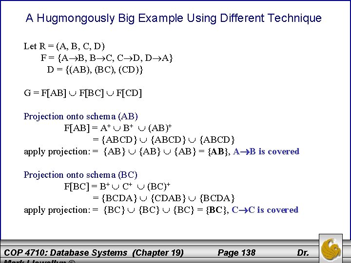
A Hugmongously Big Example Using Different Technique Let R = (A, B, C, D) F = {A B, B C, C D, D A} D = {(AB), (BC), (CD)} G = F[AB] F[BC] F[CD] Projection onto schema (AB) F[AB] = A+ B+ (AB)+ = {ABCD} apply projection: = {AB} = {AB}, A B is covered Projection onto schema (BC) F[BC] = B+ C+ (BC)+ = {BCDA} {CDAB} {BCDA} apply projection: = {BC} = {BC}, C C is covered COP 4710: Database Systems (Chapter 19) Page 138 Dr.
![A Hugmongously Big Example Using Different Technique (cont. ) Projection onto schema (CD) F[CD] A Hugmongously Big Example Using Different Technique (cont. ) Projection onto schema (CD) F[CD]](http://slidetodoc.com/presentation_image_h2/833665a6d6a9a19a8cac9d491d93e7c4/image-139.jpg)
A Hugmongously Big Example Using Different Technique (cont. ) Projection onto schema (CD) F[CD] = C+ D+ (CD)+ = {CDAB} {DABC} {CDAB} apply projection: = {CD} = {CD}, C D is covered • Thus, the projections have covered every functional dependency in F except D A. So, now the question becomes does G logically imply D A? • Generate D+(with respect to G) and if A is in this closure the answer is yes. Therefore, G ⊨ D A COP 4710: Database Systems (Chapter 19) Page 139 Dr.
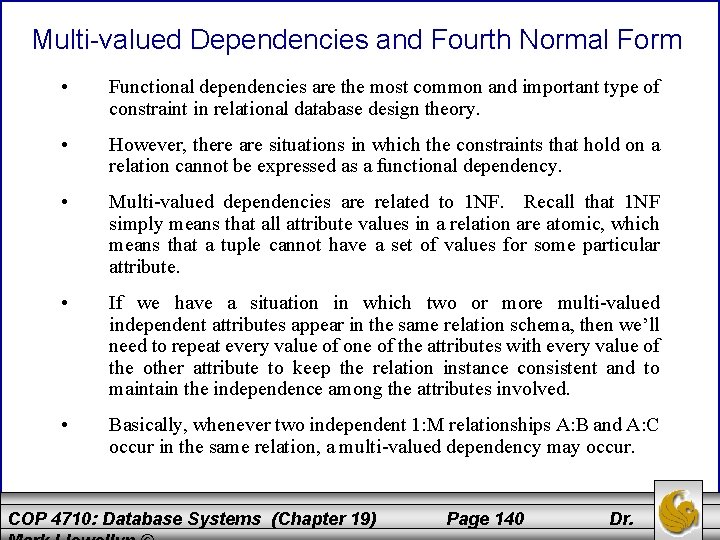
Multi-valued Dependencies and Fourth Normal Form • Functional dependencies are the most common and important type of constraint in relational database design theory. • However, there are situations in which the constraints that hold on a relation cannot be expressed as a functional dependency. • Multi-valued dependencies are related to 1 NF. Recall that 1 NF simply means that all attribute values in a relation are atomic, which means that a tuple cannot have a set of values for some particular attribute. • If we have a situation in which two or more multi-valued independent attributes appear in the same relation schema, then we’ll need to repeat every value of one of the attributes with every value of the other attribute to keep the relation instance consistent and to maintain the independence among the attributes involved. • Basically, whenever two independent 1: M relationships A: B and A: C occur in the same relation, a multi-valued dependency may occur. COP 4710: Database Systems (Chapter 19) Page 140 Dr.
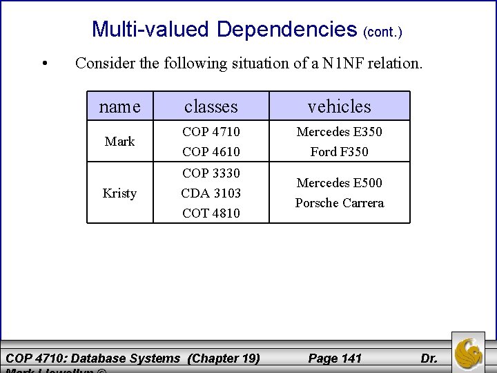
Multi-valued Dependencies (cont. ) • Consider the following situation of a N 1 NF relation. name classes vehicles Mark COP 4710 COP 4610 Mercedes E 350 Ford F 350 Kristy COP 3330 CDA 3103 COT 4810 Mercedes E 500 Porsche Carrera COP 4710: Database Systems (Chapter 19) Page 141 Dr.
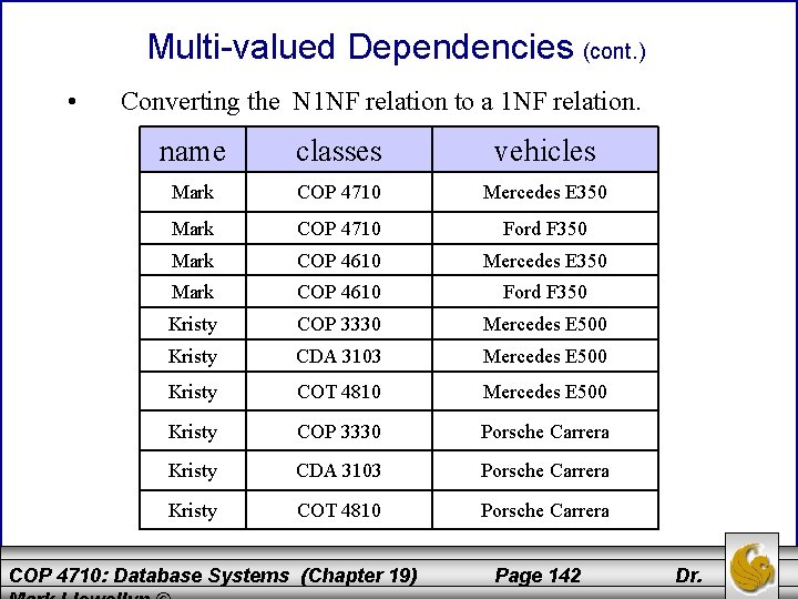
Multi-valued Dependencies (cont. ) • Converting the N 1 NF relation to a 1 NF relation. name classes vehicles Mark COP 4710 Mercedes E 350 Mark COP 4710 Ford F 350 Mark COP 4610 Mercedes E 350 Mark COP 4610 Ford F 350 Kristy COP 3330 Mercedes E 500 Kristy CDA 3103 Mercedes E 500 Kristy COT 4810 Mercedes E 500 Kristy COP 3330 Porsche Carrera Kristy CDA 3103 Porsche Carrera Kristy COT 4810 Porsche Carrera COP 4710: Database Systems (Chapter 19) Page 142 Dr.
Multi-valued Dependencies (cont. ) • Basically, a multi-valued dependency is an assertion that two attributes or sets of attributes are independent of one another. • This is a generalization of the notion of a functional dependency, in the sense that every fd implies a corresponding multi-valued dependency. • However, there are certain situations involving independence of attributes that cannot be explained as functional dependencies. • There are situations in which a relational schema may be in BCNF, yet the relation exhibits a kind of redundancy that is not related to functional dependencies. COP 4710: Database Systems (Chapter 19) Page 143 Dr.
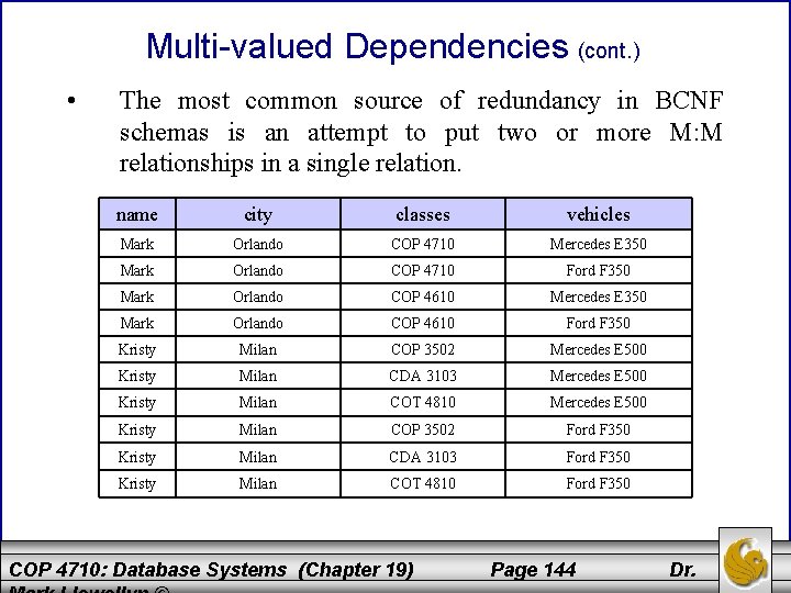
Multi-valued Dependencies (cont. ) • The most common source of redundancy in BCNF schemas is an attempt to put two or more M: M relationships in a single relation. name city classes vehicles Mark Orlando COP 4710 Mercedes E 350 Mark Orlando COP 4710 Ford F 350 Mark Orlando COP 4610 Mercedes E 350 Mark Orlando COP 4610 Ford F 350 Kristy Milan COP 3502 Mercedes E 500 Kristy Milan CDA 3103 Mercedes E 500 Kristy Milan COT 4810 Mercedes E 500 Kristy Milan COP 3502 Ford F 350 Kristy Milan CDA 3103 Ford F 350 Kristy Milan COT 4810 Ford F 350 COP 4710: Database Systems (Chapter 19) Page 144 Dr.

Multi-valued Dependencies (cont. ) • Focusing on the relation on the previous page, notice that there is no reason to associate a given class with a given vehicle and not another vehicle. • To express the fact that classes and vehicles are independent properties of a person, we have each class appear with each class. • Clearly, there is redundancy in this relation, but this relation does not violate BCNF. In fact there are no nontrivial functional dependencies at all in this schema. • We know from our earlier discussions of normal forms based on functional dependencies that redundancies were removed, yet here is a schema in BCNF that clearly contains redundant information. COP 4710: Database Systems (Chapter 19) Page 145 Dr.
Multi-valued Dependencies (cont. ) • For example, in this relation, attribute city is not functionally determined by any of the other three attributes. • Thus the fd: name class vehicle city does not hold for this schema because we could have two persons with the same name, enrolled in the same class, and drive the same type of vehicle. • You should verify that none of the four attributes in functionally determined by the other three. Which means that there are no non-trivial functional dependencies that hold on this relation schema. • Thus, all four attributes form the only key and this means that the relation is in BCNF, yet clearly is redundant. COP 4710: Database Systems (Chapter 19) Page 146 Dr.
Multi-valued Dependencies (cont. ) • A multi-valued dependency (mvd) is a statement about some relation R that when you fix the values for one set of attributes, then the values in certain other attributes are independent of the values of all the other attributes in the relation. • More precisely, we have the mvd A 1 A 2. . . An ↠ B 1 B 2. . . Bm holds for a relation R if when we restrict ourselves to the tuples of R that have particular values for each of the attributes among the A’s, then the set of values we find among the B’s is independent of the set of values we find among the attributes of R that are not among the A’s or B’s. COP 4710: Database Systems (Chapter 19) Page 147 Dr.
Multi-valued Dependencies (cont. ) • Even more precisely, a mvd holds if: For each pair of tuples t and u of relation R that agree on all the A’s, we can find in R some tuple v that agrees: 1. With both t and u on the A’s 2. With t on the B’s 3. With u on all attributes of R that are not among the A’s or B’s. – Note that we can use this rule with t and u interchanged, to infer the existence of a fourth tuple w that agrees with u on the B’s and with t on the other attributes. As a consequence, for any fixed values of the A’s, the associated values of the B’s and the other attributes appear in all possible combinations in different tuples. COP 4710: Database Systems (Chapter 19) Page 148 Dr.
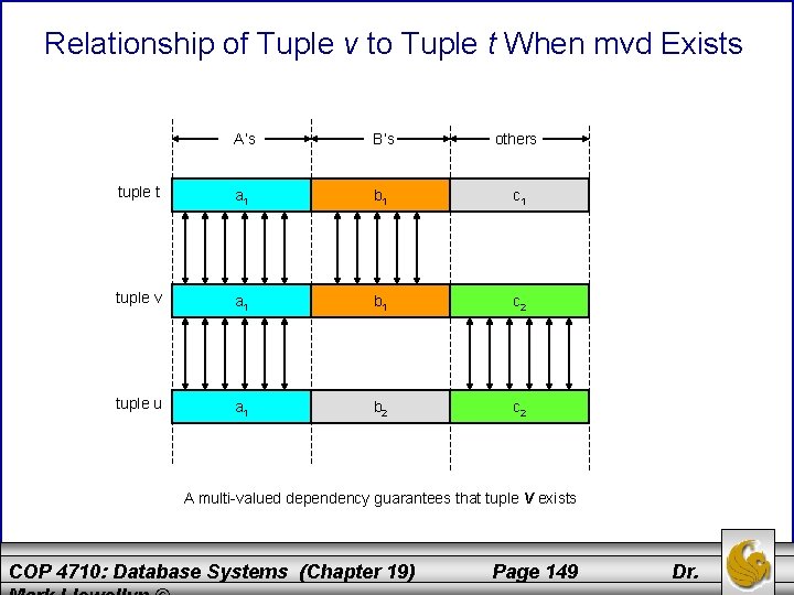
Relationship of Tuple v to Tuple t When mvd Exists A’s B’s others tuple t a 1 b 1 c 1 tuple v a 1 b 1 c 2 tuple u a 1 b 2 c 2 A multi-valued dependency guarantees that tuple v exists COP 4710: Database Systems (Chapter 19) Page 149 Dr.
Multi-valued Dependencies (cont. ) • In general, we can assume that the A’s and B’s (left side and right side) of a mvd are disjoint. • As with functional dependencies, it is permissible to add some of the A’s to the right side. • Unlike, functional dependencies where a set of attributes on the right side was a short-hand notation for a set of fds with single attribute right sides, with mvds, we must deal only with sets of attributes on the right side as it is not always possible to break the right side of mvds into single attributes. COP 4710: Database Systems (Chapter 19) Page 150 Dr.
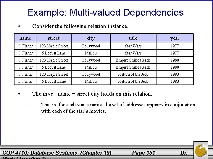
Example: Multi-valued Dependencies • Consider the following relation instance. name street city title year C. Fisher 123 Maple Street Hollywood Star Wars 1977 C. Fisher 5 Locust Lane Malibu Star Wars 1977 C. Fisher 123 Maple Street Hollywood Empire Strikes Back 1980 C. Fisher 5 Locust Lane Malibu Empire Strikes Back 1980 C. Fisher 123 Maple Street Hollywood Return of the Jedi 1983 C. Fisher 5 Locust Lane Malibu Return of the Jedi 1983 • The mvd name ↠ street city holds on this relation. – That is, for each star’s name, the set of addresses appears in conjunction with each of the star’s movies. COP 4710: Database Systems (Chapter 19) Page 151 Dr.
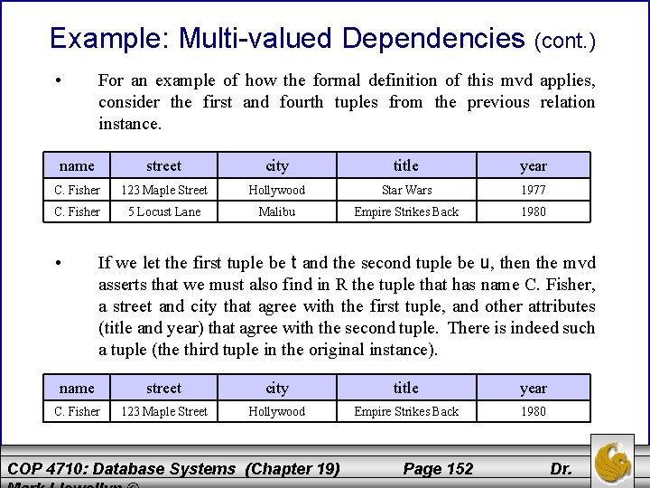
Example: Multi-valued Dependencies (cont. ) • For an example of how the formal definition of this mvd applies, consider the first and fourth tuples from the previous relation instance. name street city title year C. Fisher 123 Maple Street Hollywood Star Wars 1977 C. Fisher 5 Locust Lane Malibu Empire Strikes Back 1980 • If we let the first tuple be t and the second tuple be u, then the mvd asserts that we must also find in R the tuple that has name C. Fisher, a street and city that agree with the first tuple, and other attributes (title and year) that agree with the second tuple. There is indeed such a tuple (the third tuple in the original instance). name street city title year C. Fisher 123 Maple Street Hollywood Empire Strikes Back 1980 COP 4710: Database Systems (Chapter 19) Page 152 Dr.
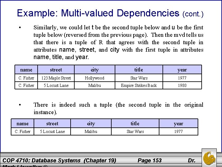
Example: Multi-valued Dependencies (cont. ) • Similarly, we could let t be the second tuple below and u be the first tuple below (reversed from the previous page). Then the mvd tells us that there is a tuple of R that agrees with the second tuple in attributes name, street, and city with the first tuple in attributes name, title, and year. name street city title year C. Fisher 123 Maple Street Hollywood Star Wars 1977 C. Fisher 5 Locust Lane Malibu Empire Strikes Back 1980 • There is indeed such a tuple (the second tuple in the original instance). name street city title year C. Fisher 5 Locust Lane Malibu Star Wars 1977 COP 4710: Database Systems (Chapter 19) Page 153 Dr.
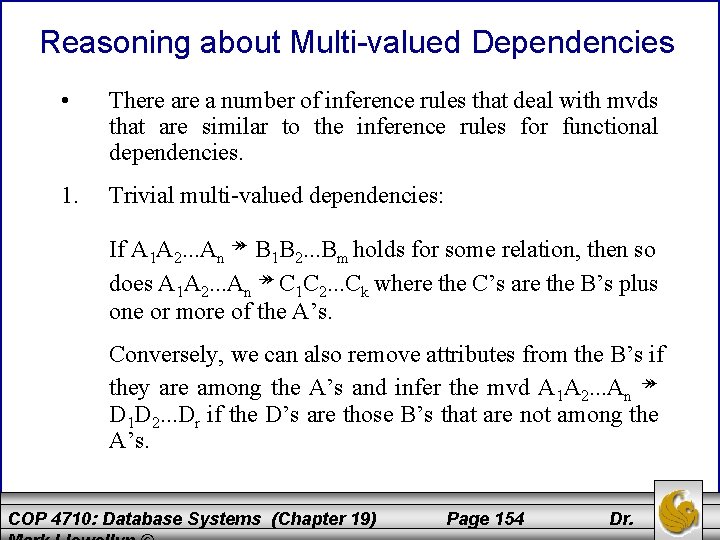
Reasoning about Multi-valued Dependencies • There a number of inference rules that deal with mvds that are similar to the inference rules for functional dependencies. 1. Trivial multi-valued dependencies: If A 1 A 2. . . An ↠ B 1 B 2. . . Bm holds for some relation, then so does A 1 A 2. . . An ↠ C 1 C 2. . . Ck where the C’s are the B’s plus one or more of the A’s. Conversely, we can also remove attributes from the B’s if they are among the A’s and infer the mvd A 1 A 2. . . An ↠ D 1 D 2. . . Dr if the D’s are those B’s that are not among the A’s. COP 4710: Database Systems (Chapter 19) Page 154 Dr.
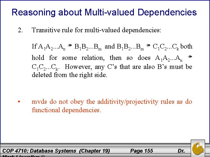
Reasoning about Multi-valued Dependencies 2. Transitive rule for multi-valued dependencies: If A 1 A 2. . . An ↠ B 1 B 2. . . Bm and B 1 B 2. . . Bm ↠ C 1 C 2. . . Ck both hold for some relation, then so does A 1 A 2. . . An ↠ C 1 C 2. . . Ck. However, any C’s that are also B’s must be deleted from the right side. • mvds do not obey the additivity/projectivity rules as do functional dependencies. COP 4710: Database Systems (Chapter 19) Page 155 Dr.
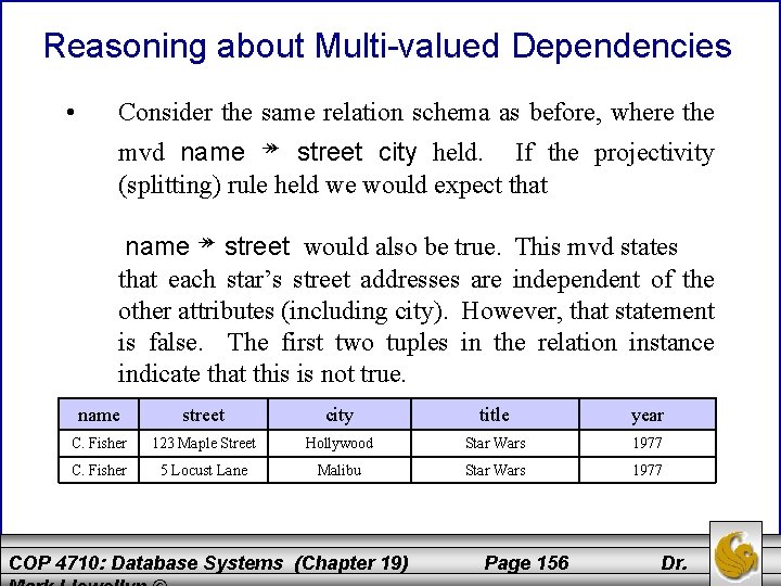
Reasoning about Multi-valued Dependencies • Consider the same relation schema as before, where the mvd name ↠ street city held. If the projectivity (splitting) rule held we would expect that name ↠ street would also be true. This mvd states that each star’s street addresses are independent of the other attributes (including city). However, that statement is false. The first two tuples in the relation instance indicate that this is not true. name street city title year C. Fisher 123 Maple Street Hollywood Star Wars 1977 C. Fisher 5 Locust Lane Malibu Star Wars 1977 COP 4710: Database Systems (Chapter 19) Page 156 Dr.
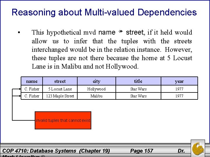
Reasoning about Multi-valued Dependencies • This hypothetical mvd name ↠ street, if it held would allow us to infer that the tuples with the streets interchanged would be in the relation instance. However, these tuples are not there because the home at 5 Locust Lane is in Malibu and not Hollywood. name street city title year C. Fisher 5 Locust Lane Hollywood Star Wars 1977 C. Fisher 123 Maple Street Malibu Star Wars 1977 invalid tuples that cannot exist COP 4710: Database Systems (Chapter 19) Page 157 Dr.
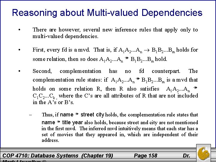
Reasoning about Multi-valued Dependencies • There are however, several new inference rules that apply only to multi-valued dependencies. • First, every fd is a mvd. That is, if A 1 A 2. . . An B 1 B 2. . . Bm holds for some relation, then so does A 1 A 2. . . An ↠ B 1 B 2. . . Bm hold. • Second, complementation has no fd counterpart. The complementation rule states: if A 1 A 2. . . An ↠ B 1 B 2. . . Bm is a mvd that holds on some relation R, then R also satisfies A 1 A 2. . . An ↠ C 1 C 2. . . Ck , where the C’s are all attributes of R that are not included in the A’s or B’s. – Thus, if name ↠ street city holds, the complementation rule states that name ↠ title year also holds, because street and city are not mentioned in the first mvd. The inferred mvd intuitively means that each star has a set of movies that they appeared in, which are independent of their address. COP 4710: Database Systems (Chapter 19) Page 158 Dr.
Fourth Normal Form • The redundancy that we’ve seen in the relation instances in this section of the notes are caused by the existence of multi-valued dependencies. • As we did with functional dependencies, we can use multi-valued dependencies and a different decomposition algorithm to produce a stronger normal form which is based not on functional dependencies but the multivalued dependencies. • Fourth Normal Form (4 NF) eliminates all non-trivial multi-valued dependencies (as are all fds that violate BCNF). The resulting decomposition scheme has neither the redundancy from fds nor redundancy from mvds. COP 4710: Database Systems (Chapter 19) Page 159 Dr.

Fourth Normal Form (cont. ) • A mvd A 1 A 2. . . An ↠ B 1 B 2. . . Bm for a relation scheme R is non-trivial if: 1. None of the B’s is among the A’s. 2. Not all of the attributes of R are among the A’s and B’s. • 4 NF is essentially the BCNF condition, but applied to mvds instead of fds. • Formally, a relation scheme R is in 4 NF if whenever A 1 A 2. . . An ↠ B 1 B 2. . . Bm is a non-trivial mvd, {A 1 A 2. . . An} is a superkey of R. COP 4710: Database Systems (Chapter 19) Page 160 Dr.
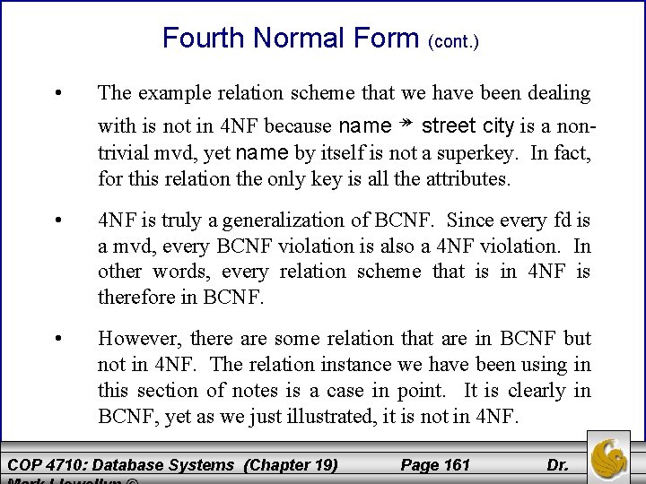
Fourth Normal Form (cont. ) • The example relation scheme that we have been dealing with is not in 4 NF because name ↠ street city is a nontrivial mvd, yet name by itself is not a superkey. In fact, for this relation the only key is all the attributes. • 4 NF is truly a generalization of BCNF. Since every fd is a mvd, every BCNF violation is also a 4 NF violation. In other words, every relation scheme that is in 4 NF is therefore in BCNF. • However, there are some relation that are in BCNF but not in 4 NF. The relation instance we have been using in this section of notes is a case in point. It is clearly in BCNF, yet as we just illustrated, it is not in 4 NF. COP 4710: Database Systems (Chapter 19) Page 161 Dr.

Decomposition into Fourth Normal Form • The 4 NF decomposition algorithm is analogous to the 3 NF and BCNF decomposition algorithm: • Find a 4 NF violation, say A 1 A 2. . . An ↠ B 1 B 2. . . Bm where {A 1 A 2. . . An} is not a superkey. Note that this mvd could be a true mvd or it could be derived from the corresponding fd A 1 A 2. . . An B 1 B 2. . . Bm , since every fd is an mvd. Then break the schema for R into two schemas where: (1) the first schema contains all the A’s and B’s and the second schema contains the A’s and all the attributes of R that are not among the A’s or B’s. COP 4710: Database Systems (Chapter 19) Page 162 Dr.
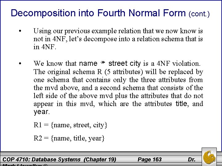
Decomposition into Fourth Normal Form (cont. ) • Using our previous example relation that we now know is not in 4 NF, let’s decompose into a relation schema that is in 4 NF. • We know that name ↠ street city is a 4 NF violation. The original schema R (5 attributes) will be replaced by one schema that contains only the three attributes from the mvd above, and a second schema that consists of the left side of the above mvd plus the attributes that do not appear in this mvd, which are the attributes title, and year. R 1 = {name, street, city} R 2 = {name, title, year} COP 4710: Database Systems (Chapter 19) Page 163 Dr.
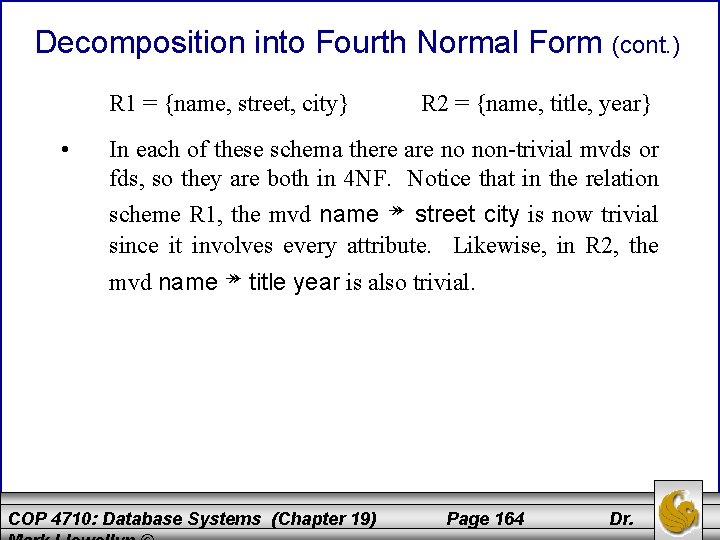
Decomposition into Fourth Normal Form (cont. ) R 1 = {name, street, city} • R 2 = {name, title, year} In each of these schema there are no non-trivial mvds or fds, so they are both in 4 NF. Notice that in the relation scheme R 1, the mvd name ↠ street city is now trivial since it involves every attribute. Likewise, in R 2, the mvd name ↠ title year is also trivial. COP 4710: Database Systems (Chapter 19) Page 164 Dr.
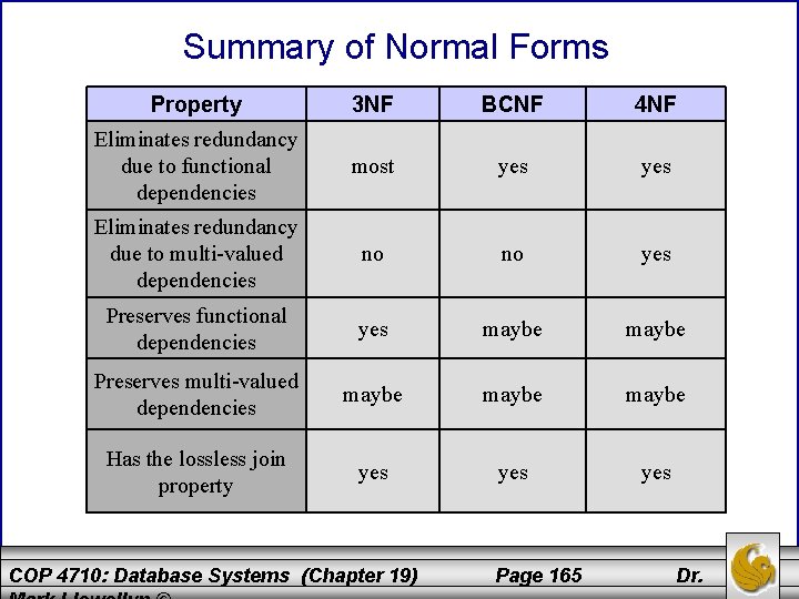
Summary of Normal Forms Property 3 NF BCNF 4 NF Eliminates redundancy due to functional dependencies most yes Eliminates redundancy due to multi-valued dependencies no no yes Preserves functional dependencies yes maybe Preserves multi-valued dependencies maybe Has the lossless join property yes yes COP 4710: Database Systems (Chapter 19) Page 165 Dr.
- Slides: 165
