CHAPTER 5 Metal Alloys Heat Treatment Phase Diagram


 Binary phase diagram (two")


 • This intermetallic compound is metastable,")


 DIAGRAM (Isothermal Transformation Diagram)")


- Slides: 58
CHAPTER 5 Metal Alloys: Heat Treatment, Phase Diagram and Phase Transformation
CO 3: Ability to explain and analyze the metal alloys microstructure, phase diagram, phase transformation and heat treatment processes.
Outline 1. 2. 3. 4. 5. Structure of Alloy Phase diagrams Phase transformations The Iron-Carbon System Heat Treatment of Ferrous alloys
Metal Alloys
METAL IN APPLICATIONS Aerospace Industry Automotive Shipping Manufactured Tool Steel Building constructions Offshore Platform 5 * All selected materials must be alloy designing! Technique to strengthen and harden metals is alloying
Aerospace 6
Automotive 7
8 Shipping manufactured
Tool Steel 9
10 Building constructions
11 Offshore Platform
Manufacturing Process of Metals
How to Enhance Mechanical Properties
Heat Treatment of Ferrous Alloys The various microstructures can be modified by heat treatment techniques i. e. by controlled heating and cooling of the alloys at various rates. This treatments induce phase transformations that greatly influence such mechanical properties as strength, hardness, ductility, toughness and wear resistance of the alloys.
Heat Treatment in Manufacturing
The heat treatment processes described as: 1. Annealing 2. Quenching 3. Tempering
ANNEALING § Is a general term used to describe heattreated with slowly cooling, primarily for softening of metallic material, to increase ductility and reduce hardness and strength, or so as to modify the microstructure § Annealing is also used to relieve residual stresses in a manufactured part, for the sake of improved machinability and of dimensional stability
Heat treatment process: Annealing The annealing process consists of the following steps : 1. heating the workpiece to a specific range temperature in a furnace; 2. holding it at that temperature for a period of time (soaking); and 3. air or furnace cooling.
QUENCHING § Involved with rapidly cooling to obtain special microstructure § Initially perform heating process and followed by subsequent immersion in quenching medium (water) § Phase transformation involves a sudden reorientation in material structure and thereby form a brittle and strong metal
Heat treatment process: Tempering § Should be tempered immediately after quenching § The steel is heated to a specific temperature, depending on composition, and then cooled at a prescribed rate. § Tempering reduce brittleness, to increase ductility and toughness, and to reduce residual stresses.
Hardenability of Ferrous Alloy The capability of an alloy to be hardened by heat treatment is called its hardenability. It is a measure of the depth of hardness that can be obtained by heating and subsequent quenching. Hardness • How much energy take to deform • The resistance of material to indentation • Depth of penetration under a large load • Rockwell hardness (diamond cone indenter)
Metal Alloys Alloying a metal is done by combining it with one or more other metals or non-metals that often improve its properties The term of alloy is used to describe a mixture of atom in which the primary constituent is a metal, called as base To describe alloys we have solute and solvent v Solute is the minor element that is added to the v solvent, which is the major element
Why need alloying? Provide a metallic substance with physical, mechanical and/or chemical properties and characteristics that are different from those of its components Alloy is chemically more stable than the component elements, so that alloys are designed for specific resistance to actions such as corrosion, wear and temperature.
Classification of Alloys Substitutional Alloys are where the metals combining have atoms of the same size Interstitial Alloys are where one of the alloying elements combining has atoms of smaller size. Carbon atoms are much smaller and fit into the gaps into the iron atoms
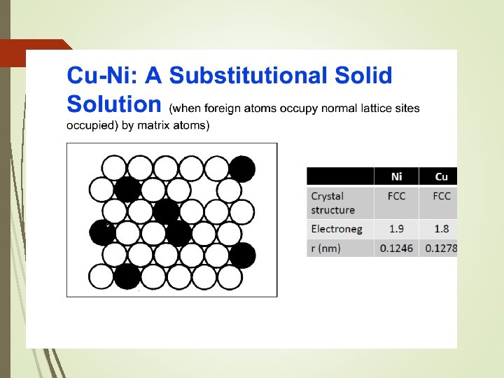
Structure of Alloys Substitutional Solid Solutions Solute atoms can replace solvent atoms and form a substitutional solid solution 2 conditions required to form complete substitutional solid solutions: § 2 metals must have similar crystal structures § Difference in their atomic radii should be less than 15%
Substitutional Solid Solution Atoms of the solvent elements are replaced in its unit cell by the dissolved element. Copper (solvent) Zinc (solute) dissolve
Zinc is dissolved in Copper to form Brass
Structure of Alloys Interstitial Solid Solutions Solute atom is smaller than solvent atom Each solute atom occupy an interstitial position; process form interstitial solid solution 2 conditions forming interstitial solutions: § Solvent atom have more than one valence electron § Solute atomic radius less than 59% of the solvent atom
Interstitial Solid Solution Atoms of the dissolving element fit into the vacant spaces between base metal atoms in the lattice structure. Iron (solvent) Carbon (solute) dissolve
Carbon is dissolved in Iron to form Steel
How are Metal Alloys made? The metals forming the alloys are melted in a furnace in a crucible. They are then poured into blocks called ingots and allowed to solidify. When a molten metal is mixed with another molten metal and allowed to solidify an alloy is formed. The new solid metal will have gone through ‘phase’ changes to become an alloy
Structure of Alloys Intermetallic Compound A compound of two or more metallic elements producing a new phase with its own composition, crystal structure and properties Consider as metal-metal system. For example, magnesium–lead system. The compound Mg 2 Pb has a composition of 19 wt. % Mg– 81 wt. % Pb
Intermetallic Compounds The type of atomic bond may range from metallic to ionic. Characteristics of intermetallic compounds : ü ü ü Strong Hard Brittle High melting points Low density Good oxidation resistance
Effect of Alloying Element on Steel Properties
Phase Diagrams Phase diagrams is significant to the engineer relates to the design and control of heat-treating procedures The understanding of phase diagrams for alloy systems is extremely important because there is a strong correlation between microstructure and mechanical properties
Phase Diagrams § § 8 -2 Represents phases present in metal at different conditions (Temperature, pressure and composition). Indicates equilibrium solid solubility of one element in another. Indicates temperature range under which solidification occurs. Indicates temperature at which different phases start to melt.
Thermal Equilibrium Diagram
Parts of Thermal Equilibrium Diagram Solidus Line - All points below this line are in solid form Liquidus Line - All points above this line are in liquid form Pasty Region - Between the solidus and liquidus lines, all points are in a mixture of liquid and solid form Liquid Region - The alloy is completely liquid in this region Solid Region - The alloy is completely solid in this region
Example : Phase diagram for nickel-copper alloy.
Classification of phase diagrams Unary phase diagram (single components system) Binary phase diagram (two components system) Tertiary phase diagram (three components system) Quarter phase diagram (four components system)
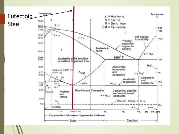
Iron Carbon System Phase Diagram • The arrangement can be modified by adding atoms of some other element, known Alloying • Normally, pure iron, upon heating experience two changes in crystal structure. The reason that metal form different crystal structure is to minimize the energy required to fit together in a regular pattern • In the simplest form, steels are alloys of Iron (Fe) and Carbon (C). The Fe-C phase diagram is a fairly complex one, but we will only consider the steel part of the diagram, up to around 7% Carbon.
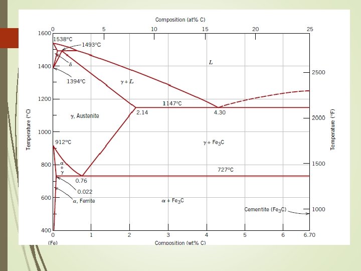
Phase diagram for iron-carbon system Pure iron melts at 1538⁰C As iron cools, it forms delta ferrite Austenite Alpha ferrite
The Iron–Carbon System • • • Ferrite Alpha ferrite denoted α-ferrite or ferrite It is a solid solution of bcc iron Delta ferrite (δ-ferrite) is stable only at very high temperatures and is of no practical significance in engineering • Ferrite is soft and ductile
Alpha Ferrite α-ferrite - solid solution of C in BCC Fe • Stable form of iron at room temperature. • The maximum solubility of C is 0. 022 wt% • Transforms to FCC γ-austenite at 912 °C
Delta Ferrite δ-ferrite solid solution of C in BCC Fe • The same structure as α-ferrite • Stable only at high T, above 1394 °C • Melts at 1538 °
The Iron–Carbon System Austenite • Within a certain temperature range, iron undergoes a polymorphic transformation from a bcc to a fcc structure, • Becomes gamma iron (γ-iron) or austenite • Austenite is denser than ferrite and important in heat treatment • Possesses good formability
Austenite γ-austenite - solid solution of C in FCC Fe • The maximum solubility of C is 2. 14 wt %. • Transforms to BCC δ-ferrite at 1395 °C • Is not stable below the eutectic temperature (727 ° C) unless cooled rapidly
The Iron–Carbon System Cementite • Right boundary represents cementite, also called carbide • Cementite is very hard and brittle intermetallic compound • Has a significant influence on the properties of steels
Cementite Fe 3 C (iron carbide or cementite) • This intermetallic compound is metastable, it remains as a compound indefinitely at room T, but decomposes into α-Fe and C (graphite) at 650 - 700 °C
Iron Carbon System Pure iron melts at 1538 o. C. Starting at room temperature the phase is alpha (a) or ferrite. At 912 o. C, ferrite transforms to gamma (g) or austenite. This, in turn, transforms at 1394 o. C to delta (d), which remains until melting occurs. The 3 phases are distinct : alpha has BCC structures gamma has FCC structures delta has BCC structures
Solubility limits of carbon in iron are low in the ferrite phase - only about 0. 022% at 723 o. C. Austenite can dissolve up to about 2. 1% carbon at a temperature of 1130 o. C.
TIME TEMPERATURE TRANSFORMATION (TTT) DIAGRAM (Isothermal Transformation Diagram)
Phase Diagram vs. TTT Diagram Phase Diagram TTT Diagram § Important information, useful § Practical information to gives in materials development the information of and selection transformation for different phases § It shows phases present at different compositions and § TTT diagram is plotted for temperatures different length of time and temperature § These diagrams do not indicate the dynamics when § With the help of TTT one phase transforms into diagram, we can control the another phase transformation by changing the conditions
TTT Diagram TTT diagram indicates the amount of transformation at a constant temperature TTT diagram is for the eutectoid carbon steel Austenite is stable above the A 1 temperature Below austenite is unstable. Thus, it can be transform into pearlite, bainite and martensite
Transformation involving austenite for Fe-C system