ENT 2493 ELECTRICAL CIRCUIT AND MACHINE 3 PHASE
")


 surrounded")

 Wye Connected Source b) Delta Connected Source")


: measured")


, Alexander, Sadiku, Mc. Graw. Hill.")
- Slides: 43
ENT 249/3 ELECTRICAL CIRCUIT AND MACHINE (3 -PHASE CIRCUITS)
CONTENTS • INTRODUCTION • BALANCED THREE-PHASE VOLTAGES • BALANCED WYE-WYE CONNECTION • BALANCED WYE-DELTA CONNECTION • BALANCED DELTA-WYE CONNECTION
INTRODUCTION 1. Single – phase ac power system consists of a generator connected through a pair of wires (transmission line ) to a load. Vp is the rms magnitude of voltage source Single-phase systems : a) two-wire type, b) three-wire type Contain with two identical sources (equal magnitude and same phase)
INTRODUCTION • Polyphase: circuits or systems in which the ac sources operate at the same frequency but different phases. Two-phase three-wire system. ØTwo phase system produced by a generator consisting of two coil placed perpendicular to each other. ØVoltage generated by one lags the other by 90 o. Three-phase four-wire system. ØThree-phase system produced by a generator consisting of 3 sources ( same magnitude & frequency but of phase with each other by 120 o).
INTRODUCTION In general, three-phase systems are preferred over singlephase systems for many reasons. 1. Nearly all electric power is generated and distributed in three– phase. 2. The instantaneous power in a three–phase system can be constant–results in uniform power transmission and less vibration (constant torque). 3. More economical than the single–phase. 4. The power delivery capacity tripled (increased by 200%) by increasing the number of conductors from 2 to 3 (increased by 50%)
BALANCED THREE-PHASE VOLTAGES 1. The three-phase generator has three induction coils placed 120° apart on the stator. 2. The three coils have an equal number of turns, the voltage induced across each coil will have the same peak value, shape and frequency.
BALANCED THREE-PHASE VOLTAGES 1. Three-phase voltages are often produced with a three– phase ac generator (or alternator) whose cross-sectional view as shown in Figure. A three-phase generator The generated voltages are 120 o apart from each other.
BALANCED THREE-PHASE VOLTAGES A basic generator : • Consists of rotating magnet (rotor) surrounded by a stationary winding (stator) • Three separate winding/ coils with terminal a-a’, b-b’ and c-c’ are physically placed 120° apart around the stator. • As the rotor rotates, its magnitude field cuts the flux from the three coils and induces voltages in the coils.
BALANCED THREE-PHASE VOLTAGES q Because the coils are placed 120° apart, the induced voltages in the coils are equal magnitude but of phase by 120 °. The generated voltages are 120° apart from each other
BALANCED THREE-PHASE VOLTAGES Typical three–phase system a) Wye Connected Source b) Delta Connected Source • From the above figure, the voltages Van, Vbn, Vcn are respectively between the lines a, b, c and the neutral line n. These voltages are called phase voltage. • If the voltage source have same amplitude and frequency ω and out of phase with each other by 120°, the voltages are said to be balanced.
BALANCED THREE-PHASE VOLTAGES q This implies that, Balanced phase voltages are equal in magnitude and are out of phase with each other by 120° Since three–phase voltages are 120 ° out of phase with each other, there are two possible phase sequence or combinations: q abc sequence or positive sequence q acb sequence or negative sequence
BALANCED THREE-PHASE VOLTAGES 1. abc sequence or positive sequence: Where, • Vp is the effective or rms value of the phase abc or positive sequence
BALANCED THREE-PHASE VOLTAGES 1. For negative sequence: acb or negative sequence The phase sequence is the time order in which the voltage pass through their respective maximum values. A balanced load is one in which the phase impedances are equal in magnitude and in phase.
BALANCED THREE-PHASE LOADS A Balanced load has equal impedances on all the phases Za a) A Y-connected load, b) a- ∆ connected load
BALANCED THREE-PHASE LOADS q For balanced wye – connected load, q For balanced delta – connected load, Za
THREE-PHASE CONNECTIONS Ø Both the three phase source and the three phase load can be connected either Wye or DELTA. Four possibilities connections: • Wye – wye (Y-Y) connection • Wye – delta (Y-∆)connection • Delta – delta (∆ - ∆) connection • Delta – wye (∆ -Y) connection • Balanced Δ connected load is more common. • Y connected sources are more common.
BALANCED WYE-WYE CONNECTION A balanced Y-Y system, showing the source, line and load impedances A balanced Y-Y system is a three-phase system with a balanced Yconnected source and a balance Y-connected load. Line Impedance Source Impedance Load Impedance
BALANCED WYE-WYE CONNECTION Four main elements in three–phase circuit: q Phase Voltage (VØ): measured between the neutral and any line , i. e line to neutral voltage. q Line Voltage (VL): measured between two of the three lines, i. e line to line voltage. q Line current (IL): current in each line of the source or load. q Phase current (IØ): current in each phase of the source or load.
BALANCED WYE-WYE CONNECTION A balanced Y-Y system Line current In add up to zero. Neutral current is zero: In= -(Ia+ Ib+ Ic)= 0 • Phase voltages are: Van, Vbn and Vcn. • The three conductors connected from a to A, b to B and c to C are called LINES. • The voltage from one line to another is called a LINE voltage • Line voltages are: Vab, Vbc and Vca • Magnitude of line voltages is √ 3 times the magnitude of phase voltages. VL= √ 3 Vp
BALANCED WYE-WYE CONNECTION Line current In add up to zero. Neutral current is zero: In= -(Ia+ Ib+ Ic)= 0 Line voltage Ø Magnitude of line voltages is √ 3 times the magnitude of phase voltages. VL= √ 3 Vp
BALANCED WYE-WYE CONNECTION Phasor diagrams illustrating the relationship between line voltages and phase voltages
SINGLE PHASE EQUIVALENT OF BALANCED Y-Y CONNECTION • Balanced three phase circuits can be analyzed on “per phase “ basis. . (single phase analysis) • We look at one phase, say phase a and analyze the single phase equivalent circuit. • Because the circuit is balanced, we can easily obtain other phase values using their phase relationships.
BALANCED WYE-WYE CONNECTION SUMMARY • Phase and line voltages/ currents for balanced Y-Y system (assuming positive/ abc sequence): Phase voltages/currents Line voltages/ currents
EXAMPLE 1 A Y-connected balanced three-phase generator with an impedance of 0. 4+j 0. 3 Ω per phase is connected to a Yconnected balanced load with an impedance of 24+j 19 Ω per phase. The line joining the generator and the load has an impedance of 0. 6+j 0. 7 Ω per phase. Assuming a positive sequence for the source voltages and that Van=120 30° V. Find: 1. The line voltage 2. The line currents
solution
EXercise 1 A balanced three-phase generator has an abc phase sequence with phase voltage Van = 255∠ 0 o V. The generator feeds an induction motor which may represented by a balanced Y-connected load with an impedance of 12+j 5 Ω per phase. Assume a line impedance is 2Ω per phase. Calculate: 1. The line currents 2. The voltage for each load
BALANCED WYE-DELTA CONNECTION A balanced Y – ∆ system consists of a balanced Y-connected source feeding a balanced ∆ -connected load. • Three phase sources are usually Wye connected and three phase loads are Delta connected. • There is no neutral connection for the Y-∆ system. Phase current
BALANCED WYE-DELTA CONNECTION Line currents are obtained from the phase currents IAB, IBC and ICA
BALANCED WYE-DELTA CONNECTION • Assuming positive sequence, the phase voltage again: From previous section, the line voltage are The line voltages are equal to the voltages across the load impedances
BALANCED WYE-DELTA CONNECTION Phasor diagram illustrating the relationship between phase and line currents. Single phase equivalent circuit of the balanced Wye-delta connection
BALANCED WYE-DELTA CONNECTION SUMMARY • Phase and line voltages/ currents for balanced Y-∆ system (assuming positive/ abc sequence) Phase voltages/currents Line voltages/ currents
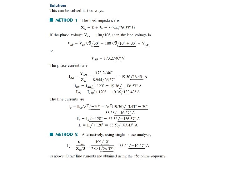
EXAMPLE 2 A balanced abc sequence Y – connected source with Van = 100∠ 10 o V is connected to a ∆ - connected balanced load 8+j 4 Ω per phase. i. Draw the 3 -phase circuit ii. Calculate phase and line currents.
BALANCED DELTA-DELTA CONNECTION A balanced ∆- ∆ system is one which both the balanced source and balanced load are ∆-connected. • Both the source and load are Delta connected and balanced
BALANCED DELTA-DELTA CONNECTION SUMMARY • Phase and line voltages/ currents for balanced ∆ -∆ system (assuming positive/ abc sequence) Phase voltages/currents Line voltages/ currents
EXERCISE 2
BALANCED DELTA-WYE CONNECTION A balanced ∆- Y system consists of balanced ∆-connected source feeding a balanced Y-connected load.
BALANCED DELTA-WYE CONNECTION Transforming a Delta connected source to an equivalent Wye connection Single phase equivalent of Delta Wye connection
BALANCED DELTA-WYE CONNECTION SUMMARY • Phase and line voltages/ currents for balanced ∆ -Y system (assuming positive/ abc sequence) Phase voltages/currents Line voltages/ currents
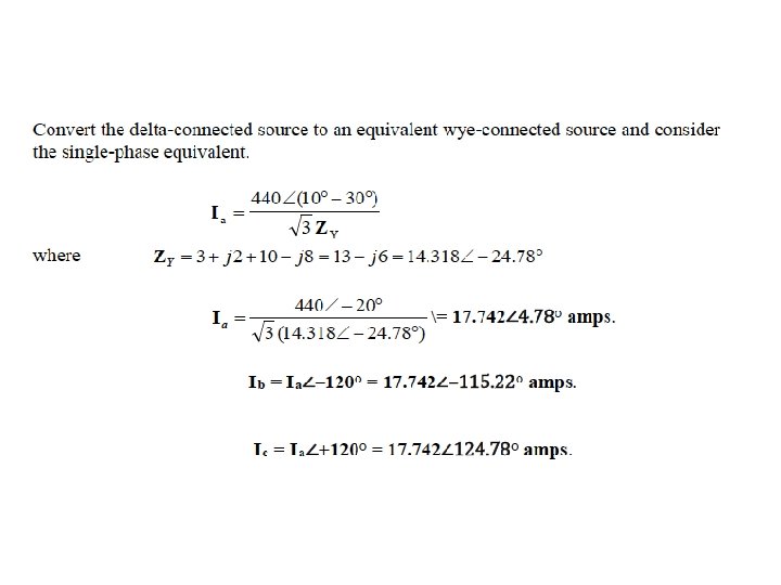
EXAMPLE 3 In a balance ∆-Y connected circuit, Vab=440 ∠ 15 o V and Zy= 12+j 15Ω. i. Draw the circuit ii. Calculate the line currents.
EXERCISE 3 In a balance ∆-Y connected circuit, if Vab=440 ∠ 10 o V, Vbc=440 ∠-110 o V and Vca=440 ∠ 130 o V, calculate the line currents.
FURTHER READING… Fundamentals of electric circuit. (6 th Edition), Alexander, Sadiku, Mc. Graw. Hill. (chapter 12). Electric circuits. 8 th edition, Nilsson &Riedel, Pearson. (chapter 11).