CHANNEL CODING Introduction The purpose of channel coding


 are unchanged")
 to choose the number")
![Notes: 1 -A linear code can correct t=Int[(HD-1)/2] of random (isolated) errors and detect](https://slidetodoc.com/presentation_image_h2/f85790fcc979b7b216f4d243b698f2f3/image-8.jpg "Notes: 1 -A linear code can correct t=Int[(HD-1)/2] of random (isolated) errors and detect")
 Hamming code with")
=3=HD, i. e. t= int(3 -1)/2=1 bit. Hence, this is a single error")

![Depending on t not all of these errors can be corrected. If [R] is](https://slidetodoc.com/presentation_image_h2/f85790fcc979b7b216f4d243b698f2f3/image-13.jpg "Depending on t not all of these errors can be corrected. If [R] is")
![The parity check matrix [H] must satisfy the following: No all zero columns so](https://slidetodoc.com/presentation_image_h2/f85790fcc979b7b216f4d243b698f2f3/image-14.jpg "The parity check matrix [H] must satisfy the following: No all zero columns so")
![If the received word is [R]=[1001111] then, [S]= which is similar to the 4](https://slidetodoc.com/presentation_image_h2/f85790fcc979b7b216f4d243b698f2f3/image-15.jpg "If the received word is [R]=[1001111] then, [S]= which is similar to the 4")


![GENERATION OF CYCLIC CODES: A)NONSYSTEMATIC CYCLIC CODES: (MULTIPLICATIVE ): Procedure: (1) For [D]=[a 1](https://slidetodoc.com/presentation_image_h2/f85790fcc979b7b216f4d243b698f2f3/image-21.jpg "GENERATION OF CYCLIC CODES: A)NONSYSTEMATIC CYCLIC CODES: (MULTIPLICATIVE ): Procedure: (1) For [D]=[a 1")
 Multiply D(x) by what is called generator polynomial g(x) of order r=n-k. This")
= x 3+x 2+1 or g")
 nonsystematic cyclic code with")
 SYSTEMATIC CYCLIC CODES (DIVISION): The procedure for the generation of (n, k) systematic")
")


![For [D]=[0101] with always zero initial states, then Then c 1 c 2 c](https://slidetodoc.com/presentation_image_h2/f85790fcc979b7b216f4d243b698f2f3/image-33.jpg "For [D]=[0101] with always zero initial states, then Then c 1 c 2 c")
![Decoding of systematic cyclic code: At the receiver [R]=[C]+[E] where: [R] is the received](https://slidetodoc.com/presentation_image_h2/f85790fcc979b7b216f4d243b698f2f3/image-34.jpg "Decoding of systematic cyclic code: At the receiver [R]=[C]+[E] where: [R] is the received")
 systematic cyclic code with g(x)=x")
![Ex: Using previous syndrome table, find the corrected word for the received word [R]=[1011001].](https://slidetodoc.com/presentation_image_h2/f85790fcc979b7b216f4d243b698f2f3/image-36.jpg "Ex: Using previous syndrome table, find the corrected word for the received word [R]=[1011001].")
 by g(x) to obtain")
![Solution: Above circuit will be as shown for g(x)=x 3+x 2+1. Then [s]=[s 1](https://slidetodoc.com/presentation_image_h2/f85790fcc979b7b216f4d243b698f2f3/image-38.jpg "Solution: Above circuit will be as shown for g(x)=x 3+x 2+1. Then [s]=[s 1")

- Slides: 39
CHANNEL CODING Introduction: The purpose of channel coding is 1 -either to protect information from channel noise, distortion and jamming, which is the subject of error detecting and correcting codes. Or, 2 -to protect information from the 3 rd party (enemy) which is the subject of encryption, scrambling. In this course, only error detecting and correcting codes are discussed.
ERROR DETECTING AND CORRECTING CODES Concept: The basic idea behind error detecting or correcting codes is to add extra bits (or digits) to the information such that the receiver can use it to detect or correct errors with limited capabilities. These extra redundant bits are called parity or check or correction bits. So, if for each k digits, r parity digits are added then, the transmitted k+r=n digits will have r redundant digits and the code is called (n, k) code with code efficiency or rate of (k/n). In general, the ability of detection or correction depends on the techniques used and the n, k parameters.
ERROR DETECTING CODES Simple error detecting codes: The simplest error detection schemes are the well- known even and odd parity generators. For even parity, an extra bit is added for each k information bits such that the total number of 1’s is even. At the receiver, an error is detected if the number of 1’s is odd. However, if the number of 1’s is even, then either no error occurs or even number of errors occur. Hence: probability(detecting errors)=probability(odd number of errors) and : probability. (undetected errors)=probability(even number of errors). The same idea can be applied when number of 1’s is adjusted to be odd. The code rate (efficiency) is k/(k+1). To implement these parity generators, simple Ex-OR gates are used at TX and RX as shown below:
EX-OR gate k+1 rece. Bits i if ‘ 0’ no error is detected if‘ 1’ error is detected Hence, we can conclude that error detection is not ideal. It does not detect errors with 100% probability , since even number of errors behaves exactly the same as no error. Example: for even parity check code, if K=7 and bit error probability (bit error rate BER) is 10 -3 , find the prob. of detected and undetected errors. Note that, although the code used for detection is so simple (few EX-OR gates) but still we have big advantage since probability of detecting errors is much higher than probability of undetected errors. The advantage of error detection is clear when used together with ARQ (Automatic Repeat Query) systems. In these systems, two channels are used, the usual forward channel with error detection and a backward channel. Data are transmitted through the forward channel. These data are protected against errors with parity error detection. If the receiver detects errors then a backward channel will be used to inform the transmitter to retransmit(repeat) the same data so that in the next transmission, data is received correctly since errors occur randomly (may occur or may not occur).
Error Correcting Codes In order to make the receiver have the ability to detect and correct errors, then not only a single parity bit is used, but in stead r bits are used giving what is called the (n, k) code. Error Correcting Codes Block Codes Convolutional Codes
Basic definitions: 1 -systematic and nonsystematic codes: If information bits ( a’s) are unchanged in their values and positions at the transmitted codeword, then this code is said to be systematic. Input data [D]=[a 1 a 2 a 3 ……. ak], Output systematic (n, k) codeword is [C]=[ a 1 a 2 a 3 ……. ak c 1 c 2 c 3 ……. cr] However if data bits are spread or changed at the output codeword then, the code is said to be nonsystematic: Output nonsystematic(7, 4) codeword is [C]=[c 2 a 1 c 3 a 2 c 1 a 4 a 3] 2 - Hamming distance: it is the number of differences between corresponding bits and the ability of error detection and correction codes depends on this parameter. The Hamming distance between two codewords Ci and Cj is denoted by dij which is the number of bits that differ. For a binary (n, k) code with 2 k possible codewords then the minimum Hamming distance (HD) is the min(dij). Of course n dij 0. Example: Find the Hamming distance between the two codewords: [C 2]=[1011001]. Solution: Here, the no. of bits that differ is 2, hence d 12=2. [C 1]=[1011100] and Example: Find the minimum Hamming distance for the 3 codewords: [C 1]=[1011100], [C 2]=[1011001] [C 3]=[1011000]. Solution: Here d 12=2, d 13=1 and d 23=1. Hence min(dij)=1=(HD). Note that the calculation of HD becomes more difficult if no of codewords increases. 3 -Hamming weight: This is the number of 1’s in the non zero codeward Ci. It is denoted by i. As will be shown later, and for linear codes, min=HD=min(dij). This simplifies the calculation of HD. As an example, if [C 1]=[1011000], then 1=3, and for [C 2]=[0001010], then 2=2, and so on. 4 -Linear and nonlinear codes: when the r parity bits are obtained from a linear function of the k information bits then the code is said to be linear, otherwise it is a nonlinear code.
Hamming Bound: The purpose of Hamming bound is either 1) to choose the number of parity bits ( r) so that a certain error correction capability is obtained. Or 2) to find the error correction capability (t) if the number of parity bits (r ) is known For binary codes, this is given by: 2 n-k = 2 r where t is the number of bits to be corrected. Example: for a single correction code with k=4 find the no. of parity bits that should be added. . This gives 2 r 1+(4+r) and the minimum r is r=3 ( take minimum r to have max code efficiency). This is the (7, 4) code. the code is said to be perfect code. Perfect code: in Hamming bound , if the equality is satisfied then this code is said to be a perfect code. Example if k=5 and up to 3 errors are to be corrected, find the no. of check bits that should be added. : that gives: 2 r 1+(5+r)(4+r)/2+(5+r)(4+r)(3+r)/6, then min r here is r=9, and the code is the (14, 5) non perfect code(equal sign is not satisfied ). Note: If the (n, k) codewords are trans. through a channel having error prob=pe, then prob. of decoding a correct word at the Rx for t-error correcting code will be: P(correct words)=p(no error)+p(1 error)+……. . p(t errors) and prob(erroneous word)=1 -P(correct word). Hamming code: The first example given above is the Hamming code. It is a single error correcting perfect code with the following parameters: n=2 r-1, HD=3, t=1. The (7, 4), (15, 11), (31, 26) …. . are examples of Hamming codes are encoded and decoded as a linear block codes.
Notes: 1 -A linear code can correct t=Int[(HD-1)/2] of random (isolated) errors and detect (HD-1) random(isolated errors). 2 - HD is the min Hamming distance= min Linear Block Codes: Only systematic binary codes will be described. The r parity bits are obtained using a linear function of the a’s data. Mathematically, this can be described by the set of equations: C 1=h 11 a 1+h 12 a 2+h 13 a 3+……. . +h 1 kak C 2=h 21 a 1+h 22 a 2+h 23 a 3+……. . +h 2 kak …………………. . Cr=hr 1 a 1+hr 2 a 2+hr 3 a 3 +……. +hrkak ……………. . (1) Where + is mod-2 addition (EX-OR), product is the AND multiplication and hij coefficients are binary variables for a binary coding. The complete output codeword can be written in matrix form as: [C]= [D][G] ………(1) , where: = [ Ik : Pkxr ] which is kxn matrix. This matrix is called the generator matrix of the linear block code (LBC). Equation(1) can also be written in matrix form as: [ H ] [C] T=[0] ……………(2) where: [C]=[ a 1 a 2 a 3 ……. ak c 1 c 2 c 3 ……. cr] and [ H ] matrix is in fact related with [G] matrix by: [ H ]=[-PT : Ir], and for binary coding this – sign drops out. This rxn [H] matrix is called the parity check matrix. As will be shown, encoding can be done either using eq(1) ( [G] matrix ) or eq(2) ([H] matrix), but decoding is done using [H] matrix only.
Encoding of Linear Block codes: Example: a given binary (7, 4) Hamming code with a parity check matrix: , find: 1) encoder circuit 2) all possible codewords 3) error correction capability. Solution : using eq(2), [H][C]T=[0] will give: C 1=a 1+a 3+a 4, C 2=a 1+a 2+a 4, C 3=a 1+a 2+ a 3.
i(min)=3=HD, i. e. t= int(3 -1)/2=1 bit. Hence, this is a single error correcting code( Hamming code).
Example: Find the generator matrix for the previous LBC. Solution: r=3 , k=4 , n=7 ; [C]=[D][G]=[a 1 a 2 a 3 a 4 ] Note that the equation [C]=[D][G] gives: [C]=[a 1 a 2 a 3 a 4 (a 1+a 3+a 4) (a 1+a 2+a 3)]=[ a 1 a 2 a 3 a 4 c 1 c 2 c 3] as obtained before.
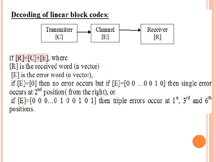
Depending on t not all of these errors can be corrected. If [R] is multiplied by [H] ( the receiver must know [H] ) then: [H] [R]T=[H][C]T+ [H] [E]T= [H][E]T since [H][C]T is set to [0] at the TX. Then define [S] vector : [S]=[H] [R]T= [H][E]T ……………. . (3) This [S] r-vector is called the syndrome. If [S]=[0], the RX decides on no error but if [S] [0], then the receiver must use [S] to find [E] and hence the corrected [C]=[R]+[E] Simple decoding procedure for single error: For single error Hamming codes, above mathematical solution is reduced into comparing the [S] r-vector with all columns of the [H] matrix (2 r-1 non zero and non repeated columns). That column similar to [S] is the position of error.
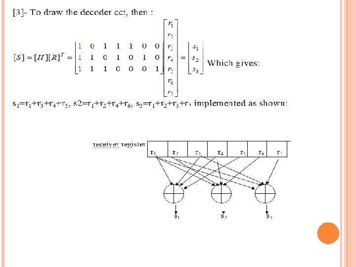
The parity check matrix [H] must satisfy the following: No all zero columns so as not to mix with the no error case. No repeated columns so that the decoder can decode any received word correctly with single error assumption Example: For previous example, [1]-Find the corrected word at the receiver, for the previous example, if the received word [R]=[1001111]. [2]-Find the syndrome vector if double errors occur at 1 st and last positions, comment. [3]Draw the decoder cct used to find the syndrome vector[S]. Solution: the parity check matrix is:
If the received word is [R]=[1001111] then, [S]= which is similar to the 4 th column in [H] Hence the corrected word [C]=[R]+ [E]=[1001111]+[0001000]= [1 0 0 0 1 1 1] [2]-To find the syndrome vector[S] for double errors, then [S]=[H][E]T. Where [E]=[1000001] corresponding to double errors at 1 st and last positions. Then:
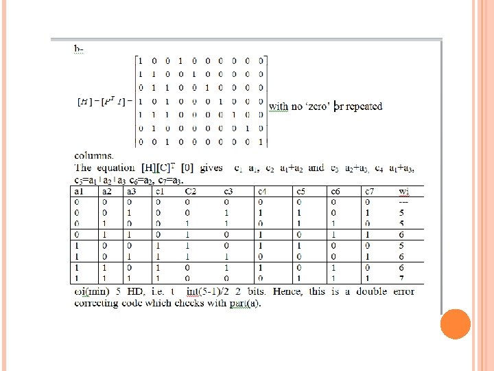
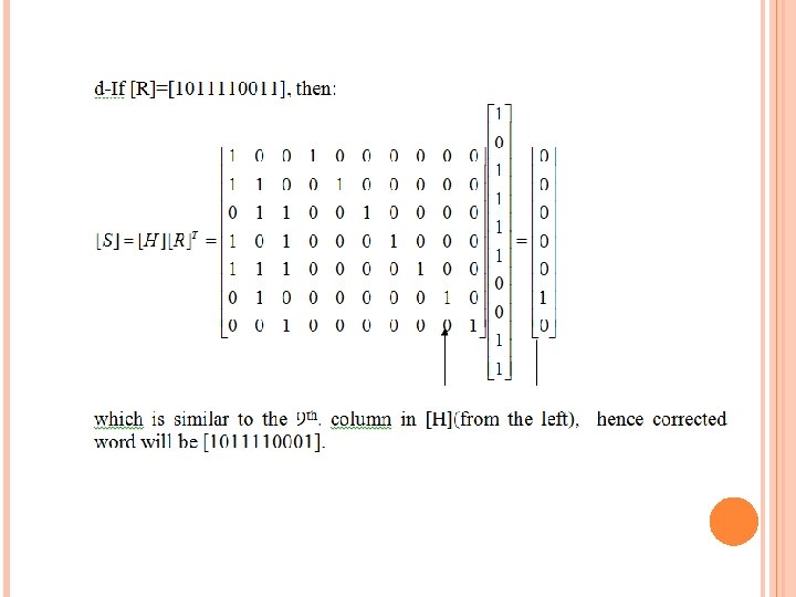
Example: The generator matrix of a LBC is given by: a-Use Hamming bound to find error correction capability. b-Find the parity check matrix. c-find the code table, Hamming weight and the error correction capability then compare with part(a). d-If the received word is [R]=[1011110011], find the corrected word at the Rx. Solution: (a) n=10, k=3, r=7 , (10, 3) code. Using Hamming bound, then: that gives 128>1+10+(10*9/2), i. e t=2 double error correction.
CYCLIC CODES These are subclass from the linear block codes. The name cyclic comes from the fact that any cyclic shift of a codeword is another codeword. i. e, if [C 1]=[0011010] is a codeword then [C 2]=[0001101] is another codeword obtained from [C 1] by a right circular shift. Cyclic codes can be classified into two types: Nonsystematic cyclic codes Systematic cyclic codes
GENERATION OF CYCLIC CODES: A)NONSYSTEMATIC CYCLIC CODES: (MULTIPLICATIVE ): Procedure: (1) For [D]=[a 1 a 2 …. . ak] data word, write the data word in terms of a power of a dummy variable x with a 1 weighted as MSB (Most Significant Bit) and ak as LSB(Least Significant Bit). a 1 MSB a 2 ……. ak-2 ak-1 ak LSB D(x)=ak+ak-1 x+ak-2 x 2+……. +a 2 xk-2+ a 1 xk-1 where ''+'' sign is mod-2 addition(Ex. OR) For example if [D]=[1 1 1 0 1], then D(x)=1+x 2+x 3+x 4 and if D(x)= x 6+x 2+1 then [D]=[1000101]
2) Multiply D(x) by what is called generator polynomial g(x) of order r=n-k. This g(x) is one or the multiplication of some factors of xn+1.
for n=7, r=3, we can choose either g 1(x)= x 3+x 2+1 or g 2(x)= x 3+x+1 for n=7, r=4, we can choose either g 1(x)=(x+1)(x 3+x 2+1) or g 2(x) =(x+1)(x 3+x+1) (3) The output codeword polynomial will be: C(x)=D(x) g(x) from which we can find the output codeword [C]
Ex: Write down the code table for the (7, 4) nonsystematic cyclic code with generator polynomial g(x)=x 3+x+1. Solution: Here n=7, k=4, r=3, [D]=[a 1 a 2 a 3 a 4], so the table has 16 rows starts from 0000 up to 1111 --if [D]=[0 0 0 1], then D(x)=1 and C(x)=D(x)g(x)=1*(x 3+x+1 ) then [C]=[0001011] --if [D]=[0 0 1 0], then D(x)=x and C(x)=D(x)g(x)=x(x 3+x+1)=x 4+x 2+x or [C]=[0010110]. --if [D]=[0011], then D(x)=1+x and C(x)=D(x)g(x)=(1+x)(x 3+x+1)=x 3+x+1+x 4+x 2+x=x 4+x 3+x 2+1 or [C]=[0011101] --if [D]=[0100], then D(x)=x 2 and C(x)=D(x)g(x)=x 2 (x 3+x+1)=x 5+x 3+x 2 or [C]=[0101100].
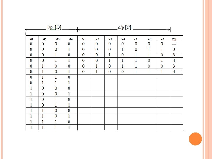
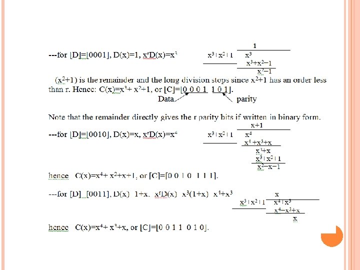
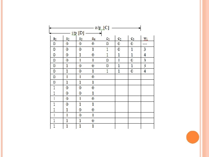
B) SYSTEMATIC CYCLIC CODES (DIVISION): The procedure for the generation of (n, k) systematic cyclic code is as follows: (1) Find D(x) from [D] as before. (2) As before, select a generator polynomial g(x) of order r from the factorization table of xn+1. (3)The output codeword will be: where Rem is the remainder of the long division of xr D(x) by g(x). (4) Use C(x) to find [C]. Ex: Write down the code table for the (7, 4) systematic cyclic code generated by the generator polynomial g(x)=x 3+x 2+1. Solution: Here n=7, k=4, r=3:
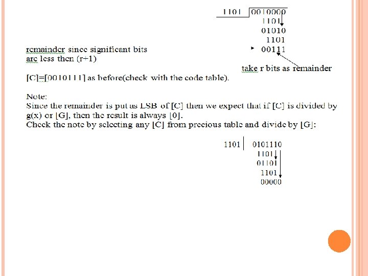
Note: Previous encoding procedure can also be done faster without polynomial representation if g(x) is converted to binary form called the divisor of the cyclic code. For example if g(x)=x 3+x 2+1, then the divisor [G]=[1101] consisting of (r+1) bits. Next to find [C] for [D]=[a 1 a 2 ……. ak], then put r 0's as LSB to get [a 1 a 2 ……. ak 0 0 0 … 0], then divide this by [G]. r 0's Ex: Using the generator polynomial of previous example, then g(x)=x 3+x 2+1 and [G]=[1101]. For [D]=[0011], then divide [0011000] by [1101]:
Implementation of systematic cyclic encoder: Practically, the previous long division required in long division is done using logic circuit that implements the division by g(x). In general, if: g(x)=go+g 1 x +g 2 x 2+………+gr xr, then we must note that for any factorization of xn+1, go=gr=1 always, hence only g 1, g 2, …. gr-1 is shown in the implementation The circuit in Figure below is build by connecting together three types of components: D-flip-flops, adders, and constant multipliers. 2 1 Switch S at position (1) and at the same time the control Z is enabled (Z=1) for k clock pulses. Then Z is disabled (Z=0) and switch S is changed to position (2) for r clock pulses.
Ex: Using the encoder circuit, find the output codeword for systematic cyclic code with g(x)=x 3+x 2+1 for data words [D]=[0101] and [0010]. Solution: 1) r=3, we need 3 flip flops g 1=0, g 2=1 2) we write the transition eqs for c 3, c 2, and c 1: For [D]=[0101] with always zero initial states, then
For [D]=[0101] with always zero initial states, then Then c 1 c 2 c 3=110 and [C]=[0101110] For [D]=[0010] K bits r bits Then c 1 c 2 c 3=111 and [C]=[0010111] K bits r bits
Decoding of systematic cyclic code: At the receiver [R]=[C]+[E] where: [R] is the received codeword [C] is the transmitted codeword; [E] is the error word writing above in polynomial form: Dividing both sides by g(x) taking the remainder, then: 1 - if s(x)=0, then the receiver decides on no error. 2 -if s(x)≠ 0, then errors occur. To find the location(s) of errors, the receiver may prepare a syndrome table and store it in its memory as a look up table, use it to find [E] from [s]. This look up syndrome table starts with most probable errors(less no of errors).
Ex: Prepare the syndrome table for the (7, 4) systematic cyclic code with g(x)=x 3+x 2+1 for single error. Solution: [G]=[1101]. Each [s] is found from [E] by using the equation For example if [E]=[0100000] which corresponds to a single error at the 2 nd position from the left, then: Hence [s]=[011], and so on. Note 1)no repeated syndromes are observed for single error. 2)when you start to find the syndromes for double error the syndrome will be similar to the syndrome for single error case(because t=1)
Ex: Using previous syndrome table, find the corrected word for the received word [R]=[1011001]. Solution: we find the syndrome from the equation below hence, [s]=[101], using previous syndrome table and for [s]=[101], then for single error [E]=[0001000], i. e. a single error at the 4 th position from the left. Hence corrected word=[R]+[E] =[1011001]+[0001000]= [1010001].
Implementation of systematic cyclic decoder: The long division of R(x) by g(x) to obtain the remainder is implemented using a modular feedback shift register as shown. The control Z is set (Z=1) for n clock pulses and reset (Z=0) for r clock pulses. Ex: Use the decoder circuit to find the syndrome and hence correct the received word [R]=[1011010] for generator polynomial g(x)=x 3+x 2+1.
Solution: Above circuit will be as shown for g(x)=x 3+x 2+1. Then [s]=[s 1 s 2 s 3]=[110] and using previous syndrome table then: [E]=[1000000] single error at the 1 st position from the left, i. e. corrected word will be [C]=[R]+[E]=[1011010]+[1000000]= [0011010]. Homework: repeat previous example for [R]=[1110110].
The complete circuit diagram of the systematic cyclic decoder that includes the syndrome generator logic circuit and the look up table that stores the syndrome table will be as shown: